An advanced method of basis metal surface activation and pore structure conditioning early in the anodize cycle will be discussed in this paper.
 Fred SchaedelA newly revised, recently simplified anodic pulse discharge unit will be presented. Notable Improvements to the Type II (23) and Type III anodize processes are
- Short 2-8 minute ramp cycle.
- Shorter total run-times.
- Reduced tendency to overheating, burning, and pitting.
- Superior hard coat characteristics.
- Improved pore structure for dying and sealing.
- Brighter dye color capability.
- Overall process efficiency increased 25% to 75%.
Experimental and production data logger recordings will be included which verify all significant improvements made over the past year.
Introduction
“All of the good or the bad is done in the first few minutes of the run.”
This statement must be stressed because the initial ramp cycle really is the most important part of the total anodize process. Once the anodic coating growth pattern has been established there is no starting over (short of stripping). This anodic coating formation pattern is very important to not only the final quality of the anodize finish, but to the actual processing time as well. Even in the most advanced facilities there is always room for improvement in this area.
Realizing New Limits
This paper presents an advanced method of surface activation and pore structure conditioning early in the anodize cycle — at the beginning of and during the complete ramp cycle. Proper surface activation in high production depends upon two basic factors:
- Anodic discharge of resistance and capacitance at the anode surface.
- Electrolyte and chemical complex Ion activation near or in the pore structure.
By using these factors and technology, the overall efficiency of the anodize process will be improved 25-50-75% in high production. The actual efficiency improvement as related to time and energy (power) savings is dependent upon the past history of existing facilities in conjunction with the diligence with which the technology is applied. In order to emphasize efficiency and quality, this paper will be divided into the following basic areas.
- Anodic Pulse Discharge – APCD
- Electrolyte Chemistry
- Automatic Control
- Summary/Conclusions
I. Anodic Pulse Discharge - APCD
Basic Operation
The Anodic Pulse Discharge represents an improved method of Capacitance Shunt Discharge (CSD) which was introduced in previous papers.1,2,3 Anodic pulse discharge makes it possible to pull more current (amps) to produce anodize at a much lower voltage. The capacitance reactance at the anodize surface is pulse discharged using a network of low resistance high wattage nichrome resistor coils which have additional inductance. With the application of this Anodic Pulse Capacitance Discharge (APCD), anodize can be initiated at 2-5-9 volts in a standard sulfuric acid Type II or Type III anodize tank. The APCD efficiency and initial anodize voltage is dependent upon the process tank load ranging from 500- 1000-3000 amps and more.
Production Application
The anodic pulse capacitance discharge system (APCD) consists of two resistance inductance networks – one pulsed and one fixed bank. The first pulse bank or network is slow pulsed in parallel, directly shunted between anode and cathode, from 0 -10 volts initiating current (amperage) flow at 2-5 volts. This makes the fixed network more effective at lower voltage until it takes over initiating a higher amperage flow from 10-20 volts. Refer to graphs (Fig 1 and 2) of a 1200 amp process tank load which indicate the increased amperage gained from APCD.
The three data logger graphs indicate tank voltage, total amperage, and bypass APCD amperage. One particular graphic area (9-20 volts) from 10:50-11:05 has been expanded in Fig#2 for comparative analysis to indicate maximum APCD with the greatest current changes and efficiency during pulse and fixed turn off and turn on times.
Please note the 50-150 amp current increase from 4-9 volts, which is indicated at the bottom of the pulsed current waveform at turn off time periods. At 9 volts both pulse and fixed bank are removed and the total current drops to almost zero, which proves that 125 amps anodizing current would not be there without APCD. At this point (10 volts), the standard voltage ramp is continued from 10-19 volts with no APCD to 342 amps. The ramp is stopped and the fixed modified CSD bank (network) is reconnected. Remarkably, the amperage jumps up 212 amps from 342-554 amps. When the bypass discharge current (48 amps) is subtracted from 212 amps we have a net gain of 164 amps on the anodize tank which is in fact 48% more anodize current at 19 volts. One must realize that the increase of 48% was initiated by the APCD and CSD without any voltage adjustment by the operator or automatic ramp controller.
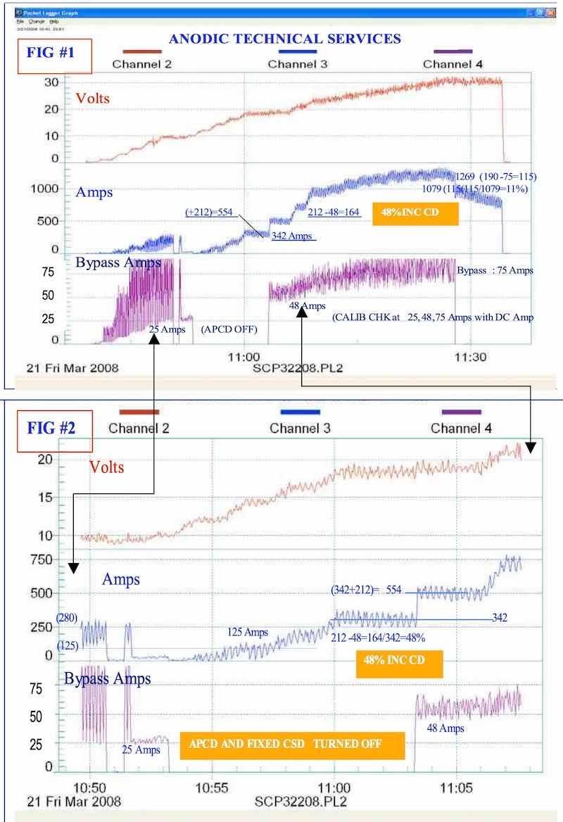 Figures 1 and 2
The process tank load was switched back to automatic ramp at 11:06 and continued to 1200 amps, with slow pulse at running constant current density, completing the run at 11:35. The fixed APCD or CSD bank was removed near the end of the run and indicated a net loss of 115 amps (or 11%) along with drastic amperage decay.
Three very important savings in time and efficiency must be reviewed and stressed here which are also directly related to total quality improvement.
- The 50-150 amps at 4-9 volts is strictly due to APCD. This represents 10% of the total process run, which simply would not be there without APCD.
- The 212 amps or 48% Net current increase at 19 volts due to APCD represents an unprecedented improvement. APCD and CSD increase anodize current by 100% at 10 volts and a minimum of 50% at 20 volts which is not only a conservative estimate, but also a remarkable savings.
- The standard slow pulse and fixed CSD show a minimum 11% increased current density at the end of the run which is still noteworthy due to significant time savings.
Specifications
The anodic pulse capacitance discharge (APCD) specifications depend upon slow pulse system operation as outlined / discussed in previous papers written in 2003 and 2006. The APCD pulse is being super imposed over the standard pulse system for 10-30 seconds, which actually results in a pulsed pulse system.
The overall APCD specific resistance bank specifications are difficult to list in detail because of the complex series parallel arrangement. Basic design specifications for successful 3000 amp units are as follows:
APCD: Pulsed 10-30 Seconds (from 0-20Volts Max.)
- 20 x 1.0 ohm Resistors per Bank
- 3 x 20 Resistors per Bank = 60 Resistors
- 0333 ohms Total Resistance
- 5-1.5 Henries Total Inductance
- 4200 Watts Maximum
APCD: Fixed CSD – No Pulse (0-75Volts or Max Output)
- 80 Resistors Series / Parallel
- 3-0.5 ohms Total Resistance
- 3000 Watts Maximum
A basic schematic drawing would show groups of 5 resistors in parallel, which are then connected in a series arrangement depending upon the rectifier output in the 500-1000-3000 amp range.
The rectifier should be Secondary SCR (Transformer Secondary Rectification and Control). Full wave and half wave rectifiers are acceptable from 30-100 volts output.
II. Electrolyte Chemistry
BackGround
Having been active in additives, modifiers and electrolyte chemistry since the first two patents in 1962 and 1968,4 there have been many breakthroughs. However, over the past year the reformulation and concentration of the chemistry has given much more surface activation in the ramp cycle than ever before. The addition of Amino Polycarboxylic Groups5 assist electrochemical surface activation along with specific hydroxyl donors which react together to reduce opposition forces (capacitance reactance) and field assisted dissolution at the anode. Over the past year, the additives and modifiers noted in the 2006 SURFIN paper have been concentrated into one accelerated modifier, which will assist the higher current densities to be more efficient at lower voltage and wattage. The new concentrated modifier (not additive) has become a much more active part of the electrolyte, replacing 20-25% of the total sulfuric acid and the destructive heat it produces. Now, anodizing all alloys in production with a lower sulfuric acid concentration is a reality. This was not previously possible. Yes, it is possible to process all alloys using only pulse technology. However, this new concentrated and activated electrolyte chemistry makes processing much easier. The 15%-20% acid concentrations called out in specifications like BAC 5821 are no longer necessary to process alloys like 2011, 2024, and 2219. All alloys process faster with greater anode efficiency. Higher concentrations of other MAE type additives can be used with fair success only when their concentration is increased to 10 - 15% and agitation is very high.
Application
A comparative analysis of additive concentration and activity can be made by measuring how effectively the additive carries out an oxidation reduction process at a low temperature (100-115°F). This is related to the energy and heat generation and absorption at the pore structure early in the ramp cycle. It is very important to achieve surface activation and absorb or remove excess energy and exothermic activity as quickly as possible when it is first generated on a nanoscale and molecular basis. The accelerated modified electrolyte does this with greater efficiency at a lower temperature.
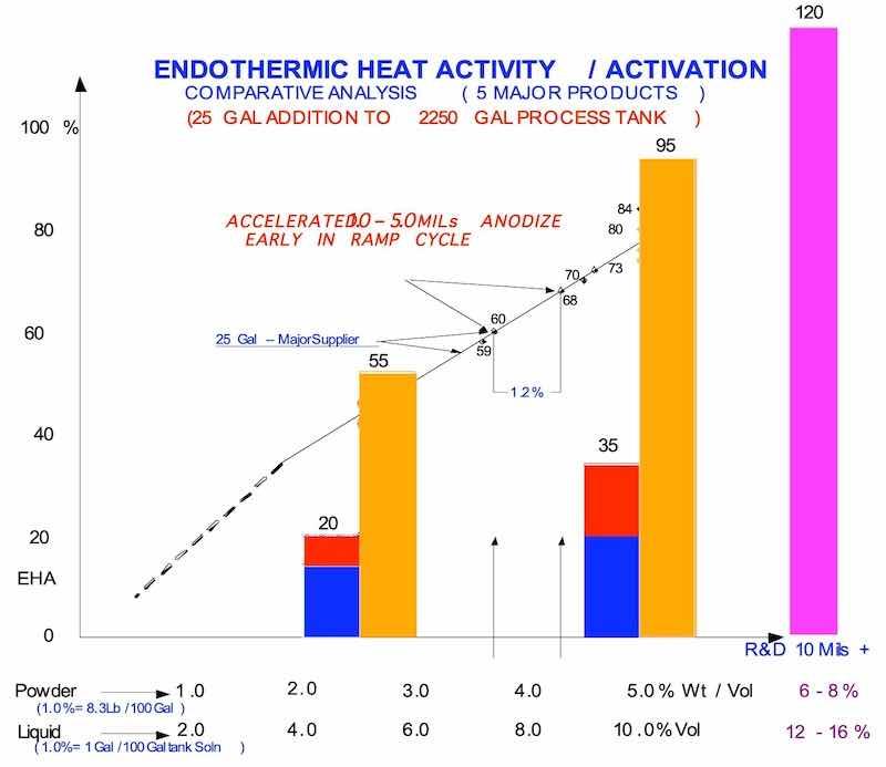 Figure 3
The differences in heat absorption can be seen in the graph (Fig. 3) which indicates percent endothermic heat activity and compares basic standard additives (Blue/Red-Max.) to concentrated Amino Polycarboxylic Modifiers and Activators (Gold), which are readily available and work more efficiently at lower concentrations than their counterparts. Tests were made at 5% and 10% by volume. Standard additives max out at 20 - 35% when used above their recommended concentration. The Amino Activated Modifiers have 55 – 95% comparative results when tested under identical conditions. This represents an increase in activity of 170 - 250% using standard parameters. The Bar Graph was prepared over numerous test results indicated on the linear graph in production.
III. Automatic Control
BackGround
As discussed in the previous papers, automatic control of the ramp cycle should always be a Slow Pulse - Step - Ramp in 2-4-10 second slow current Pulses. Slowly but surely, this Slow Pulse Technology6,7,8 is being realized and accepted by other Research Groups and Professional Anodizers.
The Automatic Control of Anodic Pulse Discharge during the ramp cycle - when it is most important - refers to the pulse switching of the APCD in parallel with the anodize tank load. The switching interval must be very slow – superimposed over the standard pulse – in order to allow for recovery time and anode capacitance discharge.
Application
By using ON/OFF anode switching times set at 10/15 second, and 15/30 second depending upon the alloy, the actual results have been quite dramatic; as one can see when comparing the graphs in Fig 4 and 5. Please pay attention to two important areas as we review these graphs:
- Total Amperage and Decay during ramp cycle
- Amperage Decay (ADO) during constant current density ranging.
For comparative analysis, the two real time data logger graphs were made running large production loads of flat panels at 15 ASF. Fig 4 shows a 9 Min. Ramp to 2700 Amps with Slow Pulse Step Ramp. There is no strong Amperage Decay (ADO) at the dwell step intervals.
A new tank load of the same panels was run with APCD and recorded as Fig 5. Please note the increased high current Pulse during the ramp cycle with a dramatic Amperage Decay (ADO) at 2400 Amps. The ADO can only indicate accelerated anodize build up which is totally due to APCD. In addition, the large ADO periods during constant current density ranging is a direct indication of a faster anodize coating rate, due to the fixed APCD to the end of the process cycle. This increased the coating rate by 25%-50% without any increase in voltage. The APCD operation here should be reviewed and stressed as related to increased current density, Amperage Decay (ADO) and pore structure development at lower current density.
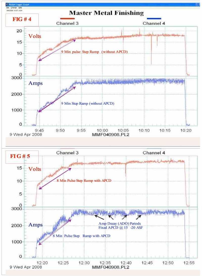 Figures 4 and 5
New Horizons
Recently, the need arose to set up a 3000 Amp anodize load at 15 ASF and try to anodize with the shortest possible time cycle for hard anodize type 23 at 80°F -85°F. The APCD was used with slow pulse and produced 0.4-0.5 mils in 18-20 min (at 18Volts) with a 7 min ramp cycle. The bright hard anodize finish dyed a deep jet black. The APCD makes it possible to achieve this on a repetitive basis and opens a whole new future for modern day high production anodizers.
IV. Summary and Conclusions
A summary of the intended techniques and the substantial improvements achieved with them can be as follows:
- Initiate Surface Activation and Anodizing immediately at the lowest possible voltage through the use of APCD.
- Remove the first excess exothermic energy as quickly as possible on a nanoscale or molecular basis through the use of the latest Advanced Activated Electrolyte Chemistry and APCD operating together.
Three particular companies working with these concepts have initiated surface activation and anodizing as low as 1-3 volts on 1500-3000 amp production loads immediately after positive buss bar contact has been made. The excess endothermic energy removal was initiated faster and much more efficiently (100% - 300%) using APCD and concentrated Amino Activated Modifiers.
Conclusions
- Anodic pulse Capacitance Discharge (APCD) will always improve the efficiency and increase current density at a lower voltage during the anodize ramp cycle on all type II-(23)-III anodize systems.
- APCD always increases current density on any slow pulse and/or fast pulse System.
- APCD promotes Amperage Decay (ADO) which is a direct indication of faster anodize buildup.
- APCD promotes ADO at current densities as low as 15ASF with Hard Anodic Coatings which also develops a better pore structure for dye penetration.
- Improvements in Amino Polycarboxylic Activated Electrolyte Modifiers along with (some) higher additive concentrations assist the higher current densities produced by APCD to be more efficient at lower voltage and higher wattage.
- Difficult Alloys like 2024, 2011 and 2219 run much easier with APCD due to lower voltage (Wattage) and electrolyte activation early in the ramp cycle creating cooler running conditions in the Nanostructure.
- Hard type II (23) and type III coatings processed with this technology are capable of meeting and exceeding the taber abrasion requirements of MILl-A-8625F due to anodize current early in the ramp cycle.
- Automatic ramping procedures for alloys like 2024-2011-2219-7075-7050 and 380 Die Cast can now be more simplified.
- Automatic ramping using APCD ensures maximum efficiency with increased repeatability of results, which fits right in with the continuous quality requirements of the present day NADCAP environment.
General References
- C. Schaedel, proc AESF Sur/Fin 2003; Anodize Additives and Pulse Ramp Systems
- C. Schaedel, proc AESF Sur/Fin 2005; Pulse Ramp Mixed Electrolyte Anodizing
- C. Schaedel, proc AESF Sur/Fin 2006; The Complete Spectrum Guide to Top Quality Anodizing
- C. Schaedel, U.S. Patent 3,418,222 (1968)
- C. Schaedel, proc AESF Sur/Fin 2007; Maximizing the Potential Future of Type II-III Anodizing
- Anne Deacon Juhl, “Theoretical Introduction to pulse Anodizing “, AAC, San Francisco, 2003.
- Anne Deacon Juhl, “Pulse Anodizing in an Existing Anodizing Line”, AluConsult, Denmark, 2007
- Anne Deacon Juhl, Kirsten Burfelt, and Peter Weldingh, “Slowing the Pulse” Products Finishing, p 34-37 March 2008.
Fred Charles Schaedel is President of Alpha Process Systems in Westminster, California. Visit http://www.alphaprocess.com. He started Anodizing and Plating at Hudson Plating Works and Harshaw Chem. Co. in Cleveland, Ohio, in 1957. He has developed specialized anodize additive modifiers, and pulse ramp systems — including waveform technology — and established training programs in the anodizing industry dating back to 1962.