Die castings pose some of the most challenging problems in anodizing.
The finish can be too thin, non- uniform and/or have an unfavorable appearance. These are common problems with a variety of practical solutions; they are easy to recognize, but in many instances, the source for the problem remains unknown. Critical to solving the problems of anodizing die castings is understanding the die cast substrate and the impact of surface condition, alloy composition, casting quality and microstructure on the anodizing process. Substrate quality issues are just as important, maybe more so, than anodizing conditions and technique.
 Dr. Mary Jude Runge and Larry ChesterfieldCertain optimum anodizing conditions may be used in some cases to help overcome less than advantageous metallurgical conditions. These include well known processing tools such as various pretreatment chemistries, higher anodizing bath concentration, and higher bath temperatures. These, and other recommended solutions are not successful in every case; sometimes trial and error testing on actual production parts must be done to find the best processing techniques. Through the use of actual case studies that provide real-life solutions in terms of anodizing theory and interfacial science, this paper provides some explanations by tying together metallurgical science with anodizing practice.
Introduction
Review of several questions received in Products Finishing Magazine1-8 determined generally consistent problems with anodizing die castings. The problems can be summarized as follows: 1) the anodic oxide finish is too thin to meet the necessary design specification or much thinner when compared to corresponding components manufactured from wrought processes; 2) the finish appearance is unfavorable: hazy, muddy, “not black enough”, and/or not uniform; and, 3) the corrosion resistance of the anodic oxide is insufficient. Review of recommended anodizing solutions to the various problems with anodizing cast alloys determined that they don’t always work, indicating that there are factors other than the anodizing process that impact the anodic oxide finish quality.
Consideration given to solve these rather easy-to-identify problems has illuminated four broad areas for discussion: 1) alloy selection, 2) substrate surface treatment, 3) anodizing process parameters, and 4) substrate quality. Of the four, perhaps the metallurgical factors that impact substrate quality: alloy composition, casting quality, microstructure and surface quality are dominant in determining anodizing conditions, technique and quality.
This paper will cover each of the four areas by discussing, in limited detail, the impact each has on the interface from which the anodic oxide originates and grows. Theoretical scientific reasons for why the problems occur and why most solutions succeed and some fail are followed by case studies that present actual problems and practical solutions based in the scientific background. The limitations as to what can be done from an anodizing standpoint to overcome the metallurgical condition of a cast substrate are presented not as an excuse, but as a call for understanding and communication between metal finishers, component designers who would like to use die castings, and the foundries who pour the castings in order to optimize product and process and to increase the use of anodized cast aluminum components.
Scientific Background
Aluminum Die Castings
Sand, Permanent and Semi Permanent Mold, Die Casting, and other related methods are all utilized today to provide cast aluminum product. The method of choice usually depends upon component size and design, lot size, and alloy requirements. Of these methods, die casting accounts for almost 70% of the total cast aluminum products available worldwide.
Aluminum die castings have been commercially available since the beginning of the 20th century. Castings are used for a variety of applications, from decorative sculptures and jewelry to automotive pistons and engine blocks.
Die casting is a versatile process for producing engineered metal parts by forcing molten metal under high pressure into reusable steel molds. These molds, called dies, can be designed to produce complex shapes with a high degree of accuracy and repeatability. Parts can be sharply defined, with smooth or textured surfaces, and are suitable for a wide variety of attractive and serviceable finishes.9
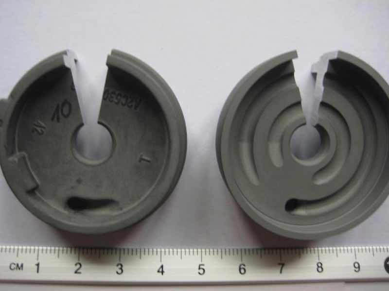
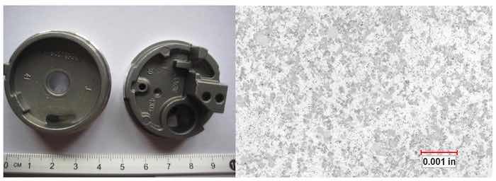 Figure 1: Examples of components die cast from alloy AlMg9 (similar to alloy 520), with corresponding microstructure (right). Multiple phases and intermetallic compounds are present throughout the microstructure as Mg2Si precipitates, hypoeutectic silicon and a fine network of Mg5Al8. When non- aluminum alloy constituents intersect the surface, they can interfere with the anodizing reaction.First and foremost, cast alloys are formulated for strength, hardness, and resistance to wear and fatigue. In aluminum casting operations, these properties are produced metallurgically two ways: (1) by solid solution hardening; that is: by the substitution of aluminum atoms with alloying atoms in the aluminum crystal structure and (2) by precipitation hardening: the dispersion of second phase constituents or elements in solution and precipitating them out as small intermetallic compounds, incoherent with the microstructure, which inhibit material deformation. Cast components have limited ductility and can be brittle; therefore, castings are not usually meant for subsequent deformation processing. Other than minimal finishing processes such as machining, a casting is typically produced to function near net shape.
Because cast components are produced to function near net shape, castings can be alloyed beyond what is typical for wrought products; that is, additions of other elements are at a higher per cent than the additions for alloys intended for extruded, rolled or deep drawn product (up to 16% total alloy content for castings vs. up to 8% for wrought alloys). As such, cast alloys are metallurgically more complex than their wrought counterparts; increased alloy additions produce correspondingly higher levels of solution phases, intermetallic compounds and precipitates. Castings, therefore, in addition to their strength and fatigue resistance, exhibit more complex surfaces, with less free aluminum, which make them more difficult to anodize. See Figure 1.
Cast Alloy Designations
The casting process and the alloy chemistry affect the level of microstructural homogeneity, the defect population and the variation of chemical potential across a cast component surface. It is important to understand the nature of the surface and therefore the interface between the component surface and the anodizing electrolyte such that anodizing process parameters can be modified to effect optimum oxide growth. This summary of cast alloy designations, compositions, and alloying elements is included for the understanding of three things: 1) how they affect the casting process, 2) how they affect the mechanical properties of the finished casting and 3) how they affect the surface, and therefore the anodizing process.
A system of four-digit numerical designations incorporating a decimal point is used to identify aluminum and aluminum alloys in the form of castings and foundry ingot. The first digit indicates the alloy group.10 Table I presents the US cast aluminum alloy designation system and the available product forms. Because die castings are primarily cast from the 300, 400 and 500 series designations, the following discussions will focus on these groups in particular.11 Table 2 presents the compositions of some commonly specified aluminum die cast alloys and their most similar European and Japanese designations.
300 Series: Silicon, with added Copper and/or Magnesium: The 300 series die castings are the most commonly produced and the highest-volume-usage alloys. Because they are comprised of multiple primary alloying elements, in addition to aluminum, the 300 series alloys exhibit the most complex microstructures and therefore present the most complex surface to the anodizing electrolyte.
300 series alloys contain, in addition to aluminum; silicon, magnesium and/or copper. In general, they fall into three types: Al-Si-Mg, Al-Si-Cu, or Al-Si-Cu-Mg. Silicon contents range from 5% to 22%. Copper contents range from 0% to a maximum of 4.5%. Magnesium content ranges from 0.3& – 0.6% for high strength alloys to 1.0% for the piston alloys 332 and 336. The addition of 1% - 3% Zinc in 300 series die castings (alloy 380) results in the highest strength cast aluminum based alloys commercially available.
Copper, as an alloy addition to aluminum castings, increases fluidity and decreases the surface tension of the molten pour and aids in producing a casting that is free of hot shortness and porosity. Within the microstructure, copper refines the grain size; that is, the presence of copper in the microstructure prevents excessive grain growth during cooling and heat treatment.
Both copper and magnesium increase strength and hardness in the as-cast condition through increased solid-solution hardening. Much greater increases are afforded by artificial aging (precipitation hardening). Precipitate structures are based on Mg2Si, and/or combinations of phases Al2Cu, Al2CuMg. In alloys that contain Zinc, Al-Zn-Mg phases form as well as Mg(Zn, Cu, Al)2. These phases are distributed throughout the cast microstructure, which means they also intersect the surface.
Copper, magnesium and/or zinc atoms reside on the aluminum lattice in alloy solution. This means that when present at the surface, copper atoms will inhibit the anodizing reaction. Precipitates such as Mg2Si are not coherent with the aluminum lattice, so while they do not anodize, they don’t confound the reaction. Instead, the anodizing reaction proceeds around incoherent intermetallic compounds, and they are taken into the anodic aluminum oxide (AAO) structure.
Higher silicon content 300 series alloys are preferred for casting by the die casting process. The thermal expansion coefficient decreases with increasing silicon, which prevents component shrinkage in the die as the component cools. A low expansion coefficient is beneficial for engine applications such as pistons and cylinder blocks, where tolerances are important. When the silicon content exceeds 12%, as in alloys 390 through 393, primary silicon crystals are present, and, if fine and well distributed, enhance wear resistance. Higher silicon content usually predicates large platelets of silicon in the microstructure. These also do not anodize, but are taken into the AAO structure as incoherent intermetallic compounds.
TABLE 1: Cast Aluminum Alloy Designation System and Available Cast Product Forms*
| Alloy Design. | Main Alloying Element(S) | Cast Product Forms Available |
| 200 | Copper | Ingot; Sand; and Permanent Mold Castings |
| 300 | Silicon; with added Copper and/or Magnesium | Ingot; Sand; Permanent Mold and Die Castings |
| 400 | Silicon | Ingot; Sand; Permanent Mold and Die Castings |
| 500 | Magnesium | Ingot; Sand; Permanent Mold and Die Castings |
| 700 | Zinc | Ingot; Sand; Permanent Mold and Few Die Castings |
| 800 | Tin | Ingot; Sand; and Permanent Mold Castings |
*Data taken from ASM Specialty Handbook, Aluminum and Aluminum Alloys, ASM International, Materials Park, OH, 199310.
400 Series: Silicon: These alloys are based on the binary aluminum-silicon phase diagram and contain from 5% to 12% Si. Alloys with these compositions find many applications where combinations of moderate strength, high ductility and impact resistance are required. The Al-Si system is a simple eutectic with limited terminal solubility and is the basis for the 400 series alloys. The limited solid solubility of silicon in aluminum produces Al-Si compositions that will exhibit approximately 1% Si in solid solution as a continuous phase, and the rest of the silicon will fall out as essentially pure particles that range in size from small particles to large needles and plates. See Figure 2.
Silicon is the alloying element that essentially makes the commercial viability of the high volume aluminum casting industry possible. Silicon content between 4% to the eutectic level of 12% reduces scrap losses, permits production of much more intricate designs with greater variations in section thickness and yield castings with higher surface and internal quality (forms sound outer surface layer), because of this, 400 series castings can be used in applications where pressure tightness is a requirement. These benefits derive from the effects of silicon and aluminum molten mixtures which exhibit increased fluidity, reduced cracking and improved feeding to minimize shrinkage porosity. Alloys with the eutectic composition (Al-12%Si) exhibit highest fluidity during casting.
Aluminum wear resistant alloys are based on the presence of the hard, brittle silicon phase. Alloying elements such as iron, manganese, and copper increase the volume faction of the intermetallic silicon- bearing phases, contributing to wear resistance. These phases are also distributed throughout the microstructure and impact the anodizing process when they intersect the component surface. Depending upon the population of such large plate-like or needle-like phases, AAO finishes that include Si particles exhibit lower cohesive and impact strength, the inability to absorb dye, and reduced corrosion resistance.
500 Series: Magnesium: The aluminum-magnesium alloys are essentially single phase binary alloys with moderate-to-high strength and toughness properties. Magnesium enhances the molten pour flow. Best corrosion resistance requires low impurity content in the initial pour, both solid and gas, which is difficult because aluminum is second to magnesium regarding affinity for oxygen. This requirement mandates that 500 series alloys be prepared from high quality metals and handled with great care in the foundry, giving rise to questions about effective recycling. Minor amounts of silicon are added to these alloys to precipitate Mg2Si intermetallic compounds for increased mechanical strength.
High corrosion resistance, especially to seawater and marine atmospheres, is the primary advantage of castings made of Al-Mg alloys. These alloys are also the most readily anodized and yield a favorable appearance after anodizing. The 500 series alloys are suitable for welded assemblies and are the best suited when an aluminum casting is needed for decorative or architectural applications. Aluminum- magnesium alloys also exhibit good machinability.
Table 2: Compositions of Some Commonly Specified Aluminum Die Cast Alloys*
| US Designation | European (E) and/or Japanese (J) Designation | Si | Fe | Cu | Mn | Mg | Cr | Ni | Zn | Sn | Ti | Other |
| 359 | AlSi9 (E) | 8.5 - 9.5 | 0.2 max | 0.2 max | 0.1 max | 0.5 - 0.7 | n/a | n/a | 0.1 max | n/a | 0.2 max | 0.15 |
| 360 | 9.0 - 10.0 | 2 | 0.6 | 0.35 | 0.7 | n/a | 0.5 | 0.5 | 0.15 | n/a | 0.25 | |
| A360 | AlSi10Mg(Fe) (E); ADC3 (J) | 9.0 - 10.0 | 1.3 | 0.6 | 0.35 | 0.4 - 0.6 | n/a | 0.5 | 0.5 | 0.15 | n/a | 0.25 |
| 380 | AlSi8Cu3 (E); ADC10Z (J) | 7.5 - 9.5 | 2 | 3.0 - 4.0 | 0.5 | 0.1 | n/a | 0.5 | 3 | 0.35 | n/a | 0.5 |
| A380 | AlSi9Cu3(Fe)(Zn) (E) | 7.5 - 9.5 | 1.3 | 3.0 - 4.0 | 0.5 | 0.1 | n/a | 0.5 | 3 | 0.35 | n/a | 0.5 |
| ADC10 (J) | 7.5 - 9.5 | 1.3 | 3.0 - 4.0 | 0.5 | 0.1 | n/a | 0.5 | 1 | 0.35 | n/a | 0.5 | |
| 383 | AlSi9Cu3(Fe) (E); ADC12Z (J) | 9.5 - 11.5 | 1.3 | 2.0 -3.0 | 0.5 | 0.1 | n/a | 0.3 | 3 | 0.15 | n/a | 0.5 |
| 390 | 16.0 - 18.0 | 1.3 | 4.0 - 5.0 | 0.1 | 0.45 - 0.65 | n/a | n/a | 0.1 | n/a | 0.2 | 0.2 | |
| B390 | ADC14 (J) | 16.0 - 18.0 | 1.3 | 4.0 - 5.0 | 0.5 | 0.45 - 0.65 | n/a | 0.1 | 1.5 | n/a | 0.2 | 0.2 |
| 413 | AlSi12(Fe) (E); ADC1 (J) | 11.0 - 13.0 | 2 | 1 | 0.35 | 0.1 | n/a | 0.5 | 0.5 | 0.15 | n/a | 0.25 |
| A413 | 11.0 - 13.0 | 1.3 | 1 | 0.35 | 0.1 | n/a | 0.5 | 0.5 | 0.15 | n/a | 0.25 | |
| C443 | 4.5 - 6.0 | 2 | 0.6 | 0.35 | 0.1 | n/a | 0.5 | 0.5 | 0.15 | n/a | 0.25 | |
| 516 | ADC6(J) | 0.3 - 1.5 | 0.35 - 1.0 | 0.3 | 0.15 - 0.40 | 2.5 - 4.5 | n/a | 0.25 - 0.40 | 0.2 | 0.1 | 0.10 - 0.20 | 0.1 |
| 520 | AlMg9 | 0.25 | 0.3 | 0.25 | 0.15 | 9.5 - 10.6 | n/a | n/a | 0.15 | n/a | n/a | 0.15 |
| 712 | 5.8Zn0.6Mg0.5Cr0.2Ti | 0.3 | 0.5 | 0.25 | 0.1 | 0.5 - 0.65 | 0.40 - 0.60 | n/a | 5.0 - 6.5 | n/a | 0.15 - 0.25 | 0.2 |
*Data taken from ASM Specialty Handbook, Aluminum and Aluminum Alloys, ASM International, Materials Park, OH, 199310.
Other Alloy Additions
Other alloying elements besides copper, silicon, magnesium and combinations thereof, are added to castings to produce second phase constituents that modify the aluminum-silicon structure and increase strength and hardness. A brief summary of common alloy additions and their role in the cast process and microstructure follows.
Iron: The solubility of iron in the solid state is very low in aluminum (~0.05%), therefore, most of the iron present in aluminum over this amount appears as an intermetallic second phase in combination with aluminum and other elements. Intermetallic compounds comprised of Aluminum-Silicon-Iron strengthen and increase the wear resistance of cast product. Because iron reacts with the aluminum and silicon to make a second phase, the structures tend to be finer than alloys with reduced iron content. Modified 300 series castings (A360 and A380) contain less iron, which increases their ductility and makes them easier to anodize.
Manganese: Manganese binds with Fe to stabilize the FeAl6 phase in heat treatable alloys, which modifies the microstructure by keeping the intermetallic phase from becoming needle-like or plate-like, which reduces die wear and makes the alloys easier to anodize. This microstructural modification increases ductility and toughness (impact strength), fluidity of the molten alloy during casting and decreases shrinkage with solidification.
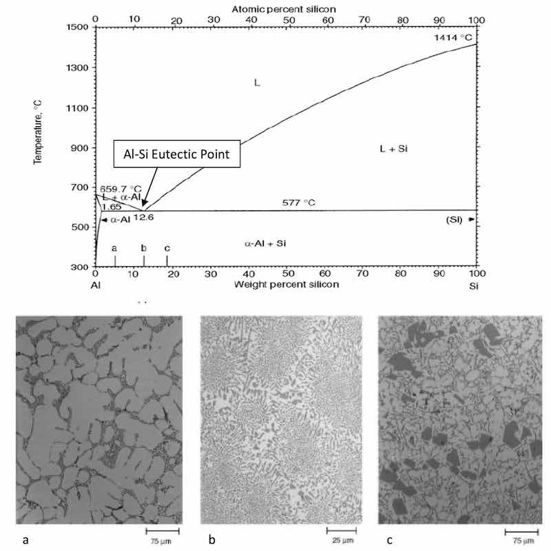 Figure 2: The Aluminum-Silicon binary phase diagram and associated microstructures at three Si compositions: a) Alloys with less than 12% Si are referred to as “hypoeutectic”, b) those with close to 12% are referred to as “eutectic” (the point at which a direct transformation from liquid to solid phase occurs), and c) those with greater than 12% Si are “hypereutectic”. Phase diagram and microstructures from Aluminum-Silicon Casting Alloys: Atlas of Microfractographs, Chapter 1, Introduction to Aluminum-Silicon Casting Alloys, ASM International, Materials Park, Ohio.13Zinc: Aluminum-zinc alloys were among the first to be commercially die cast at the beginning of the 20th century. The alloy ratios were zinc rich, and the castings were characterized by their tendency for hot cracking (cracking in the mold while cooling). Since this time, aluminum rich alloys that contain additional elements to zinc offer the highest combination of strength and fatigue resistance, based upon intermetallic compounds that form with magnesium, copper, chromium and manganese.
As a solid-solution strengthening addition, zinc resides on the aluminum lattice similar to copper and magnesium. According to Mondolfo, et.al, in alloys with less than 3% zinc, all zinc remains in solid solution.12Because of this, during anodizing, zinc can become entrained at the interface between the substrate and the anodic oxide, causing blisters and delamination of the AAO.
Chromium and Titanium: These are added in small amounts to inhibit nucleation of new grains as well as grain growth. Together with magnesium, chromium and titanium produce precipitates that enhance mechanical properties. Such additions can enhance the surface characteristics for anodizing.
Calcium, Sodium, Strontium and Antimony: These elements are added in small amounts to modify the aluminum-silicon microstructure when the silicon content is less than 12% (hypoeutectic). Alloys 360, 380, their modified versions (A and B), all 500 series alloys and some 400 series alloys are hypoeutectic; refer to Table 2 for die cast alloy chemistries. This modification produces a more fibrous and less needle- like Al-Si structure which is more fluid during casting and fine grained when it intersects the surface for anodizing.
Phosphorus: Phosphorus is added to modify the structure of hypereutectic (Si content is greater than 12%) Al-Si alloys. Alloy 383, 390, and alloy 413 are examples of hypereutectic compositions that could benefit from phosphorus modification. Modification helps to eliminate large, coarse primary silicon crystals that are harmful in the casting and machining of such compositions. The elimination of coarse primary silicon crystals also enhances the integrity of the AAO as larger silicon crystals, when included in the finish, reduce the cohesive strength of the finish and therefore its wear and impact resistance.
Controlling Cast Microstructure
Cast microstructure dictates the component quality. Because of the rapidity of the die casting process, microstructures are finer than components cast by other methods. The size and distribution of the various phases, compounds and precipitates hinge on: alloy chemistry, which includes the addition of elemental modifiers to the alloy chemistry; the casting method; the method and speed by which the casting is cooled, and whether it is heat treated (tempered) after it is finished.
To keep microstructures fine with complex alloys, the rate of cooling must be as fast as possible, in order to keep as much of the elements in solution. Precipitation and growth of intermetallic compounds, phase formation and grain coarsening will occur if the casting is slow cooled, or allowed to remain at a high enough temperature after ejection from the die. Tempering effects will be manifested in castings with large primary silicon crystals and coarse precipitates.
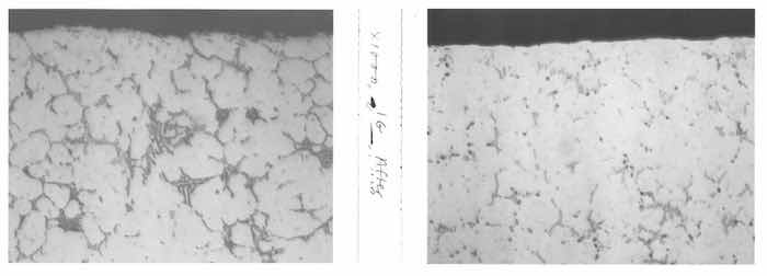 Figure 3: Die cast alloy ADC 6 (similar to alloy 516) microstructure before hot isostatic pressing (HIP) (left) and after HIP (right). Note how the needle-like Script phase, (Fe,Mn)3SiAl2, is re-dissolved in the Aluminum matrix. Mg2Si precipitates (small black-appearing dots throughout microstructure) are slightly coarser after HIP treatment.Die casting dies are designed with vents and cooling lines to facilitate rapid cooling. In addition, components can be ejected into a cooling tank to rapidly quench finished components. If cooling media is not turned over as rapidly as components are loaded, inadequate cooling can develop coarse cast microstructures.
Microstructures can be consolidated through post-heat treatment processes such as solution treatment, quench and temper, or through hot isostatic pressing (HIP). In the latter, the castings are placed in a container under pressure and heated close to the solution temperature. Phases are re-dissolved in the aluminum matrix, porosity consolidated, and in most cases, quality restored.14 See Figure 3.
Anodizing Complex Alloys
Anodic oxide formation is an electrochemical corrosion process that begins with nucleation at separate and distinct preferential sites across the substrate surface. Preferred sites are those which are not electrochemically complex, neither chemically (sites are comprised of aluminum only) nor topographically (surface is rather continuous with no burrs, laps or seams). In short, an ideal substrate is that which favors oxidation of aluminum.
![Figure 4: Schematic of the “network in the network” of the anodic oxide at the anodic oxide cell wall – electrolyte interface [16]. The structure of the anodic oxide is that of an ionic solid that facilitates ionic conduction. This conduction enables finish growth. Excess metal ions exist at interstitial sites of the network lattice. Interstitial Al3+ ions migrate together with electrons from the electrolyte during anodizing. Electrolyte reacts with these sites at the surface of the of the pore walls.](/images/images/runge/diecast/4.jpg) Figure 4: Schematic of the “network in the network” of the anodic oxide at the anodic oxide cell wall – electrolyte interface [16]. The structure of the anodic oxide is that of an ionic solid that facilitates ionic conduction. This conduction enables finish growth. Excess metal ions exist at interstitial sites of the network lattice. Interstitial Al3+ ions migrate together with electrons from the electrolyte during anodizing. Electrolyte reacts with these sites at the surface of the of the pore walls.In industry, an ideal substrate is rarely encountered. Products that are cast from aluminum alloys exhibit a variety of elemental additions that form alloy phases (which are homogeneous with the alloy system), intermetallic compounds (a compound of two metals that has a distinct chemical formula), precipitates (which fall out of alloy solution usually through heat treatment) and many other material defects that are on the microscopic and atomic level. Examples of atomic level defects are: grain boundaries, dislocations and vacancies, which are atomic level gaps and points of structural mismatch in the metallic crystal structure. The substrate electrochemical resistance changes with defects, alloy additions and contamination, especially when they intersect the surface, or interface between the substrate and the electrolyte. Therefore, all non-aluminum interfacial phenomena confound the anodizing reaction, retard it, and disrupt the anodic oxide structure.
Figure 4: Schematic of the “network in the network” of the anodic oxide at the anodic oxide cell wall – electrolyte interface [16]. The structure of the anodic oxide is that of an ionic solid that facilitates ionic conduction. This conduction enables finish growth. Excess metal ions exist at interstitial sites of the network lattice. Interstitial Al3+ ions migrate together with electrons from the electrolyte during anodizing. Electrolyte reacts with these sites at the surface of the of the pore walls.In industry, an ideal substrate is rarely encountered. Products that are cast from aluminum alloys exhibit a variety of elemental additions that form alloy phases (which are homogeneous with the alloy system), intermetallic compounds (a compound of two metals that has a distinct chemical formula), precipitates (which fall out of alloy solution usually through heat treatment) and many other material defects that are on the microscopic and atomic level. Examples of atomic level defects are: grain boundaries, dislocations and vacancies, which are atomic level gaps and points of structural mismatch in the metallic crystal structure. The substrate electrochemical resistance changes with defects, alloy additions and contamination, especially when they intersect the surface, or interface between the substrate and the electrolyte. Therefore, all non-aluminum interfacial phenomena confound the anodizing reaction, retard it, and disrupt the anodic oxide structure.
Critical to understanding the side reactions that occur during anodizing is the recognition that the anodic oxide is an ionic solid comprised only of hydrated aluminum oxide. The structure exhibits minimal x-ray diffraction contrast, and is therefore designated amorphous but has been shown to exhibit short range order15, which gives it an almost crystalline character. The anodic oxide structure is comprised only of aluminum and oxygen ions coordinated as AlO4 - tetrahedra which form the “network in the network” of self assembled, highly ordered nanoscale columns16. See figures 4 and 5.
![Figure 5: Representation of anodic oxide structure comprised of AlO4 tetrahedra with short range order reported by Brodalla [15]. These tetrahedra comprise the internal network of the individual cells which make up the nanoscale network of the anodic oxide.](/images/images/runge/diecast/5.jpg) Figure 5: Representation of anodic oxide structure comprised of AlO4 tetrahedra with short range order reported by Brodalla [15]. These tetrahedra comprise the internal network of the individual cells which make up the nanoscale network of the anodic oxide.The aluminum substrate lattice is face centered cubic (fcc), which presents a structural mismatch between the substrate and the forming anodic oxide’s body-centered tetrahedral structure (bct). An aluminum alloy substrate lattice contains non-aluminum atoms in substitutional solution as well as interstitial intermetallic compounds that are not coherent with the microstructure. Since the anodic oxide will not comprise these non-aluminum atoms or intermetallic compounds, a compositional mismatch is also present between the substrate and the anodic oxide.
Figure 5: Representation of anodic oxide structure comprised of AlO4 tetrahedra with short range order reported by Brodalla [15]. These tetrahedra comprise the internal network of the individual cells which make up the nanoscale network of the anodic oxide.The aluminum substrate lattice is face centered cubic (fcc), which presents a structural mismatch between the substrate and the forming anodic oxide’s body-centered tetrahedral structure (bct). An aluminum alloy substrate lattice contains non-aluminum atoms in substitutional solution as well as interstitial intermetallic compounds that are not coherent with the microstructure. Since the anodic oxide will not comprise these non-aluminum atoms or intermetallic compounds, a compositional mismatch is also present between the substrate and the anodic oxide.
Another thermodynamic mismatch is present because there are diffusion rate differences between metals and oxides (diffusion occurs faster in metals). Since the substrate is the source for the anodic oxide constituents, and the anodic oxide is the result of the continued reaction of the electrolyte with the substrate surface, the interface of the electrolyte and the surface is the key to continued anodic oxide formation and growth.
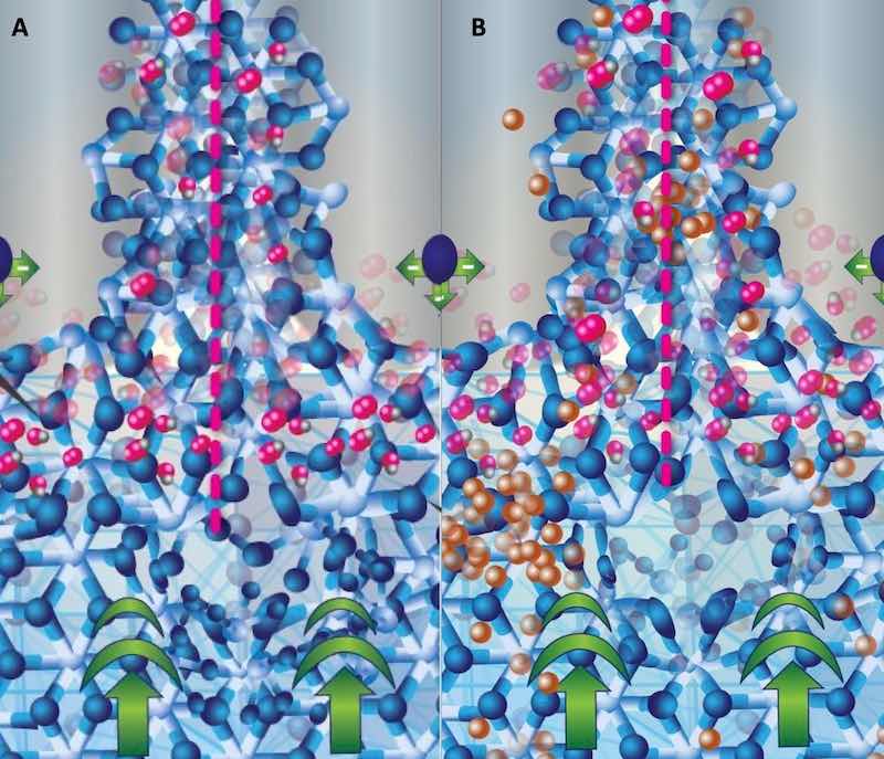 Figure 6: Schematic of the walls of the anodic oxide at the junction of three anodic oxide cells. An entire cell is bracketed with pink dotted lines; the central pore appears gray with repulsive forces represented by a single sphere. The fcc aluminum structure is at the bottom of the schematic with the current bias represented by bold green arrows. The forming bct structure (A and B) exhibits the primary oxidation reaction at the interface between the fcc and the electrolyte in the pore by the presence of oxygen atoms on the bct structure. The schematic on the right B shows non-aluminum ions (copper colored) diffusing from the fcc lattice, through the bct anodic oxide network, into the central pore where it will be carried into the electrolyte. Note how the copper atoms “pile up” at the fcc-bct interface. This is due to the structural/compositional mismatch between the aluminum and the anodic oxide.In nature, energy is required to overcome a mismatch. Energy produces heat. Non-aluminum metallic ions (copper, zinc, and other metal ions in solution with the aluminum alloy substrate) tend to “pile up” at the interface and must realign themselves as they move from their positions on the substrate lattice to interstitial spaces within the anodic oxide lattice. Once they find a space, they move slower as they “hop” through the spaces in the anodic oxide network while aluminum ion diffusion occurs on the bct lattice which comprises the forming anodic oxide cell. The kinetics of the primary oxidation reaction are therefore retarded when anodizing complex alloys that are rich in non-aluminum elements in solid solution (such as die castings, and 2000 series and 7000 series wrought alloys). An increased resistance heating results at the interface; producing thin, rough finishes that often exhibit deposits of sooty-appearing reaction byproducts. See Figure 6.
Inclusions, intermetallic compounds, precipitates, and other insoluble alloying elements that are incoherent with substrate microstructure are not anodized; instead, the primary oxidation reaction proceeds around them, taking them up into the anodic oxide. The impact of inert or insoluble defects such as inclusions and microconstituents that are not soluble in the aluminum matrix (e.g. lead and hypereutectic silicon) on the finish is in the spacing of the initial corrosion nuclei that precede the anodic oxide network and in the coherency of the AAO structure. This disruption in order can lead to irregular growth and irregular inter-column spacing. However, as the surface is consumed and a more ordered surface is presented for oxidation, the oxide growth recovers, but the surface of the oxide often replicates the defect, making the surface rougher. Mass transport of inclusions and insoluble species also occur through the network; although they are never incorporated into the structure itself. Side reactions such as these also retard the kinetics of the primary aluminum oxidation reaction.17 However, depending on the amount and distribution of incoherent defects, less energy (heat of reaction) is required at the interface to overcome such defects than the energy required to overcome the effects of substitutional elements in solution with the substrate on the anodic oxide formation and growth. See figure 7.
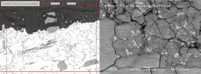 Figure 7: Metallographic cross section of die cast alloy AlSi9Cu3Fe (similar to alloy 383). In the micrograph on the left, large hypereutectic primary silicon platelets from the microstructure as well as smaller eutectic needles are incorporated into the anodic oxide. In the Scanning Electron Microscope (SEM) photomicrograph on the right, the surface of the component is documented, showing the cracks dotted with white-appearing silicon as well as copper deposits appearing as darker-gray haze across the surface and concentrated in areas near the cracks.Complex alloys, such as die castings, offer mixtures of inclusions, phases and intermetallic compounds which confound the anodizing reaction. With as many various defects as the die casting contains, various side reactions occur to impede the surface reaction. The realignment of the non-aluminum substrate elements in solution and mass transport of inclusions and insoluble alloy additions such as hypereutectic silicon compete with the oxidation kinetics, resulting in repeated restructuring of the substrate surface which in turn disrupts the order of the anodic oxide. Depending upon the size and population of insoluble defects, the cohesive strength of the finish can be reduced and paths for environmental ingress can be created, reducing the corrosion resistance of the finish; furthermore, the continuity of the porous structure will be interrupted, causing a marked decrease in dye uptake. See Figure 8.
Practical Applications
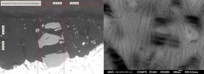 Figure 8: (Left) Higher magnification photomicrograph of the metallographic cross section of die cast alloy AlSi9Cu3Fe (similar to alloy 383). Hypereutectic silicon platelets account for most of the finish thickness which ranges from 15μ to 32μ. Note the crack to the left of the red lines that bracket the large Si platelets extends the entire finish thickness. Field Emission SEM image of an anodic oxide on the same alloy, note the typically ordered columnar structure is skewed by inclusions from the base material. Inclusions, primary silicon phases, and any non-aluminum intermetallic compound will disrupt the order of the anodic oxide and produce finish defects.The following case studies discuss actual questions posed in Products Finishing Magazine and actual problems encountered in production anodizing. The questions are presented as written, but the answers are more detailed and comprehensive than initially printed. These answers reflect the added space that a technical paper provides; the answers initially presented are nevertheless the authors’ best efforts, and to the best of their knowledge and expertise.
Case Study Number 1: Anodizing Die Cast Aluminum Alloys – Alloy Selection
What is the best die cast aluminum alloy to use (such as A360, A380, A356, etc) to get the best anodizing results in terms of both the anodizing quality and ease of production?
Alloy 356 can be cast both as a sand casting and as a permanent mold casting. A356 is used in permanent mold casting. Alloys 360, A360, 380 and A380 are used in die casting. For this group of alloys, generally speaking, the tensile strength increases from sand, permanent mold to die cast. All of the alloys mentioned, A356, A360 and A380, will anodize. Of the three casting alloys mentioned in the question, A356 would be easiest to anodize because it is lowest in silicon and has only a small amount of copper. The “A” designation before these alloys indicates that the iron content has been lowered and this helps a great deal with their response to the anodizing process. The 360 and A360 are nearly 50% higher in silicon than 356 / A356. Even the A360 contains more iron than the 356. Alloys 380 and A380 contain the same silicon and iron, respectively, as 360 and A360, but the 380 series is much higher in copper than both, the 356 / A356 and the 360 / A360 and contains 3% zinc. So, in the order of least desirable to most desirable to anodize, it would be 380, A380, 360, A360, 356, A356. Alloy 360 will anodize easier than alloy 380 because, even though it has higher silicon, it has almost no copper.
Whichever alloy is anodized the quality of the die casting is critical to achieving a good anodized finish. Grain size, intermetallic formation and phase distribution are the important factors affecting casting surface soundness and uniformity. In high silicon alloys, such as 360 and 380, the silicon phase is hard, and depending upon composition and cooling rate, particles can be fairly large and plate-like in appearance. Since silicon does not anodize, it is included in the anodic oxide and can result in irregular finish thickness, excessive finish roughness and reduced finish cohesive strength (Taber values will be unacceptable). Neither copper nor zinc anodizes, but since they are in solution with the aluminum, their presence causes interfacial resistance and therefore heat between the substrate and the anodic oxide, causing a finish with an irregular, blotchy surface appearance after anodizing. Zinc can become trapped at the interface and oxidize, causing blisters at the interface. To minimize these effects, it is necessary that copper and zinc containing phases be small and homogeneous throughout the cast microstructure.
The shape and distribution of hypoeutectic silicon (both alloy 360 and 380 contain less than 12% Si) can be controlled by the addition of sodium or strontium. This is done in the melt stage of the casting. Modification encourages the formation of a finer Al-Si eutectic network in the cast microstructure. Grain size and precipitate size are also kept to a minimum with rapid cooling rates and by the addition of iron to the alloy. Therefore, although reducing iron as in “A” modifications of 300 series alloys will enhance surface finishing, a decrease in iron will produce coarser silicon crystals in the casting microstructure. By adding sodium or strontium to modify the alloy chemistry, the silicon will be refined, producing castings which have the fine grained microstructure desired for better mechanical properties with lower iron which yields a surface that is easier to anodize.
Cleaning the parts should be accomplished with a mild, non-etching alkaline cleaner and a deoxidizer / desmutter containing some fluoride. Fluoride will help to dissolve the silicon that is at the surface of the die cast microstructure. There is always silicon at the surface of 300 series and 400 series cast alloys. Desmutting should also help remove residual copper and zinc from the component surface. Anodizing should be done in a bath of 200 to 250 g/l sulfuric acid at 70 degrees F. Lower anodizing current densities that allow resulting voltage to remain with the 13 to 16 volt range may help in producing a more uniform finish.
Although not a die casting alloy, alloy 535 (formerly known as Almag 535) is probably the best casting alloy to anodize. It is low in silicon, iron and copper and high in magnesium. Alloys 516, 518 and 520 are examples of die casting alloys from the 500 series that anodize well. Selecting this alloy for components enables the cast surface to form a high quality anodic coating that takes color well whether coloring by dying, integral coloring or electrolytic coloring.
Please also be aware that the nature and quality of the casting itself has a lot to do with the response to anodizing. Generally speaking, in order of best to worst response to the anodizing process, it would be permanent mold casting (best), followed by sand casting and die casting. But, if the quality of the casting is poor, any of these casting methods may yield a poor response to the anodizing process.
Case Study Number 2: Hard Anodizing Die Cast Alloy 360 vs. Wrought Alloy 6061 – Alloy Selection
A 6061 alloy component which has been routinely hard anodized (Type III) to a coating thickness of .001” to .0015” was recently switched from to a die casting alloy 360 but still requires the same coating thickness. Attempts to process these parts in accordance with MIL-A-8625, Type III have resulted in a .0004” coating. Is it possible to build a coating of .001” to .0015” on alloy 360?
In this case, the customer switched from one of the best hard anodizing wrought alloys to a die casting alloy. The 300 series die cast alloys can be tough to anodize because of the very high silicon content, about 9.5% in the case of 360. The problem with these alloys is that the alloying elements don’t anodize. A cost savings in machining may have been achieved but the ability to get the desired coating thickness may have been jeopardized.
Thicker coatings may be achieved on 360 and 380 by first processing with a light acid etch containing fluoride, e.g., 30 seconds in a 10% to 15% ammonium bifluoride bath at 130°F. This removes much of the surface silicon. Anodize in 15% sulfuric with organic additives at 70°F and 24 amps per square foot for up to 60 minutes to achieve a coating thickness of greater than .0004”. The final result will still be affected by alloy chemistry and casting quality.
Case Study Number 3: Anodizing Highly Alloyed Die Cast – Alloy Selection and Surface Treatment
Components that are made of alloy ADC12 (equivalent to EN46100) should be anodized with a Type II finish. Briefly, the process is: shot blast, rinse, rinse, “DI” rinse, anodize 10-11 volts D.C. for 20 minutes at 200 g/l sulfuric acid and temperature of 14°C to 18°C (57°F to 64°F), rinse, rinse, “DI” rinse, “DI” rinse, room temperature nickel fluoride seal for 15 minutes, rinse, air dry.
The anodized parts are a dark gray color. In addition, the parts show corrosion pitting over more than 10% of the test panel after only 72 hours salt spray testing. Is this normal?
Alloy ADC12 is high in silicon (9.5% to 12%) and copper (1.5 to 3.5) and zinc (1%). It is most like Aluminum Association alloy A384. Most die cast alloys are high in silicon with the exception of the Aluminum Association designated 200 and 500 series alloys. Silicon is not soluble in the aluminum matrix and does not anodize. So with high silicon alloys (usually above 7% or 8% silicon) the anodizing can result in a brownish, gray, or black. Copper and zinc, because they are soluble in the matrix, and also do not anodize, retard the anodizing reaction, and can cause discoloration and burning of the finish, and will always produce a thinner finish under normal anodizing conditions, sometimes yielding a “sooty” appearance. This depends on both the chemistry of the alloy and the quality of the die casting. In some cases the anodic coating may not be dense or continuous and, thus, the reason for not passing the salt spray test.
Finish thickness and uniformity are not addressed in the question. Although the presence of second phases and silicon crystals at the cast surface can hinder anodizing, an irregular surface due to shot blasting will also confound the anodizing reaction by creating a non-uniform charge distribution across the surface of a component. Because the uniformity of a shot blast surface is random, components in a process single lot, anodized on the same rack, may vary in finish quality and thickness. This condition will clearly result in variations in corrosion test performance.
Added silicon and other alloying elements enhance the casting characteristics of the alloy and impart strength to the finished casting. Unfortunately, they can be a detriment to anodizing. If it is possible to use alloys that contain little-to-no copper or zinc, and to use an alloy that is as low as possible in silicon – certainly less than 7%, do so. A modified, low iron, version of the alloy is being used (typically iron is reduced to increase the ductility of the casting); however, if the alloy were further modified by a strontium or sodium modification, the silicon phase would be refined, yielding a component that should be easier to anodize.
The concept of modification from a metal finishing point of view is well addressed by Alan DeRoss18 in “Aluminum Castings for Finishing,” Plating and Surface Finishing, February, 1977, pp 38 – 40:
“Aluminum-silicon alloys have a special problem. Since a negligible amount of silicon is soluble in aluminum, the silicon forms a mixture with aluminum called the aluminum-silicon eutectic. In this mixture the silicon crystals are coarse, hard, plate-like particles and can grow relatively large. Also, large particles promote uneven distribution of the eutectic phase. The result of all of this can be unsound metal and a blotchy, sooty appearance after anodizing. The crystal size and distribution of the silicon can be controlled by the addition of such elements as sodium and strontium. The result of such additions is to convert the eutectic mixture containing coarse silicon flakes into a finely dispersed mixture. This treatment is called “modification”. The finely divided and dispersed silicon promotes better “feeding” of the alloy and a sounder metal structure is obtained. The appearance and quality of subsequent surface finishes are greatly enhanced by “modifying” aluminum-silicon alloys. This treatment is accomplished during the melting operation.”
The quality of the anodizing will be determined primarily by the amount of silicon and other alloying elements in the alloy, what, if any, “modification” has been done and the quality of the casting. There is nothing wrong with the anodizing process. Low voltage is good, but results might improve if you use a higher anodizing bath temperature. Try using 22°C to 24°C (72°F to 75°F). Check into the possibility of anodizing components that are not shot blasted; the results might be astonishingly different.
Case Study Number 4: Hard Anodizing 500 Series Alloys - Surface Treatment Effects19
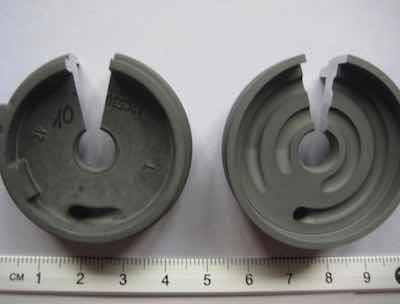 Figure 9: Documentary photograph of die cast components which exhibited non-uniform finish thickness. Sections were taken from each part for metallographic examination.The client reported that die cast components exhibited finish thickness variations after anodizing, even on components finished on the same rack. The variation did not correspond to component location on the racks or to how the parts were contacted on the racks. Furthermore, thickness variation was also measured across the surface of individual parts, with the machined surfaces exhibiting a uniform and continuous finish thickness. The areas that weren’t machined (darker appearing surface as-received) on the parts exhibited discontinuous and unacceptably thin anodic oxide finishes. It was requested that the components be analyzed to determine the nature and cause of the problems. See Figure 9.
The components were die cast aluminum alloy AlMg9 (similar to alloy 520) which contains: 2.5% Si (max), 1.0% Fe (max), 0.1% Cu (max), 0.55% Mn (max), 8.0 – 10.5% Mg, 0.1% Ni (max), 0.25% Zn (max), 0.1% Sn (max), 0.2% Ti (max), and 0.1% Pb (max). Because the alloy is low silicon and low copper, the resultant cast microstructure should not be difficult to anodize.
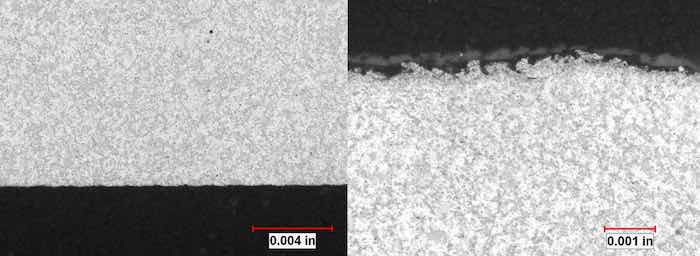 Figure nos.10 (left) and 11 (right): Documentary photograph of the machined surface of the die cast component before anodizing. The charge across the surface would be uniform during anodizing. The surface on the right is typical of a shot blasted surface. Note the non-uniformity of the surface. The charge distribution would be exceedingly non uniform, creating a situation where the finish growth would not be uniform.Anodizing process scrutiny disclosed no deficiencies which would have caused the variations in finish thickness. Detailed analysis of components in the as-received and as-finished condition proceeded to determine the nature and cause for the problem.
SEM analysis disclosed the surface of the components that was not machined had been bead or shot blasted; producing a rough surface with many burrs and laps. EDS analysis determined that there were no gross surface chemistry differences that would have lead to the observed differences in the anodizing reaction. Comparing the same areas in unfinished and finished condition metallographically revealed the irregular surface features created through bead/shot blasting as the source for the non-uniformities measured and observed on the die cast components. See Figures 10 to 13.
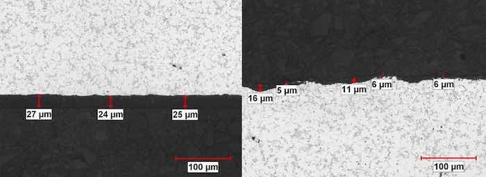 Figure nos. 12 (left) and 13 (right): Machined surface of pump component as-anodized (left). Note the anodic oxide (designated with red arrows) is uniform and continuous and measures an average 25 microns thick. Shot blasted surface after anodizing (right). The areas with the burrs exhibited exceptionally thin anodic oxide finish (5 – 6 microns). To contrast, note the area where the finish measures 16 microns exhibits no burrs. The anodic oxide finish with corresponding thickness values is indicated with red arrows.Burrs, laps and the seams that they cause between the machined defect and the substrate are well documented sites of localized anodic charge concentration which prohibit uniform anodic oxide growth. These are points of resistance heating, hyper-growth and ultimately thin discontinuous anodic oxide finishes because, when the process current bias is imposed, the burrs stand immediately upright as the charged defects repel the surface (similar charged objects repel one another). The burrs proceed to anodize through, breaking off into the electrolyte, leaving bare areas of substrate that begin to anodize later in the cycle. Because the blasted surface condition was not uniform from component to component, the resultant finish thickness could not be uniform. This produced the measured non-uniformities which were the cause of the investigation.
Case Study Number 5: Anodizing Die Cast Aluminum Alloys – Surface treatment
There is interest in finding some information about anodizing an aluminum die cast part. The two alloys being considered are 360°F and 380°F. Are there any aluminum die cast alloys that would take an anodized finish better than others? The parts will be polished before the finishing operation. The parts are produced in China.
Both 360 and 380 die cast alloys can be successfully anodized. The 360 alloy is high in silicon (9 – 10%) and low in copper (0.6%) while 380 is fairly high in both of these alloying elements (7.5 – 9.5% Si and 3 – 4% Cu). 380 alloy also contains 3% zinc. The “F” version indicates the components are in the as-cast condition, no additional heat treatment is performed on these castings. The “A” version of both alloys is lower in iron which helps produce a better anodized finish. Because alloy 360 is much lower in copper, it will yield thicker, more uniform finishes with less black residue or “smut”.
Polishing of the castings may result in the “high” points of the metal surface being smoothed over resulting in “voids” in the metal that may be revealed in the anodizing process. Since the silicon phase is harder than the matrix aluminum, more silicon will be exposed, and predicate the need for a bifluoride treatment prior to anodizing. Experimentation with polishing processes and techniques is necessary to see if the finish appearance is enhanced.
Case Study Number 6: Anodizing and Dyeing Die Cast Alloy 383 – Anodizing Parameters and Substrate Quality
There is a request to anodize and dye black some sample pieces of 383 alloy. The parts as-anodized exhibited a “hazy” finish with a brownish appearance. The parts would not dye well at all. In fact, there was no apparent change in the color after dying. Type II anodizing was performed at a bath temperature of 20°C-22°C (68°F-72°F). The dye is an inorganic black dye called “Sodium Sulfahydrate, Solid Ordinal Colorant (Amoniac)”. The dye does not appear to be the problem since the parts did not look good after anodizing. What can be done to get an acceptable black color?
Similarly, there is a request to anodize a 383 alloy die cast part and color it blue. The shade of blue is not important as long as it is uniform in appearance. Is there such a process; how will the uniformity of color be; how would the part best be processed?
Situations with different alloys and products require experimentation by anodizing some pieces to see what results can be obtained. Nothing speaks louder than actual results.
Alloy 383 is a high silicon, high copper, high zinc die casting alloy that is difficult to anodize under any conditions. Cleaning the parts should be accomplished with a mild, non-etching alkaline cleaner and a deoxidizer / desmutter containing some fluoride. Fluoride will help to dissolve the silicon that is at the surface of the die cast microstructure. There is always silicon at the surface of 300 series and 400 series cast alloys. Desmutting should also help remove residual copper and zinc from the component surface. Both treatments should help minimize the brownish gray or gray with mottled brown areas that are common after anodizing both 380 and 383 alloys.
A 20% to 22%, by weight, sulfuric acid anodizing bath would work best as it requires lower voltage for a given current density than lower concentration baths. Try anodizing at a current density with a potential response of 12 or 13 volts, or lower, at a bath temperature of 24°C-26°C (75°F-78°F) for 20 to 30 minutes. Rinse in a dilute nitric acid solution to remove excess copper and zinc from the surface of the anodic oxide and re-rinse with DI water before proceeding to the dye tank. Dye the anodized parts and observe the overall appearance to see if it is acceptable.
Look closely at metallurgical quality of the casting by metallographically preparing a cross section of the die cast component. The casting should have a uniform and continuous surface, free of voids or interconnected porosity. There will always be silicon in the microstructure and other inclusions, but they should be small and not agglomerated. Segregation in the cast microstructure can be reflected and replicated in the anodic oxide finish.
Case Study Number 7: Anodizing and Dying of Aluminum Die Castings – Anodizing Parameters and Substrate Quality
There is a problem during black anodizing on an aluminum die cast alloy ADC12 whereby the black color is not dark enough. Here are several questions about this process:
- Is the main purpose of desmutting to take away the silicate?
- What is the standard thickness that we should expect for black anodize on ADC12?
- What is the best way to measure the coating thickness on this part?
- Will the thickness tester reading be the same as what we would read on an aluminum extrusion with the same coating thickness as the die casting?
The subject alloy is high in silicon (9.5% to 12%) and copper (1.5 to 3.5) and zinc (1%). It is most like modified die cast alloy A384. Die cast alloys such as this one are high in silicon because the silicon makes the metal flow into the mold much easier and the components have a lot of mechanical integrity. Unfortunately silicon is not soluble in aluminum. As such, it does not homogenize with the aluminum. Silicon does not anodize. So the free silicon in these alloys often gives a brownish, grayish, or black appearance when anodized. Copper and zinc, because they are soluble in the matrix, and also do not anodize, retard the anodizing reaction, and can cause discoloration and burning of the finish, and will always produce a thinner finish under normal anodizing conditions. This also makes it difficult to get enough anodic coating thickness to absorb the organic dye. With a relatively thin coating not as much dye can be absorbed so the color may not be as dark as desired. One cannot say exactly what coating thickness to expect on this alloy; it depends on the actual substrate quality as well as the processing (anodizing) conditions. Even 6 – 8 microns finish thickness may not be enough to give a good black color.
It is necessary to calibrate the thickness tester on the type of part subject to measurement at the time of measurement. If an eddy current coating thickness tester is calibrated on an extrusion it will not measure correctly on the die cast alloy. The calibration of the instrument should be done on an uncoated part of the same alloy and type (casting, wrought or powder metal) that is going to be measured. The accuracy of the measurement may depend somewhat on the quality of the casting. Die castings that are more porous, or which have been shot blasted, may not measure well, or consistently.
The purpose of desmutting after alkaline etching is to remove the alloying elements on the aluminum surface. These aren’t removed in an alkaline formulation. Only the aluminum is etched in the alkaline etching bath. The alloying elements are “released” and remain on the surface of the parts until they are removed by a strong acid desmutting solution. If alkaline etching of any casting that is to be anodized can be avoided, the overall appearance of the finished part will most likely be enhanced. A typical cleanup sequence might be: alkaline or acid based detergent, rinse, desmut/deoxidize, rinse, anodize. Silicon will still be present at the surface of the component after this process, and depending upon size and distribution, may or may not yield and uniform and continuous finish with the clarity necessary for a good black finish.
Case Study Number 8: Anodizing High Silicon Alloy Die Cast Parts – Substrate Quality
The client is anodizing a cast aluminum part for a medical device. The specification is alloy A360 with MIL-A- 8625 Type II sulfuric acid anodize, clear finish. The parts are die cast, machined, light steel bead blasted, and then anodized. The finishing process is caustic dip pre-treat, nitric acid desmut, anodize, and nickel acetate seal. After anodizing, the components exhibit a black residue that wipes off and, later, there is also a white precipitate that occurs when the part is exposed to a saline solution that runs through it. Stripping and re-anodizing have been attempted, but the smut is worse after reprocessing. The smut seems variable, that is, some parts are better than others.
Useful background information: The aluminum is confirmed as A360 thru metallurgical analysis of the raw material. Through scanning electron microscopy it was determined the surface elements of the part include Al, Si, O, and S. The particles are approx 50 to 75 microns in size, and confirmed to be the same elemental composition. It is believed the anodizing is correct because I don't detect any of the other alloy components except for perhaps the silicon that is not dissolved during the pre-treatment.
Questions:
- Are there any other process considerations that need to be taken into account for the preparation and anodizing to reduce the smutting?
- Knowing this is a high silicon alloy is this problem even "fixable", or should the customer consider finding a new material?
It is important to remark that the “metallurgical” analysis that was performed that confirmed the cast component as A360 was most likely a “chemical” analysis – the composition was confirmed but no microstructural information was determined. Metallurgical analysis would require a cross section of the component be prepared for metallographic examination, enabling evaluation of the cast microstructure at the surface, which determines if substrate quality is a factor in the problems encountered during surface finishing.
Based upon the details of the SEM examination, it sounds like the anodic oxide is actually flaking off of the component surface (the elemental composition of particles removed from the component corresponds to the elemental composition of the anodized finish). This means adhesion of the finish to the substrate or to itself is an issue. Whether flaking occurs directly after anodizing or after the saline solution has run through the component is unclear by the description. Finish delamination from the substrate almost always indicates a substrate quality problem. Finish flaking from itself indicates a different type of corrosion problem. If the failures occur through application, perhaps there is turbulent flow in the component, and cavitation or erosion of the anodic oxide is taking place. Large silicon particles encapsulated by the anodic oxide could be providing paths of ingress for the saline solution into the finish, and, over time are spalling off bits of finish. Examination of the component is necessary to determine the exact failure mode.
Alloy A360 can typically be anodized, but if the alloy microstructure has coarse primary silicon due to slow cooling or nonuniform cooling, a thin, discontinuous anodic oxide finish that does not protect the part from the corrosive effects of the liquid may be the source of the failure. Sodium and/or fluoride are not part of the elements detected in the residue, indicating pretreatment chemistry or sealing is not part of the delamination/corrosion mechanism.
By the description, it seems this part has internal tubes, channels or cavities through which a saline solution is intended to flow. Components like this are very difficult to clean and rinse. If the component has a complex configuration, it can be that the anodizing electrolyte is actually becoming trapped in the internal complexities of the part, and is not removed through rinsing. Retained electrolyte will dissolve the anodic oxide, and produce a powdery residue when dry. What’s worse is that this reaction can proceed when the parts are in storage, and absorption of ambient moisture can drive the finish dissolution process.
However, most any saline solution in continuous contact with even a very high quality anodic coating will eventually break the coating down and it is highly likely that corrosion will result. This part, as described, has a less than high quality anodic coating so it is most likely going to corrode severely when subjected to the application.
From a processing standpoint the recommendation is to clean the parts in an alkaline or acid detergent and then rinse thoroughly. The second step can be called “etching” or “deoxidizing”, either one. This would be done in a dilute bath of ammonium bifluoride (4 -10 g/l) at 120°F (48°C to 50°C) for 30 to 60 seconds. Rinse well and anodize. Use a low current density for anodizing in a bath of 15% to 20% (by weight) sulfuric acid. Perhaps 10 amps per square foot (1 amp per square decimeter). In 30 minutes of anodizing you might expect somewhere between 0.3 mil to 0.4 mil (7 – 10 microns) of anodic coating. Results may vary. Seal for 10 to 15 minutes in nickel acetate, or in near boiling DI water (205°F to 208°F / 95°C to 98°C). It is very important to rinse this part well to access the various component complexities and to prevent latent corrosion due to entrapped electrolyte.
The part will probably still exhibit some of the gray/black smut on the surface after anodizing and sealing. This is because as the anodic oxide is formed it will also anodize around and include a certain amount of silicon that may remain on the surface of the part. I would not recommend bringing a saline solution in contact with the part. It is probably not a suitable application.
One final note: To get away from the silicon problem inherent with Alloy 360, try using an alloy such as 356. Alloy 356 is much lower in silicon and it will anodize quite satisfactorily. The “A” version of both these alloys is lower in iron also. Unfortunately, 356 is not a die cast alloy. It is a common sand casting or permanent mold casting alloy. The plus side is that you would be able to get a smut-free, high quality anodic coating with 356. The saline solution would most likely still be a problem eventually. There is no information given about the chemical composition, the concentration, or the temperature of the saline solution. This makes it difficult to say exactly how deleterious to the anodic coating the solution may be.
Summary
Review of several questions regarding the anodizing of die castings illuminated four broad areas for discussion: alloy selection, substrate surface treatment, anodizing process parameters, and substrate quality. Through extensive literature research, scientific evaluation, both theoretical and through practical failure analysis, and, with practical experience, the conclusion follows that obtaining anodic finishes (anodized aluminum) of acceptable quality on die cast alloys is dependent primarily on the substrate quality of the die casting. These include the metallurgy of the substrate, alloy composition, casting quality, microstructure and surface quality. Substrate quality, therefore, is just as important, maybe more so, than anodizing conditions and technique.
Die castings are selected as the manufacturing process of choice usually because a number of complex components can be produced rapidly that will function near net shape. Alloys are first formulated such that they can be cast; next, that they yield the necessary mechanical properties for the application.
Surface finish is often not very well considered, and although an anodic oxide finish may be desired to impart corrosion protection and wear resistance or to be a decorative finish, the ramifications of the anodizing process on a complex alloy is not typically considered at the design or foundry level.
Each factor has an impact on the interface from which the anodic oxide originates and grows20:
Alloy Selection: The elements which comprise the various cast aluminum alloys play a role in each of the three aspects of alloy selection: cast-ability, mechanical properties, and surface finishing. A basic understanding of the alloys, which elements are in solution, which form intermetallic compounds, precipitates or fall out of solution as primary crystals (like silicon) is critical for developing effective approaches to finishing complex die cast components.
Surface Treatment: Interfacial defects are also introduced by external processes such as machining. Shot peening, grit blasting or other mechanical finishing techniques that are performed to clean and/or place the substrate in compression may leave residue that can also introduce interfacial contamination and will impede anodic oxide formation. Laps, seams and burrs created in the surface by these processes have distinct charge distribution effects on the substrate. Protrusions will exhibit charge concentrations and roots of substrate discontinuities will exhibit decreased reactivity due to repulsion forces set up by the proximity of like charges during the anodizing cycle.
Inasmuch as substrate consumption is part of anodizing, substrate defects introduced by way of mechanical processes will also be consumed, from as many surfaces as are exposed to the electrolyte. AAO formed around aluminum-based defects are prone to chipping and cracking. The tips of sharp corners and edges created by laps, folds or cracks introduced by finish machining and surface blasting are areas of charge concentration that result in localized high interfacial heat (increased reactivity) which may result in outgassing, burning and/or the formation of rounded voids in the coating. If the burr is anodized through its cross section, once detached from the substrate it will be included in the anodic oxide, much like an inclusion. Non-aluminum abrasive media will not react with the electrolyte, producing gaps in the anodic oxide or inclusion-like discontinuities.
Chemical pretreatments are element specific: Alkaline cleaners remove aluminum; acid cleaners “desmut” the surface, removing alloying elements exposed during alkaline cleaning. Acid-based fluoride etches or buffered bifluoride formulations act to remove silicon. All steps are intended to yield as much free aluminum, and as uniform charge distribution at the surface for anodizing as possible.
Anodizing Parameters: It is commonly viewed that increased solution conductivity (reducing the solution resistance) will aid in successful anodizing of complex alloys. This is not to be confused with the coil anodizing process in which increased solution conductivity is necessary to match the speed with which the coil is exposed to the electrolyte. Maximum solution conductivity has been measured at 375 g/l for sulfuric acid electrolytes21 and successful anodizing is routinely carried out at concentrations much less than that of maximum conductivity, typically 180 g/l to 220 g/l. While increased solution conductivity is an effective means to facilitate current flow through the electrolyte, it should not necessarily be viewed as a means to accelerate anodic oxide growth. In fact, the electrolyte can react with elemental copper, zinc or magnesium at the surface of the component, producing corrosion product barriers to the anodizing reaction. In order to initiate anodizing, a large input of electrical energy may be necessary to break through the corrosion product before a normal anodizing reaction can go forward at the surface. However, since surface corrosion product layers are typically discontinuous and nonuniform, anodic oxides with high roughness and perhaps thin or burned layers will form.
With die cast aluminum alloys with elements such as copper in solution (phases, not intermetallic compounds or inclusions), it is best to recognize that time is required for diffusion of the non-aluminum constituent(s) through the hydrated aluminum oxide ionic solid as it forms. This is achieved by beginning the process with an incrementally increasing ramp to the appropriate anodizing voltage, if anodizing potentiostatically; or to the appropriate current density, if anodizing galvanostatically. It has been shown that complex alloys can be anodized to sufficient thickness if anodized in electrolytes of typical concentration, at intermediate to high current densities (1.8 – 3.2 amps/dm2 [16 – 30 amps/ft2]) at intermediate or even room temperature, without compromising significant hardness.
Substrate Quality: When the anodizing process is under control, if things go wrong with finishing a component, it is reasonable to conclude that the source for the problem is not the anodizing. It is important to know how to proceed to troubleshoot effectively. Understanding component failures from the point of view that anodizing develops the surface of the part is important because metal finishing is the last step of the manufacturing process. Therefore, if something unfavorable develops, all eyes will be on the metal finisher. At times like these, substrate quality needs to be metallurgically evaluated. A metallurgical engineer need not be employed by the metal finishing plant; however, it is essential to know when one is needed to investigate a root cause for failure.
Conclusion
Therefore, there is no “trick” to anodizing complex alloys; there are ways, grounded in scientific reason, to approach challenges.
- Start with as homogeneous a substrate surface as possible. This means a clean substrate, free of oil and dirt, without casting defects such as porosity intersecting the surface, or laps, burrs or seams created by machining, peening or blasting of the surface.
- Secondly, as much free aluminum should be present at the surface as possible. This can mean after cleaning, that the surface is alkaline treated to remove a small amount of aluminum at the surface in order to expose alloying elements such as copper and silicon. These elements can be removed through a nitric acid desmut operation (to remove the copper) and/or a treatment to remove the silicon such as a dilute hydrofluoric acid etch or an ammonium bifluoride treatment.
- After a good rinse to prevent dragging these undesired elements into the anodizing electrolyte, or leaving them to redeposit on the component surface, anodize in an electrolyte whose acid concentration is efficient enough to carry the current without corroding the surface. Depending upon the alloy complexity, this is typically from 180 to 220 grams/liter H2SO4. The current bias should be applied gently, via a ramp or with intermittant pulses, because time is required to allow for the diffusion of the non- aluminum elements during anodized aluminum oxide (AAO) growth. A slower AAO growth will always lead to a more uniform anodized finish.
- It may be desired to follow finishing with a dilute HNO3rinse to remove any interstitial copper from the AAO surface, to enable dye uptake and to prevent isolated spots of copper corrosion product from the surface.
- Rinsing is imperative between process steps to keep alloying elements from building up in the process tanks.
It is also important to know and understand the component history should anodizing problems arise to connect manufacturing variations to variations in anodic oxide appearance or function. Such understanding enables best possible alloy selection for manufacturing and metal finishing; appropriate adjustments to the anodizing process, or target areas of the casting/manufacturing processes and/or the metal finishing process for corrective action.
Jude Mary Runge is President of CompCote International, Inc. in Lombard, Illinois; Larry Chesterfield is president of Anodizing Technologies, Inc. in Indianapolis, Indiana.
Acknowledgement
The authors would like to acknowledge Ms. Joy Kaufman of Joyjoycreations, Inc. for her illustration (Figure 6) that helps to explain the diffusion and structural differences that occur during anodic oxide formation.
References
- 1 – 8. Chesterfield, Larry. 2001 – 2009 Aluminum Anodizing Clinic, Products Finishing, Vol. 65 No. 11 - Vol. 74 No. 2
- 9. North American Die Casting Association, www.diecasting.org, FAQ, Introduction.
- 10. Davis, J. R., editor, ASM Specialty Handbook, Aluminum and Aluminum Alloys, ASM International, Materials Park, Ohio, 1993.
- 11. Davis, J.R., editor, Alloying, Understanding the Basics, ASM International, Materials Park, Ohio, 2001.
- 12. Davis, J.R., editor, Aluminum-Silicon Casting Alloys: Atlas of Microfractographs, Chapter 1, Introduction to Aluminum-Silicon Casting Alloys, ASM International, Materials Park, Ohio.
- 13. Mondolfo, L., Aluminum Alloys: Structure and Properties, Butterworths, London-Boston, 1976.
- 14. Runge, J., “The Use of Hot Isostatic Pressing as a Means to Enhance Metal Finishing”, Proceedings of the IHAA Biannual Technical Conference, Quebec City, Quebec, Canada, 2002.
- 15. Brodalla, Dieter, “Struktur und Molekulares Design Anodisch Erzeugter Aluminiumoxidschichten und der Mechanismus der Verdichtung“, reprint received 2007.
- 16. Runge, J., “Formation of Porous Anodic Oxide Finishes – A New Approach and Theory”, Proceedings, Aluminium 2000, 2007.
- 17. Shewmon, P., Diffusion in Solids, 2nd Edition, McGraw-Hill Series in Materials Science and Engineering, 1989.
- 18. DeRoss, A., “Aluminum Castings for Finishing”, Plating and Surface Finishing, February, 1977, pp 38 – 40.
- 19. Runge, J., Internal report.
- 20. Runge, J., “Interfacial Phenomena and Anodizing: Ramifications and Process Solutions”, Proceedings of the 17th Annual AAC Conference, San Francisco, California, 2008.
- 21. Brace, A., The Technology of Anodizing Aluminium, 3rd Edition, Interall Srl, 2000.