Surface Finishing that makes use of tanklines should consider the use of rinsing alternatives when in design or as an effort for process improvement.
The most expeditious means of analyzing proposed process scenarios is mathematical modeling via mass balances.
 W. John FullenThe purpose of this paper is essentially to make use of mass balance modeling that can guide a process engineer on how to evaluate process alternatives without the prohibitively expensive step of pilot plant studies. Four case studies are illustrated by model type, and then input variables are selected to demonstrate how each model compares so that process engineers and chemical process managers can more readily come to decisions on process improvement ideas.
I. Introduction
It is well known that rinsing operations are vital to successful surface finishing results by means of efficient removal of the prior tanks’ process solution.
Surface Finishing that makes use of tanklines should consider the use of rinsing alternatives during design or as an effort for process improvement of existing tanklines.
The most expeditious means of analyzing proposed process scenarios is mathematical modeling via mass balances. This approach is not new and has been the topic of prior publications [1]. The most common rinse systems are single rinses and Double Counter Current Rinses (DCCR). These rinse configurations have been studied in depth, and there is even a calculator tool [2] for analyzing the effects of input variables such as Cp, process solution concentration; Ct, incoming process water concentration; Fp, process solution drag-in rate; Fe, evaporation rate; and Fd, rinse water drag-out rate. These, in turn, are used to determine the needed incoming water flow rates (Ft) at a specific rinse water concentration (Cr).
Whereas this Rinsewater Reduction Calculator (RRC) is a user-friendly and powerful tool for determining water demand for three (single, DCCR, TCCR) rinse configurations for any number or process variables, it does not avail itself to readily evaluate creative process alternatives that are well known to the surface finishing industry [3] [4] [5].
The purpose of this paper is to return to the basics of the use of mass balance modeling, which can guide a process engineer on how to evaluate process alternatives without the prohibitively expensive step of pilot plant studies. Four case studies, illustrated by model type and input variables, are selected for this research to demonstrate how each model compares so that process engineers and chemical process managers can more readily come to decisions on rinse water reduction process improvement ideas.
II. Mass Balance Review
Mass flux can be simply viewed as flow rate times concentration:
dM/dt = FC (1)
where F is flow rate; C is concentration; and M is (concentration)(volume). For ease of illustration, the set-up equation is shown for a single rinse system. Consequently, the derivative becomes:
d(CRV)/dt = CRdV/dt + VdCR/dt = FpCp + FtCt - FdCR - FwCR (2)
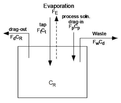 Figure 1: Single Rinse Mass Balance Schematic
where,
- CR = concentration of the rinse tank
- V = volume of the rinse tank
- t = time
- Fp = flow rate of the process solution into the rinse tank (drag-in) Ft = tap water flow rate into the rinse tank
- Fd = drag-out of rinse water from the rinse tank Fw = flow rate of rinse water to waste hold sump Ct = concentration of the tap water
- Cp = concentration of the process solution.
- Fe = evaporation rate1
1 Fe (evaporation rate) for these models will be ignored.
Since we are only interested in the steady state solution (dCr/dt = 0), the change in the tanks volume can be expressed as:
dV/dt=Fp +Ft – Fd – Fw =0 (3)
And equation (2) then becomes:
CRdV/dt =CR (Fp + Ft - Fd - Fw) = FpCp + FtCt - FdCR -FwCR (4)
Steady state conditions make the math quite easy since we are only subject to solving an algebra problem. Thus substituting, it follows then that the General solution for this system is:
Ft = Fp(Cp - CR)/(CR - Ct) (5)
Equation (5) then determines the amount of fresh water needed to keep a single rinse tank at a constant level of “dirtiness.”
III. Model Descriptions
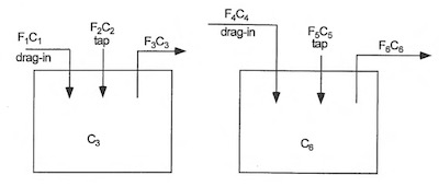 Figure 2: Independent Single Rinses (model no. 1)The first model to explore is two single rinse tanks servicing independent process solutions or what will be called “independent single rinses” as illustrated in Figure 2, where each rinse services only one process solution.
In similar fashion, per the previous section, the general solutions for this rinse system become:
F2 = F1(C1 - C3)/(C3 - C2) (6)
F5 = F4(C6 – C4)/(C5 – C6) (7)
Where there are two independent fresh water feeds (F2 and F5).
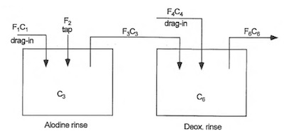 Figure 3: Dependent Single Rinses (model no. 2)Next, consider a system where the rinses are still single for dedicated process solution but one rinse is plumbed to overflow to another rinse. In this case, a conversion coating rinse is selected to overflow into a Deoxidizer rinse. The rationale for this shared rinse system is that the chemistries are similar (chrome and nitric acid) but the conversion coating drag-in is less concentrated than the Deoxidizer solution. Consequently, the supposedly cleaner of the two rinses then flows into the dirtier of the two rinses making what can be called “Dependent Single Rinses” as shown in Figure 3.
The mass balance techniques are still the same, albeit, now a bit more complex algebra is needed for the derivation resulting in the general solutions shown as equations (8) and (9).
C3 = [F1(C2C6 - C1C6) + F4(C2C6 - C2C4)]/[F1(C2 - C1) + F4(C6 - C4)] (8)
F2 = F1(C1 - C3)/(C3 - C2) (9)
And consequently, now there is just one fresh water feed (F2).
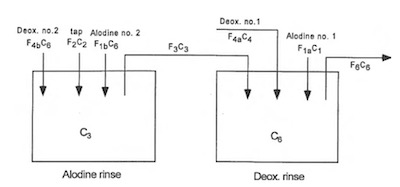 Figure 4: Dependent Shared Double Rinses (model no. 3)The next model worth exploring is where the two rinse tanks are not only plumbed for the conversion coating rinse to flow into the Deoxidizer rinse but the process recipe changes so that these two rinses act as a double counter current rinse but for both process solutions as shown in Figure 4.
The mass balance derivation now results in the concentration of the Deoxidizer rinse, which is the solution to a quadratic (equation 10).
(F4b + F1b)C62 - [(F4b + F1b)(C3 + C2) + (F4a + F1a)(C2 - C3)]C6 + [F1C3(C2 - C1) + F4aC4(C2 - C3) + F4bC2C3] = 0 (10)
Alternatively, the concentration of the conversion coating rinse can be calculated as a quotient having both large numerator and denominator terms as shown in equation (11), if the Deox rinse concentration is held as a constant.
𝐶3 = 𝐶6(𝐹4𝑏 + 𝐹1𝑏)(𝐶2 − 𝐶6) + 𝐶2[(𝐹4𝑎(𝐶6 − 𝐶4) + 𝐹1𝑎(𝐶6 − 𝐶1)] /
(𝐹4𝑏 + 𝐹1𝑏)(𝐶2 – 𝐶6) + 𝐹4𝑎(𝐶6 − 𝐶4) + 𝐹1𝑎(𝐶6 − 𝐶1) (11)
What can be readily seen from equations (10) and (11) is that the rinse concentrations are dependent on each other.
For ease of calculation, it is best for one of the rinse concentrations to be placed mathematically at the desired set value.
Thus, the one flow rate of fresh water needed is simply:
F2 = (F4b + F1b)(C6 - C3)/(C3 - C2) (12)
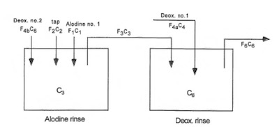 Figure 5: Dependent Double Deox., Single Alodine Rinses (model no. 4)Next, worth assessing is the design on the same two rinses plumbed as before, but with a process recipe change so that the Deoxidizer uses both rinse tanks, but the conversion coating only uses the cleaner of the two rinses as exhibited in Figure 5.
Again, the Deoxidizer rinse concentration is calculated via the solution to a quadratic, per equation 13.
F4bC62 + [F1(C1 - C2) + F4a(C3 - C2) – F4b(C2 + C3)]C6 + [F1C3(C2 - C1) + F4aC4(C2 - C3) + F4bC2C3] = 0 (13)
And similar to the prior model, the one stream of fresh water feeding the conversion coating rinse is:
F2 = [F4b(C6 - C3) + F1(C1 - C3)]/(C3 - C2) (14)
Now with these four models in place, useful interesting perturbations of process conditions can be analyzed for each model.
IV. Process Simulations
As previously mentioned, there are numerous well known methods that either reduce process solution drag-in concentration or process drag-in volumes (Lab data determined that spray rings account for a concentration reduction by approximately one third). For instance, spray rings reduce drag-in concentrations. Reducing drag-in volumes can be accomplished by a) extended drain times3 [6], b) basket or racking re-design, and c) high frequency shake to name a few.
Now much is in place for combinations of process models and input variables to be readily estimated to determine water usage. For each of the three models described (Figures 3-5), the effect of process parameters can be analyzed and compared to the “Independent Single Rinses” configuration (Figure 2).
As noted, there are many ways to reduce rinse water consumption that can essentially either lessen the process solution drag-in concentration (C) or drag-in amount (F). For purposes of analyzing effects, process models can be used to generate quantitative results. For demonstrative purposes, two process parameters are explored that each have four conditions, hence there are 16 results that can be generated for each model.
The use of Spray Rings will reduce the process solution drag-in concentration. The four spray ring conditions are: i) No Spray Rings, ii) Spray Ring on Alodine tank only, iii) Spray Ring on Deox tank only, and iv) Spray Rings on both Alodine and Deox tanks.
Extended hang times will reduce the amount of process solution drag-in. The four hang time conditions are: i) No Drip, ii) Alodine Drip only, iii) Deox Drip only, and iv) Drip on both Alodine and Deox tank.
1. Dependent Single Rinses
As described per Figure 3, the Dependent Single Rinses configuration are plumbed so that the cleaner Alodine rinse overflows into the Deox rinse but the process solution drag-in amount goes only into their respective rinses. Running each process condition through equation (9) results in the calculated percent reductions shown in Table 1.
Table 1. Rinse Reduction from Independent Single Rinses to Dependent Single Rinses
% Reduction
| Double SR | 44.2 | 47.8 | 62.9 | 66.5 |
| Deox SR | 39.4 | 44.9 | 58.1 | 63.6 |
| Alodine SR | 20.4 | 24.0 | 48.7 | 52.3 |
| no SR | 15.6 | 21.1 | 43.8 | 49.4 |
| no Drip | Alodine Drip | Deox Drip | Double Drip |
What can be readily observed is that principal effect has to do with changes to the Deox tank. For this model, that result makes sense because changes are affecting the tank that has a required set-point value of 750 ppm. The Alodine rinse steady state value is a dependent variable and is calculated per equation (8) but is always under 300 ppm.
2. Dependent Shared Double Rinses
As demonstrated in Figure 4, the Dependent Shared Double Rinse configuration is again plumbed so that the cleaner Alodine rinse overflows into the Deox rinse, but also,
the process recipe is altered so that the rinses are akin to a traditional double counter current rinse (DCCR) configuration used by both process solutions. This is not an uncommon practice when the respective process solutions are similar in chemistry. As before, running each process condition through equation (12) results in the calculated percent reductions shown in Table 2.
Table 2. Rinse Reduction from Independent Single Rinses to Dependent Shared Double Rinses
% Reduction
| Double SR | 89.1 | 90.5 | 92.1 | 93.5 |
| Deox SR | 88.6 | 90.3 | 91.6 | 93.2 |
| Alodine SR | 86.8 | 88.4 | 90.6 | 92.1 |
| no SR | 86.4 | 88.2 | 90.2 | 91.8 |
| no Drip | Alodine Drip | Deox Double | Drip Drip |
This model takes full advantage of a traditional DCCR configuration and the model itself is the most powerful contributor to rinsewater reduction. The process parameters of extended hang time and spray rings do not contribute significantly beyond what just processing per a DCCR achieves.
However, this model may raise some concern since the Deox rinse is the first rinse of two rinses for both process solutions. The Alodine rinse is a set value of 385 ppm which corresponds to a pH of 4.0. The Deox rinse is a dependent variable that is calculated per the solution of a quadratic via equation (10); and depending on the process parameter conditions can be upwards of 4000 ppm which then corresponds to a very acidic pH of ~0.9.
3. Dependent Double Deox, Single Alodine Rinses
Whereas the Dependent Shared Double Rinse model has impressive rinsewater reduction values, it does pose a concern that the “Deox rinse” would go to a steady state of having too low a pH. Such an acidic first rinse is not practical for consideration of a freshly conversion coated surface to have even if the duration is very short. Consequently, the last model of interest is analyzed where the plumbing remains the same but the Alodine parts are only using the cleaner of the two rinses, as illustrated per Figure 5. Again, running each process condition through equation (14) results in the calculated percent reductions which are shown in Table 3.
Table 3. Rinse Reduction from Independent Single Rinses to Dependent Double Deox, Single Alodine Rinses
% Reduction
| Double SR | 78.1 | 79.6 | 84.8 | 86.8 |
| Alodine SR | 77.0 | 79.1 | 83.4 | 86.2 |
| Deox SR | 68.7 | 69.9 | 79.6 | 81.2 |
| no SR | 67.9 | 69.5 | 78.4 | 80.7 |
| no Drip | Deox Drip | Alodine Drip | Double Drip |
What can be readily observed is that the principal effect has to do with changes to the Alodine tank. For this model, that result makes sense because changes are affecting the tank that has a required set-point value of 385 ppm which, as before, corresponds to a pH of 4.0. The Deox rinse steady state value is a dependent variable and is calculated per equation (13) and can still run using less than three times the amount of water from that of the original model.
V. Summary
Using mass balance techniques for process modeling immersion rinse operations is effective in guiding chemical process managers on process improvement ideas. Without the need for expensive removal and replacement of entire tanks, process options such as ancillary plumbing for water flow and spray ring alternatives can be examined. Additionally, process modeling can evaluate other ideas that alter the process solution drag-in amounts, such as extended hang times.
Mass balance modeling was demonstrated for four specific process configurations and compared to a theoretical inefficient independent single rinse system. The focus of this paper is not so much to recommend a specific rinse system or rinsewater reduction technique, but rather, to illustrate how process engineers might evaluate any number of rinsewater reduction methods with confidence and relative ease by use of mass balance process modeling.
W. John Fullen has been with the Boeing Company for more than 30 years, at present in the Boeing Research and Technology (BR&T) organization, first in advanced composites but predominantly in chemical technology in support of tankline operations and the Boeing supply base. Prior to that, he worked at H.B. Fuller Co. in the area of adhesives. He holds a B.S. in Chemical Engineering from the University of Minnesota.
References
1. W.J. Fullen, Proc. AESF SUR/FIN 2000, AESF, Orlando, FL (2000). https://www.boeingsuppliers.com/environmental/Modeling.pdf
2. J.K. Unangst & W.J. Fullen, Plating & Surface Finishing, 91 (12), 44-49 (2004). https://www.boeingsupplier.com/environmental/RRCPaper.pdf
3. 20 Ways to Cut Water Usage in Plating Shops; Finishing Technology, Kinnelon, NJ.
4. The Art and Science of Rinsing; AESF Educational Course, Copyright 1992.
5. Rinse Water Contamination, O. J. Hadaller, Boeing Co. MDR 2-36070, 25 June 1974.
6. A Pollution Prevention Resource Manual. https://p2infohouse.org/ref/03/02848.html