A practical review covering the spectrum of energy savings and efficiency improvements for the Type II and III Hard Anodize Processes will be presented.
 Fred SchaedelThere are specific areas when operating together can give anodizing shops from 20%-50% savings. The areas include:
- Modifying anodize bath parameters.
- Using a unique pulse ramp procedure to start each tank load.
- Using a new capacitance shunt discharge system to initiate anodizing at a lower voltage.
Data logger graphs will be presented from production facilities to verify all data presented including energy savings and quality standards.
Introduction
This paper will present and review the important factors with which the anodizer should really be concerned in order to improve quality to a high degree while, at the same time, improving efficiency and saving energy. A major part of the paper will center around the complete spectrum of control factors at the anodize tank. One very important fact needs to be emphasized and remembered throughout this paper: That is – Unless the anodizer familiarizes himself with and uses all of the factors together as they are noted herein, the true great efficiency and energy savings will not be realized. There will also be one practical new development presented in Section V which is very important as related to all other factors operating together to initiate anodizing at a very low voltage.
Let me go back for a short time so that the reader can see where I’m coming from and better understand and appreciate this paper. My past experience in the anodizing field has been #1 – Problem solving (trouble shooting) and #2 – Education (such as process procedure development all centered around the quality control). I remember in the early years or maybe half of my 49 years‘experience everything was centered around quality. However, for the last 15 years in particular it seems like people want it faster at the lowest possible price or good enough to get by, along with energy savings and efficiency – But only when it’s easier and costs less. This can also extend to the supplier products which are purchased with reduced prices and minimum usage ranges established to increase profits but not quality end results. Therefore, problem solving and education were necessary on numerous occasions because the factors and information in this paper were not all used together as a Complete Spectrum Package.
After reading the previous paragraph, keep this in mind throughout this paper. If the proper steps are taken (using all information presented in this paper) to improve quality and reduce process time, the efficiency and energy savings will be there and the cost effectiveness will be realized. These steps will be analyzed in various areas of the anodize process at the process tank. Specific factors will be emphasized in each area.
This paper will focus on 5 particular areas as related to Quality, Efficiency and Energy Savings:
- Chemistry – Specifications – Modified Formulations
- Power Supply Electronics
- Manual / Auto Control Procedures
- Design Factors at the Anodize Tank.
- New Developments
The conclusions in Section VI will note the 25-50% and more efficiency savings which can multiply from one area to another.
I: Chemistry: Specifications – Modified Formulations
Basic Sulfuric Acid Formulation; Additives – Modifiers - Accelerators Basic Sulfuric Acid Formulation
Some of the specification ranges for sulfuric acid are too high for efficiency – too low for various alloys – and too wide open for quality and energy savings. Our pioneers of research and development set up ranges for Type II and Type III anodize 50-60 years ago which in many cases are not acceptable to meet quality and efficiency standards needed today on a continuous basis in production. These old basic ranges were passed on by technical writers who were not aware of technical developments or simply took the easy way out – copy that which worked in the past. This has developed into a real problem. Therefore, after careful evaluation, universal ranges meeting all major specifications will be presented in this section in order to solve this problem.
Various operation ranges for sulfuric acid have been reviewed which date back over 50 years. We have also reviewed numerous Commercial and Military specification ranges in operation10-15. Finally, after recently reviewing over 25 of the latest high tech Aircraft, Aerospace, Military and Commercial specifications, we are presenting the best operation ranges for Type II sulfuric and Type III hard anodize. The operation range Chart/Fig #1 lists all the widest sulfuric acid ranges as they have been pulled from the various specifications. We have noted the best operation ranges underlined for Type II – overlined for Type III and combination Type II-III hard anodize (Type 23).
The anodize industry needs better quality Type II which in many cases should meet the requirements for hard anodize. Also needed is a superior hard anodize, far greater than the present national average. Engineers have been turning away from hard anodize on certain alloys because many anodizers have been producing soft coatings and/or burning alloys like 2011, 2024, 2219, 7075, and 7050.
Additives, Modifiers, and Accelerators
This is one area where quality, efficiency and energy savings can really be improved. I really can speak with some authority here since I have researched and reviewed this area for decades dating back to my first patent application in 19621-5. The additives are not being used at the proper concentration. The highest aircraft specification range is 4– 5% for MAE called out in the Boeing Spec BAC 5821. However, most additives – similar to MAE – should be used 5- 7.5% and higher8-9.
Chart 1: Anodize Tank Operation Rangers
Free Sulfuric Acid:
- Type II – III – 23: {5.0 – [10.0 – (11.0 – 13.5 – 15.5)] – 20.0 % Vol}
- Type II – III – 23: 18 – 20 –25 – 27.5% Wt/Vol
- Type II – III – 23: 180 – 200–250– 275g/l
Sodium Bisulfate: 3.0 – 7.0% Wt/Vol (Check with FCS at APS/ATS)
Additives: 2.0 – 5.0 – 7.5% – (8.0 – 15.0% Conc. Not needed with modifiers)
Modifiers Accelerators: 1.0 – 2.0 – 3.5% (Modifier as presented at Sur Fin 2005)
Temperature: 20 – 30 – 35 – 50 – 55 – 70 – 85 – >110°F
- Type III
- Type II - 23
Aluminum: 3. 8 – 8 – 10 – 15 – 20 g/l max.
Air Agitation: 2.5 – 3.0 – 5.0 CFM / Sq Ft Solution Surface
Current Density: 18 < 20 – 25 – 30 – 35 – 45 – 50 - 60 – 75 – 125 ASF
- Type II
- Type III
Hard Anodize Rate (Type – III – 23):
- 0 mil: 10 – 20 min
- 0 mils: 20 – 35 min
- 0 – 5.0 mil / hr 0 – 15 – 20 mils Plus (Special Process)
Type II Anodize Rate (Type – III – 23):
- CL–1 Clear (0.2–0.4 mil): 10 – 15 min ( 20 – 24 Volts)
- CL–2 Dyed (0.5–1.0 mil): 20 – 35 min (20 – 24 Volts)
- Type 23 (1.5–2.0 mils): 30 – 50 min (20 – 24 Volts)
Dependent upon Alloy
We should also realize that all additives are simply not the same. Some are in fact quite different. This can be verified by a simple quantitative redox titration to simulate the heat absorbance in the pore structure during the anodize process. In addition, the increased conductivity and anodic coating formation early in the anodize cycle can be realized by comparison.
There are modifiers and accelerators now available which can be added to existing additives to really increase efficiency and save energy by absorbing excess heat in the pore structure during the anodize process so that the anodize tank can be operated at higher temperatures up to and over 85oF8-9.
Run most anodize additives at 5-7.5% and four improvements will be noted, dependent upon active additive/modifier conc.:
- Initial anodize will form faster.
- Brighter Dyed Coatings. Improved Final Microfinish.
- Lower Voltage and/or Amperage.
Please note the additive and modifier concentration ranges specified in Chart 1.
We should also note the ranges for temperature, air agitation, current density and aluminum which have been underlined and over lined. The anodize rates will be discussed later. The sodium bisulfate can be added for special coating applications to replace high sulfuric acid and can also be discussed later10.
It should be stressed in closing this section that two ranges have been line indicated for Type II and III anodize respectively. However, both Type II and III can be processed with the same formulation range as indicated.
Finally, I do have one suggestion for those who have the space and finances for a unique set up to really take advantage of maximum quality and efficiency. First set up two tanks for Type II and Type III respectively, then two standby solutions to be used for transfer and/or adjustment. With this system, you have four different process ranges which can be changed and/or adjusted quickly – within 30 min. Any aluminum alloy can now be processed with superior quality and maximum efficiency. I actually set up one particular system like this which was very successful. Standard 2 mil hard anodize coatings can be produced on any and all alloys in 20-30 minutes with superior quality.
II: Power Supply Electronics
Rectifier and Pulse Specifications
Rectifier Types
Standard anodize rectifiers are full wave and should have both constant voltage (CV) and constant current (CC) controls represented by two knobs on the remote control panel located near the process tank. Rectifiers with SCR’s in the secondary are preferred and more efficient for the Type II and III anodize processes. Secondary SCR’s (silicon controlled rectifiers) perform both rectification and control simultaneously giving a sharp SCR turn on time which increases efficiency during the ramping cycle. The voltage requirements for Type II and III rectifiers should be as follows:
- Type II: 24-30Volts
- Type III: 75-100 Volts
Special secondary half wave rectifiers have been used very successfully for both Type II and Type III anodize with excellent efficiency and energy savings1,9. The half wave rectification works very well together with specific additive and modifier chemistry when processing problem or difficult alloys like 2011 and 2024. However, half wave rectifiers should not be used for chromic acid anodize. Use only full wave rectification for chromic acid anodize.
The rectifier voltage specifications should always be 10-20% higher than maximum continuous production requirements. Current should not exceed 85- 90% of the rectifier manufacturer’s rating due to heavy KWH and pulse time on a continuous basis. Even though people may disagree, I have found this to be important when considering rectifiers from all leading suppliers and manufacturers.
Pulse Specifications
High frequency pulse is applicable to only very high current density requirements. Slower low frequency pulse has been found to give the best results with energy savings on both Type II and III anodizing 7-9. There has been a 20-25% or more savings in power noted in numerous cases.
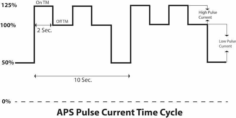
Pulse parameters are all centered around slow (very low frequency) high and low pulse times so that we can take advantage of both relaxation and recovery times8. Pulse specifications are listed here with additions and revisions.
Chart 2: Pulse Specifications
PSR Dwell Time: 0.5- 3.0 min.
Pulse Time Cycle/Duration: 10 – 20 sec
HP - High Pulse Specifications
- HP – On Time: 0.5 – 4.0 sec
- LP – Off Time: 0.5 – 4.0 sec
- HP Current: 10-25-50% Above Operating Amps (During Ramp Period)
LP - Low Pulse Specifications
- LP – On Time: 0.5 – 4.0 sec
- LP – Off Time: Total HP Time Cycle
- LP – Current: 25 – 50 % Below Operating Current
PSR - Pulse Step Ramp Specification
- PSR – On Time (Dwell): 0.5 – 30 Min
- PSR – Off Time: Total HP/LP Time Cycle
III: Manual / Auto Control Procedures
Pulse Step Ramp, Constant Current Density, Amperage Decay: Amperage Drop Off (ADO), Recorders – Graphs – Data Loggers
The process procedure factors, methods and techniques reviewed in this section are very important for the production of high quality anodize with maximum efficiency and energy savings. It cannot be over emphasized that they should be used together as a total package. Be sure to use everything in this section for both Type II and III anodize. If this is done as a complete package, good results will be evident immediately with the first process run. Anodizers should have periodic refresher training (monthly or as needed) to reinforce these procedures.
Pulse Step Ramp
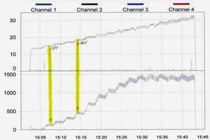 Figure 3: Data logger graph of pulse step ramp regime.We have already stated that very high frequency pulse systems do not give the best end results. Slower pulse interval time (low frequency) is most important during the ramp cycle. Pulse time must be slow (0.5 – 1 – 2 - 4 sec) to allow for recovery time and maximum current efficiency. The high pulse or current amplitude can be 10 – 25 – 50% of the amperage reading for both Type II and III anodizing during the entire ramp cycle. Pulse ramp has been proven to work effectively in most hard anodize systems. However, pulse - step – ramp (with the addition of steps or dwell periods) has been proven to be extremely beneficial in both Type II and Type III anodizing. The steps or dwell periods may vary (from 0.5 – 4.0 min.) depending upon the alloy. Please note one example in Fig 3.
The amperage was in the pulse step ramp mode to 1500 amps. There is a good ampere decay to 1300 amps including low pulse during constant current density.
The wide step time range can be further defined by these suggested operating ranges for different alloys:
Type III (Hard):
- 6061; 0.5 – 1.0 min Steps
- 2024; 0.5 – 1.0 min Steps
- (with 1.0-3.0 min Steps in the critical zone)
Type II – III:
- 380 Die Cast; 2.0 – 4.0 min Steps
- (Due to current drop off not to exceed maximum rectifier voltage)
The total process ramp time is a key issue here along with starting and ending parameters at constant or final running current density. Type II sulfuric anodize should be ramped in the voltage mode over an approximate 10-minute period to insure better dye absorption along with maximum sealing capability.
- Raise voltage manually to 10-12 volts
- Auto Ramp (10 min) to 20-22 volts.
- These approximate values will produce 0.2 – 0.5 mils of Type II anodize in 10 – 15 minutes meeting the requirements of Mil-A-8625 F, Class-1 as well as most other sulfuric anodize specifications.
Maintain constant voltage for 20-30 min and a final anodize coating of 0.6 – 1.0 mil Plus will be formed which meets the requirements of Mil-A-8625 F – Class-2. Maintain constant current density for a total of 45-60 minutes and a final 2.0 mils Plus should be produced which meets the requirements for Type II and III anodize per Mil-A-8625 F.
Hard anodize should always be ramped in the voltage mode so that the amperage developed at a specific voltage is not limited from its naturally steady state (except in the case of surges which are controlled by short pulse ramp steps 0.1 – 0.25 volts). This technique is important. The voltage should always be ramped in short pulses (0.1 Volt or more) but never exactly linear. The voltage is ramped (0.5 – 1.0 – 1.5V/min) to a specific amperage or total running constant current density (30 – 35 – 45 ASF). The current may be alarm set or limited at two or more different set points during the ramp so that the work in process may be checked. This can be done with carefully programmed PLC’s (process logic controllers) which, of course, depends upon the programmer and the procedures set up by the hard anodizer and his experience and ability to run various alloys.
However, an economical digital process controller or relay meter with two alarm set points is quite satisfactory. With some good professional training, the two alarm set points should be satisfactory for all alloys, including 2024 and 7075. There are relatively inexpensive data loggers with real time graphs that can be very helpful when running alloys like 2011, 7050, or A-203. Special pulse ramp procedures are available which are too detailed and lengthy to be included here.
A basic pulse ramp cycle, to and including constant current density, is outlined in steps as follows:
- Load parts into anodize tank - maintain low voltage (3 volts) during loading.
- Manually increase to 10-12 Volts or 10 ASF (25% of RCD- Running Constant Density).
- Turn on / Set Auto Controller 1.0 V/Min.
- Pulse Step Ramp to Running Constant Current Density.
- Continue Constant Current Density to end of cycle. (Cycle completed by Time – Amp Hours – Voltage).
Please note Data Logger graph (Fig. 3).
Constant Current Density
This is an area which is simply not being used and/or properly used by most anodize facilities. Constant current density should be used for both Type II and III anodize, reducing process time by 25-50% in many cases. The following suggested revised ranges are the results of in process production tests and records as related to Quality, Efficiency and Energy Savings.
- Type II Anodize: 18-22-25ASF
- Type III Anodize: 30-45-50ASF
When processing Type II anodize, the anodizer should use pulse-step-ramp to a predetermined voltage (18-22 V.) where the current density will be within the upper limits of the desired range (18-25 ASF) without measuring each part in the tank. When the amperage drops off or decays due to anodic coating formation and build up, the voltage is then increased to bring or raise the current (amperage) back to RCCD (Running Constant Current Density).
Considerable quality and efficiency is gained or lost here dependent upon the constant current density being used properly, including amperage decay which will be discussed in the next section.
Amperage Decay: Amperage Drop Off (ADO)
Anodizing should be run within a constant current density range – not at one exact value or set point – so that the current can decay or drop off (ADO) as the anodic coating builds up. The amperage decay (ADO) can be controlled (5-10-15%) for different alloys by setting the current between two adjustable set points using a process controller or relay meter. When amperage decays to the low set point, it is increased by auto control to the constant current density set point. This can also be noted in Fig. #3. This amperage decay principle should always be used in the constant current density range for all Type II and III anodize. There are benefits to be realized here all related to quality (hardness) and energy savings. One obvious energy savings is the reduced final voltage for hard anodizing.
Amperage decay has always made a considerable improvement whenever it is used to even a limited degree in the constant current density range.
Recorders – Graphs – Data Loggers
Real time graphs of parts in process should be available to the anodizer for Type II and III anodize along with adjustable amperage check points on the graph. The operator can observe and check a production job through the complete voltage – amperge – temperature process cycle. Process procedures can be checked and logged, including any problems and revisions for future reference.
There are various data loggers that have real time graph capability which are relatively economical to purchase. Some units are even available on a purchase lease program.
In review, one must remember that the real time graphic data logger can be very important in certain areas which represent a relatively fast payback.
- Production loads logged on continuous basis (24 hours).
- Efficiency monitored on every tank load.
- Accurate permanent records (graphs) on all special jobs.
- Quality improvements with reference to past graphic records.
Finally, the real time graphic data loggers and recorders are excellent for periodic training programs. Anodizers can be trained to run special jobs with reference to the past performance records readily available in the data logger files.
IV: Design Factors at the Anodize Tank
Bus Bars/Contacts/Racking; Air Agitation; Aluminum Cathodes; Filtration
Bus Bars / Contacts / Racking
There have always been problems with conductivity losses due to inadequate bus bar contacts or corrosion products. I will only note some basic problems and maintenance check points here since most qualified anodizers should be very familiar with this area.
Always make sure bus bars are sized properly with plenty of good flat contact area between joints all assembled with professional techniques and good practice. Contact between rack and work bus bar should be flat and clamped. There are too many anodize facilities with only edge contact between rack and buss bar due to rack/hook design. In this case, double clamp racks until the system can be corrected.
Air Agitation
We have been involved in the design, redesign, and installation of numerous air agitation systems. I would estimate that 75% of all air agitation systems I have reviewed needed modifications which directly relate to efficiency and energy savings. The importance of sufficient even air agitation in the form of tiny bubbles and/or micro-bubbles has been simply overlooked or passed by in many installations. Proper air agitation does improve the chemical reaction efficiency of some additives and a special wetting agent which I shall discuss later.
The improvement in efficiency with proper air agitation can be noticed visually after the air is installed. The operator will witness better amperage decay or drop off during the anodize cycle which indicates faster coating rate.
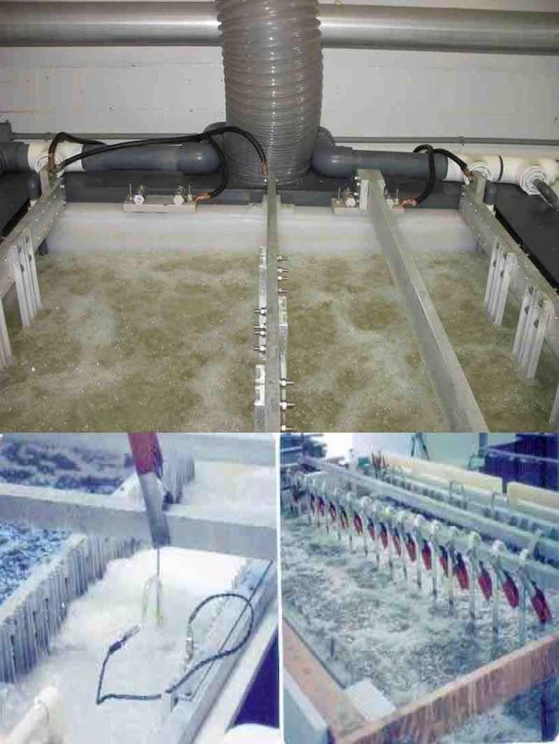 Figure 4: A-B-C Air Agitation SystemsThere are many types of agitation. However, in most cases, air and/or a combination of air and pumping has proven to be the most overall successful. After years of observations and experimental improvements, we came up with the following basic design data for good air agitation in tanks up to ten foot long. Low pressure high volume air from a regenerative blower supplies air to a manifold which feeds riser pipes in all four corners of the tank. The vertical riser pipes connect to a network of half inch Schedule 80 air lines fabricated and drilled according to these specifications listed after Fig # 4 A-B-C.
Air Line Specifications:
- Hole Size: 0.020-0.040 Dia (1/32")
- Holes Drilled Horizontal 1" apart
- 24 Holes per foot (180° both sides of pipe)
- Air Lines 6”-10" apart – length of tank
- Air lines should be 1/2" Schedule 80 PVC
- Outside envelope lines must be 3/4" Schedule 80
- Riser lines must be 3/4" Schedule 80
- Air to manifold – 3 CFM/sq ft solution surface.
The air pressure is critical and depends upon the solution depth and specific gravity along with the total CFM needed and total pipe length from blower to the tank including any ninety degree elbows or obstructions along the main air supply line. Three examples of proper air agitation are included in Fig # 4 A-B-C.
A good wetting agent should be used in the anodizing tank to initiate the formation of tiny bubbles. There are lignin sulfonate products like Orzan that work quite well because they also increase additive and modifier efficiency.
Aluminum Cathodes
Aluminum cathodes should be used in both Type II and III anodize systems. There are specific aluminum alloys and tempers which should be used due to dissolution unless an electric charge is maintained on the cathodes when the tank is not in operation. I suggest 6063 T-6 which is available in most areas. Cathodes are also available which have been designed for better throwing power. In the past, a low cathode to anode area ratio (1:3) has been suggested. I maintain that this ratio can be raised higher (1:1) provided a good additive and modifier system be maintained. The cathodes should be placed evenly along the length of the tank on both sides for even current distribution.
Filtration
It is good practice to have continuous filtration on the anodize tank. This has been proven to improve quality and promote longer tank life by some professional anodizers. Filtration with inside tank and outside tank systems are both being used successfully with two stage filtration. In some cases 5-10 micron filters are being used with the second stage 0.5 – 1.0 micron.
V: New Developments
Capacitance Shunt Discharge – Practical Revision 2; Electro Color / Two Step
Capacitance Shunt Discharge – Practical Revision 2
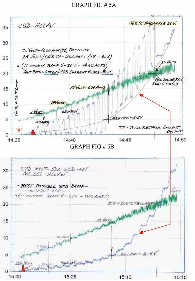 Figure 5: Data logger graphs showing performance of Capacitance Shunt Discharge System (a) in service and (b) off line.I would like to introduce a new development which increases the anodize current flow at the beginning and throughout the ramp cycle. A new CSD or Capacitance Shunt Discharge System has been developed and put into production operating more economical and practical by limiting its use to the pulse ramp cycle (5-20 Volts). The increased current density can range anywhere from 40-150% higher depending upon the system after maximum losses. Two data logger graphs presented here (with the system in and out of service) prove the very significant improvement in efficiency and energy savings.
The system works in theory and practice by discharging capacitance reactance (impedance) on the anodize tank resulting in a higher amperage at the same voltage.6, 8 This new revised system has been used on both half and full wave secondary SCR rectifiers with great success. One good production example is presented in Graphs Figs #5A-B.
It must be also noted that the second set of graphs (Fig #5B: Run with same 1500 amp production load without CSD) are included to verify and prove just how good the system really works in practice as indicated in Graph Fig #5A. Please note the increase in amperage when the CSD is introduced with 25 second repeat pulses. We have checked the percent increase in amperage at various points and listed them here including the maximum possible losses due to bypass current during discharge.
- 4 – 6 Volts (Anodize Initiated)
- 7 – Volts – 140 Amps (3.5% TC) – 75% above 80 A – 40% After Bypass
- 10 – Volts – 280 Amps (7.5 TC) – 180% above 100A – 105% After Bypass
- 15 – Volts – 600 Amps (15% TC) – 200% above 200A – 144% After Bypass
- 20 – Volts – 1440 Amps (36% TC) – 80% above 800 – 61% After Bypass
The anodizer can readily see the current increase results from CSD which represent a very significant increase in efficiency and energy savings. Specifications for specific economical CSD systems available upon request.
Electro Color – Two Step Coloring
I ran some basic tests using CSD in two Electro Color systems. There were significant improvements in three areas:
- Appearance – Brightness
- Micro Finish
- Hardness (Wear Resistance)
This is one area which must be further explored due to the fact that a major problem with Electro Color is Dull Finishes. However, it is evident that the efficiency and appearance (brightness) of all Electro Color systems can be improved using CSD along with all of the other areas reviewed in this paper operating as a Complete Spectrum Package.
Conclusions: Major Benefits Realized
The major benefits realized as they are presented in the conclusions should be considered as a Complete Spectrum Package, all directly related to quality, maximum efficiency and energy savings. Remember – A chain is only as strong as its weakest link.
- The universal chemical operating ranges presented in this paper should be used for all Type II and III anodizing, reducing process time by 25- 50% plus.
- Additives, Modifiers and/or Accelerators should be used whenever possible – checked for efficiency – and maintained at higher concentrations (5 – 7.5% in most cases) which allows higher anodize tank temperature operation (50-85o F Plus).
- A combination Pulse – Step – Ramp including Dwell should always be used at a very low frequency.
- Sufficient proper air agitation in the form of tiny micro bubbles is necessary to allow all other systems to operate properly.
- Amperage Decay must be used in the constant current density area to promote efficiency and energy savings. Current Efficiency is also increased at a lower voltage.
- All alloys can be processed with the same tank formulation. (2011 - 2024 – 2219 – 7050 – 7075 – 7178 – 380 die cast)
- The final microfinish is improved along with brighter dye colors.
- Smut (powder burn) and soft powdery coatings are eliminated even at high operating tank temperatures (70 - 90oF) when other areas and parameters are operating together properly.
- The CSD (Capacitance Shunt Discharge) system improves the efficiency in all other areas including electro color.
- Improved quality, efficiency and energy savings can range anywhere from 25 – 100% Plus depending upon the original system in operation. Additional data logger graphs are available upon request to verify these claims for specific systems in operation.
References
1. F.C. Schaedel, U.S. Patent 3,418,222 (1968)
2. Working K.C., U.S. Patent 3,434,943 (1969)
3. Reynolds Metals Co., U.S. Patent 3,524,799 (1970)
4. Woods, U.S. Patent 3,857,766 (1974)
5. F.C. Schaedel, U.S. Patent 34,152,221 (1979)
6. Kljucaricek et al., U.S. Patent 4,879,018 (1989)
7. Dr. Jean Rasmussen Proc. AESF SUR/FIN 93,P 905-914
8. F.C. Schaedel, proc. AESF SUR/FIN 2003, P 71-84
9. F.C. Schaedel, proc. AESF SUR/FIN 2005, Pulse Ramp Mixed Electrolyte Anodizing
10. S. Wernick, R. Pinner and P.G. Sheasby, The Surface Treatment and Finishing of Aluminum and Its Alloys, Finishing Publications Limited, Teddington, Middlesex, England, 1990
11. Mil-A-8625 F Anodic Coating of Aluminum and its Alloys
12. AMS-2469 G Hard Anodic Coating Treatment of Aluminum Alloys
13. BAC 5821, Boeing, Hard Anodizing
14. APS PS-7167, Alpha Process, Anodic Coating Process Standard
15. Numerous Process Specifications and Procedures Limited Supplier List as Follows:
- Boeing: McDonnell Douglas Long Beach Rockwell Defense Systems; McDonnell Aircraft, St. Louis; Mesa- McDonnell Douglas Helicopters Plus Three Other Boeing Facilities
- Bell Helicopters
- Lockheed Martin (3 Division Specs.)
- Northrop Grumman (3 Division Specs.)
- Parker Aerospace (FCHS)
- Pratt and Whitney
- Sikorsky Aircraft Corp. (United Tech)
- Five Specifications outside U.S.A. (As related to Operation Ranges)
Fred Charles Schaedel is President of Alpha Process Systems in Westminster, California. Visit http://www.alphaprocess.com. He started Anodizing and Plating at Hudson Plating Works and Harshaw Chem. Co. in Cleveland, Ohio, in 1957. He has developed specialized anodize additive modifiers, and pulse ramp systems — including waveform technology — and established training programs in the anodizing industry dating back to 1962.