Maintaining surface finish quality during the complete anodize cycle has long been a major problem for the metal finisher.
 Fred SchaedelNow, after years of applied problem solving methodology, we present improved, maximized and concentrated amino activation and protection for the production anodize line. This newly formulated amino complex chemistry has been optimized to improve efficiency and promote Total Quality Improvement (TQI) for all aerospace alloys including the complex / difficult to anodize 2000 / 7000 series (2219, 79050 etc). Presentations will cover the following insights and improvements: 1) Amino complex alloy degradation protection during pre-cleaning / deoxidizing. 2) Surface activation and protection during the total exposure to the anodize tank electrolyte. 3) Early initiation and promotion of proper pore structure development (2 – 5 volts) for faster more compact anodize buildup. 4) Retaining activation and promoting more efficient sealing for corrosion resistance. Test panel exposure photos and data logger graphs will indicate active surface protection, energy savings and reduced process time for Type IC, II, IIB and Type III (Hard) anodizing.
I. Background
My associates and I have constantly strived to improve the anodize process. For me this began in 1957 when I started working for Hudson Plating Works in Hudson Ohio. I moved to California in 1962 (53 years ago), and while working for NASA, Northrop, Boeing and Lockheed at Schaedel Laboratories, I became involved in numerous problem solving situations, all associated with the anodizing and plating industry. Major aircraft companies, along with my anodize customers, brought numerous problems to our “think tank” consulting group alliance, which we established as the secret PAC (Precision Aerospace Consultants – 1965). Five of our original 15 members were from major aircraft and aerospace facilities. I especially enjoyed my brain storming sessions with Ray Wimer of The Boeing Company, mainly because of his dedication to Total Quality Improvement (TQI) (1970 – 1985). In 1990, PAC became Anodic Technical Services Group Alliance in where my dedicated customer members shared their problem solving situations, many of which are related to this paper.
The key to problem solving situations is normally centered around, or a part of, the tank chemistry, the electrical power supply waveform / pulse or the process procedures, which we have written, studied and revised for 53 years. This is how the Complete Spectrum Approach / Package (1990) was conceived and still continues to be improved as the Complete Spectrum Plus (2006 forward).
Since 2000, we have presented / participated in over 25 specialized technical papers, forums, seminars and workshops – all centered around the Complete Spectrum approach to anodizing for Total Quality Improvement (TQI). Five particular papers represent a review and basic background leading up to this paper:
- Complete Spectrum Guide to Top Quality Anodizing – AESF 2006
- Anodizing Difficult Alloys – 50 Years Problem Solving (Abbr) AAC 2010
- Aerospace Anodizing in a Non Chrome World AAC 2013
- Unique New Thin Film Technology (Abbr) – NASF 2014
- Insights in the Development of Anodizing Complex Alloys (Die Cast) AAC – 2014
After reviewing past papers, we have found two factors which continue to be increasingly more important for aerospace anodizing TQI. They are activation and protection of the bare aluminum and final anodize finish and are the keys to our present and future Applied Research and Development.
One of the special members of the Anodic Technical Services Group Alliance (San Diego) has recently closed after 65 years of service to the metal finishing industry. They started anodizing in the 1960s with a state of the art process (at that time) using Lincoln Generators.
For the past 21 years, they have been the major West Coast facility for testing and improving our Complete Spectrum Approach, including APCD and our special procedural requirements. There were numerous test sessions over the years using their hard anodize tank, with the full cooperation and personal assistance of Luis Robles, Secundino Naranjo, and Paul Hummell. This facility produced the finest hard anodize with our complete spectrum package. The ATS pulse unit, auto controller and APCD (in the photograph) were updated four times over the past 21 years. This San Diego facility excelled in many essential areas.
- Running difficult alloys 2024, 2219, 7050
- Hard black anodize on commercial and military fire arms
- Hard Anodize on underwater monitoring equipment (similar to Sonobuoy Tubes – NUWS)
- Running superior hard anodize @ 30 – 65 F
- Proving the validity of mixed electrolyte chemistry from 2003 – 2015 (for 12 of the last 21 years)
The use of mixed electrolyte chemistry will be stressed in all future papers due to the proven success in San Diego along with other quality aerospace process facilities in Southern California. We will now share our tartaric / oxalic / citric blended addition, for all Type IC, II, IIB and III hard anodize, as Type 123. This will be the way of the future – and for now, the future is the select few.
In addition, another anodizing facility in Central California has been using our ATS/APS Purification System for Dissolved Aluminum Removal since 1995. After working through the initial glitches their six anodize tanks have been treated numerous times over the past 17 years, with very little additive or mixed electrolyte loss. Their main hard anodize tank operated for over 10 years before it was dumped and a new, larger tank was installed. This long life can also be attributed to early testing of systematic additions of Amino Complex Chemistry, which gave us new insights and lead to ACP and ACXP.
II. Introduction
Maintaining surface finish quality during the complete anodize cycle has long been a major problem for the metal finisher. We will present new improved maximized and concentrated Amino Activation and Protection (ACXP) for aerospace anodizing with Total Quality Improvement (TQI).
This paper sets forth insights, along with proven technology, for the key factors the Aerospace Anodizing Industry needs right now – and will need into the future for problem solving situations and Total Quality Improvement (TQI).
These factors, which tend to be overlooked are as follows:
Activation:
- Surface activation after each cleaning step.
- Maintaining an activated surface from the deoxidizer to the anodize tank. Activation during exposure to anodize electrolyte prior to ramp cycle.
- Activation during the ramp cycle.
- Activation throughout the entire anodize time cycle,
- All can be accomplished using Amino Complex Ion Protection (ACXP)
Protection:
- Protecting the bare aluminum against degradation and surface defects.
- Protecting the Anodic Surface during total exposure to anodize electrolyte.
- Protecting the Anodic Surface during total anodize ramp and run cycle.
- Protecting the anodized surface after anodize to the seal tank.
- All can be accomplished using Amino Complex Ion Protection (ACXP)
Promotion:
- Promotion of proper pore structure development preceded by ….. Promotion of ATS Anodize Procedural Requirements.
- Promotion and initiation of anodize at a lower voltage (2 – 5 volts). Early at the beginning of the ramp cycle.
- Using ACXP and Anodic Pulse Capacitance Discharge (APCD)
- All can be accomplished using Amino Complex Ion Protection (ACXP)
We have improved, maximized and concentrated this Anodic Complex Protection, designated as (ACXP) for 2015. Our ACXP chemistry has been very effective when dealing with the following recurring anodizing problems and solutions:
- Degradation of aluminum / anodize finish – due to acid overexposure
- Extended times required during loading and unloading anodized tank
- Adhesion and Adhesive Bonding properties
- Fatigue strength reduced on thin films – Type IC (ACXP reduces acid attack before and after anodize cycle.)
- Pitting and associated blistering
- Burning (Types II and III) (poor heat dissipation)
- Soft and powdery coatings (poor taber results)
- Poor dye capability
- Porosity bleed-out (Associated Pits - 380 die cast)
- Poor sealing capability
- Masking failures (breakdown / edges)
III. Mixed Electrolyte Chemistry
We started using a Sulfuric – Organic Mixed Electrolyte in 1991 when we developed our Modified Oxalic and Type IC for a Silicon Valley project. Since then we have proven that Mixed Sulfuric – Organic Electrolytes are very beneficial for proper pore structure development, which can be critical in Aerospace processing. Our preferred mixed electrolyte is composed of a blend of Tartaric, Oxalic and Citric acids. The exact formulation is available through Anodic Technical Services. These Carboxylic Acids are always beneficial in any Type IC, II and III anodize tank. Also, our ACXP contains a Polycarboxylic Complex which makes it an integral part of the final Sulfuric – Organic Electrolyte.
Our Amino Chelate Complex Protection (ACXP) performs five separate functions when added to the anodize tank and during the anodize cycle:
- Protects the bare aluminum / anodic surface from acid degradation before ramp cycle begins.
- Activates the surface during the ramp period to initiate proper pore structure development. “All of the good or the bad is done during the first few minutes of the run”
- Absorbs excess heat / energy in the pore structure with 300% greater efficiency than any other MAE type additive.
- Serves as a very active and efficient primary or secondary electrolyte.
- Finally, the new improved ACXP for 2015 acts as a super corrosion inhibitor, reducing acid attack and field effect dissolution on all aluminum alloys, including 380 die cast.
If the acid attacks the surface before voltage ramp – up, or after the voltage is lowered at the end of the anodize cycle, this could cause surface finish degradation below the pore structure. The result would be reduced fatigue strength on structural aerospace parts. The ACXP serves a dual purpose. It greatly reduces the acid attack and improves pore structure development. We accomplish this by adding an Aromatic Hydroxy Carboxylic Acid to our Amino Carboxylic Modifier. There are several acids that will perform in this capacity. Some examples are listed below.
- Hydroxy Benzoic Acid
- Sulfo Salicyclic Acid
- Gallic Acid
- Quebracho extract (highly soluble)
While working with John Mck Ballou, we anodized with the Quebracho extract in 1967. Hydroxy Benzoic Acid is noted in his US Patent #3,434,943. The Quebracho Extract contains a more soluble Hydroxybenzoic Complex which dramatically reduces sulfuric acid attack and dissolution.
The ACXP and Amino Complex Chemistry has been incorporated into the ACEA Activator / Electrolyte and can be used in all Sulfuric Acid anodize solutions, along with some alkaline based anodize solutions. (These may appear in future papers.) The concentration varies, depending upon the sulfuric electrolyte acid concentration. Please note the preferred operating ranges for Aerospace Type IC, listed in red in the following chart:
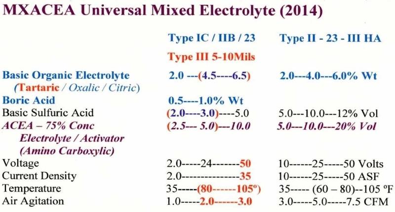
We have used 2 – 3 % ACXP as one single additive, without ACEA, for Type IC, II, IIB, and Type 23 anodize. Activation and protection was proven before, during and after the anodize cycle. It should also be noted that a dip or spray rinse (2 – 3% ACXP) before or after the anodize cycle, will prevent any degradation of the finish for extended periods of time (5 - 15 - 30 minutes). We are introducing a manual / automatic ACXP spray rinse after deoxidize and after anodize at 3 customer facilities.
Testing Amino Complex Protection (ACXP) / (ACP): 2014-2015
Exposure time to the sulfuric acid anodize electrolyte before initial voltage is applied, must be kept at a minimum (30sec.). Any prolonged exposure / acid attack could cause serious degradation of the surface, leading to other surface defects after the anodize cycle. Pitting and/or blisters are obvious examples of these later surface defects. Therefore, Anodic Complex Protection (ACXP) was tested in the same manner that it protects parts in the anodize tank – before and after 5 – 10% additions of the ACP and ACXP. The tests run using ACP on 5% sulfuric, 10% sulfuric and TSA anodize noted in the photograph (designated test panels 4, 5, 6) indicate good protection. The anodize tanks used represent average production with heavy metals and other contamination within maximum specification limits.
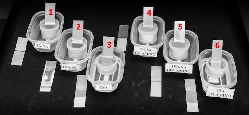 Test Panels 4, 5, 6 (protected with Amino Complex) indicate light etch / attack. Very slight etch / no smut on TSA Amino #6 (after 24 hours). Test Panels 1, 2 indicate definite attack (slight etch on TSA #3)
Anodic complex protection (ACXP) was tested on Type II, Type III and Boric Acid anodize tank solutions after heavy production (2 – 5 years), with heavy metals at a maximum and / or over specification limits. All tests were conducted using 7075 test panels (1 x 4 coupons). This represents the alloy series used in the aerospace industry, which is the most susceptible to corrosion.
The attack, corrosion and immersion plating were tested by immersing test panels before and after 5 – 10% additions of ACXP, without rinsing, allowing the acid anodize electrolyte to dry on the test panels after the designated immersion times. These are noted in the photographs designated BSA / ACXP Testing and Type II / III ACXP Testing.
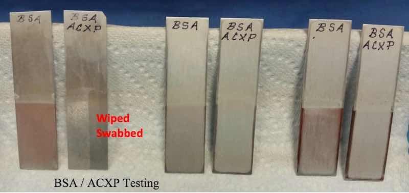
Please note, the BSA test panels (noted BSA / ACXP) protected with ACXP have no corrosion products after 2 - 6 hours, with very slight immersion copper plating after 6 hours and finally, allowing the acid electrolytes to dry on the panels after 24 - 48 hours.
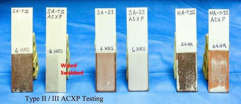
The Type II / 23 / III electrolytes were tested numerous times with immersion plating flaking / falling from the panels in some cases. The Type II / III photograph shows no corrosive attack or pitting where the panel was allowed to dry after 6 to 24 hours in the anodize electrolytes. Please note the panel that was wiped and swabbed with DI water several times to remove the dry immersion plating – no pitting was visible under magnification.
Please note the extreme difference in the heavy production hard anodize tank before and after the addition of ACXP. The copper immersion plating was adhering to the point where this would represent a feasible way to remove excess copper from a production Type II and/or Type III anodize tank in heavy production. We are currently considering the design of a continuous operating cell for this purpose.
The next step was to improve and concentrate the ACXP for critical aerospace structural parts, and continue to make the chemistry more economical in areas where it is most needed on the process line. After reviewing present day process procedures on the anodize line, the ATS Group noted three areas which always need improvement:
- Fastest activation with maximum protection possible on 2000 and 7000 series alloys
- Better activation and protection even in high production anodize tanks (after heavy metal buildup over 150 ppm)
- Micro-finish loss after extended exposure to anodize electrolyte
To better address these issues, we have developed a more concentrated metal complex for 2015 which we have designated as ACXP – 787TX and 787AE and tested on the following three groups of specimens:
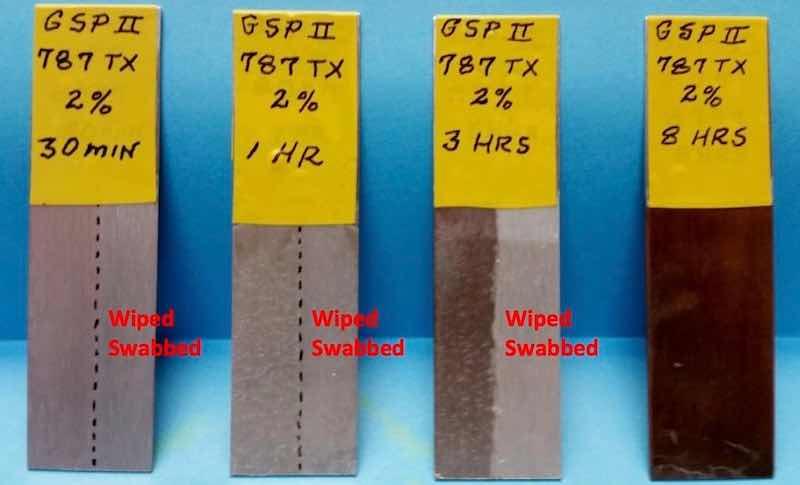
Group 1: Four 7075 test panels were immersed into a Type II anodize tank solution, high in heavy metals (with and without 787TX). After removing the panels from the anodized tank solution, three of the panels were swabbed with DI water on the right side of the panel. Please note after 30-60 minutes, the panels immersed in the anodize electrolyte protected with 2% 787TX showed only slight sulfuric acid attack.
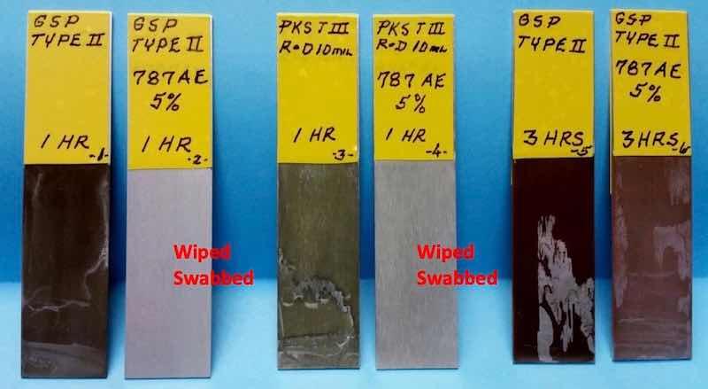
Group 2: Six 7075 test panels were immersed in two different anodize tank solutions (Type II and R&D Type III), both high in heavy metals (with and without 787AE). Four of the panels (numbers 1, 2, 3, and 4) were removed after one hour. Numbers 2 and 4 were swabbed on one side with DI water. Please note, after one hour the panels immersed in anodize electrolyte protected with 5% 787AE show no significant attack. Panel numbers 5 and 6 were removed after three hours. Panel number 6 shows 60-70% less etch attack due to the protection afforded by the 787AE.
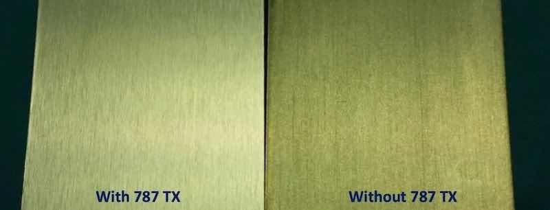
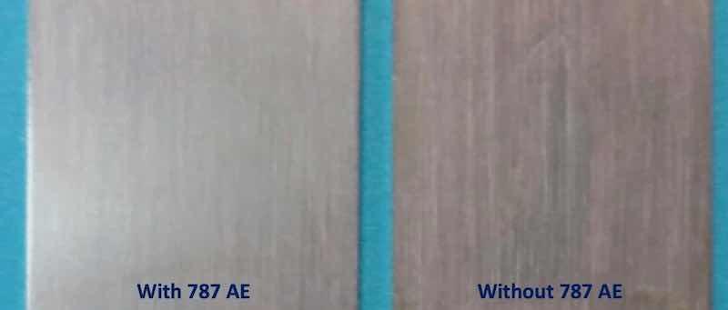
Group 3: Micro-finish comparison tests were done after extended exposure to the anodize electrolyte with and without 787AE. After 30 minutes exposure to the anodize electrolyte it is evident that the panels protected with 787TX and 787AE have a much better micro-finish. This is evident in the following photo which was been blown-up 150%.
The ACXP chemistry is most important for protecting structural aerospace and all anodizing when quality, efficiency and energy savings are important as related to the following three factors at the anodize tank:
- The time period is not as critical before the application of voltage / current. This can be 1 – 2 minutes instead of ASAP, to allow for part positioning, clamping, etc.
- Ramp can and should be started at a low voltage (2 volts) and/or 3 – 5 ASF without basis aluminum and / or anodic coating degradation.
- Anodize parts should be removed from the anodize tank and rinsed ASAP, which has always been a problem. Tests have shown this can be extended to 5 – 7 minutes after the current (amps) is stopped without coating degradation, when using ACXP, allowing the anodizer the leeway sometimes needed with procedural requirements.
Endothermic Electrolyte Chemistry:
Maximum complex ion endothermic heat absorption within the pore structure has always been one of our most important contributions to the anodize industry. However, the sulfuric acid attack is most always in the pore structure, before the ramp cycle starts. AXCP provides a dual function – surface protection and endothermic heat absorption and is effective in these three areas:
- Reduces acid / electrolyte attack to a bare minimum during loading of anodize tank and before voltage is applied.
- Reduces acid / electrolyte attack at beginning of the ramp cycle (1-3volts).
- Reduces acid / electrolyte attack to a bare minimum after the anodize cycle and before the anodized parts can be immersed in the rinse tank.
Also, the addition of ACXP promotes and maximizes the efficiency of MXACE and Conc MXACE in the anodize tank.
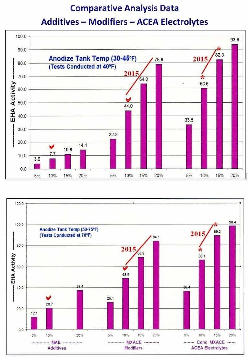
The bar graphs in Fig. #1 and #2, which have appeared in other papers, represent a comparative analysis of the heat absorption of sulfuric / organic mixed electrolytes and modifiers. Please note the red checks designating 10% MAE, 10% MXACE and 10% Conc. MXACE. It is obvious from these graphs that the MXACE and Conc MXACE have greater heat absorption in anodize tanks from 30 – 75 °F than any traditional MAE and this will only be enhanced by the addition of ACXP. Economical mixed electrolyte chemistry and ACXP (for 2015) will provide increased heat absorption and faster anodize buildup. This will make it much more affordable to operate in the areas noted on the bar graphs.
Please note that ACXP integrated into MXACE chemistry also allows the anodizer to use slow pulse and APCD with the following advantages:
- Customer parts protected against acid attack during prolonged loading of anodize tank.
- Pore structure initiated at 2 – 3 volts for all types of anodize.
- Faster anodize build-up for maximum efficiency.
- Anodized parts protected against acid attack after anodize and before immersion in the anodize rinse tank.
- Room temperature operation for Type IC, II, IIB, 23, III and heavy thickness hard anodize (SHA).
- Best Dyeing potential for all coatings
- Better sealing of IC, II, IIB, and all dyed coatings.
IV. Power Supplies: Rectifiers
The standard power supply used by most anodizers is full wave, three phase with constant voltage (CV) and constant current (CC) controls which is suitable for most aluminum alloys. However, for greater efficiency, the following design features need to be specified:
- Rectifier should be capable of starting at an initial setting of 0 – 1.0 volt maximum. This is critical for proper pore structure development.
- A secondary transformer center tap should lead directly to the negative aluminum cathode (No Full Wave Bridge).
- Rectifier should be secondary SCR to perform both rectification and control.
- Rectifier should be protected against excess ripple, voltage / current spikes and deviations. This can be accomplished with a fixed resistance bank or the FCD unit used for APCD. FCD and APCD have been discussed in past papers. This is an integral part of the complete spectrum approach – electronics.
Special half wave rectifiers are preferred for aerospace hard anodizing 2000 / 7000 series alloys and heavy thickness salvage hard anodize (SHA). Also, the following design features and additions should be made to the rectifier:
- Rectifier should be capable of control from 0 volts forward/No Surges.
- The Zig – Zag design should be used for the transformer secondary.
- A resistance inductance load should be connected across the rectifier output (10 – 25% of the load). The FCD unit used for APCD has been designed to meet this capability, along with the following advantages:
- Removes voltage spikes & deviations
- Initiates anodize at 2 – 5 volts
- Initiates higher current density at lower voltage
The integration of APCD operating, along with ACXP, has been very beneficial for anodizing 7000 series alloys. The activation and initiation of anodize build-up at 2 – 5 volts has been proven to be very beneficial in three areas:
- Adhesive bonding
- Hardness
- Final sealing / corrosion resistance
V. Auto Ranging Variable Pulse Power Package:
The APS Group continues to present new improved Anodic Pulse Technology which has been tested and proved in actual production on the anodize line. Results have shown our new ACXP to be a very important addition to Pulse – Step – Ramp (PSR) and Quick Step Ramp (QSR), along with Quick Step Ramp Dwell (QSRD) in these important areas:
- Alloy protection before starting ramp cycle (during tank loading)
- Surface finish activation before starting ramp cycle.
- Anodize initiated at lower voltages ( 2 – 5 volts) (Due to ACXP and APCD working together)
- Anodic protection during long extended ramp cycles.
- Anodic surface protection after completion of total anodize ramp and run cycle.
In addition, with ACXP and APCD working together, the pore structure development and final anodize finish have shown marked improvements in the following areas:
- Superior adhesive bonding applications Excellent dye absorption
- Improved sealing and corrosion resistance
- Variable Pulse Types and Stages/Periods:
The following improvements began with the 1968 Patent, followed by Applied R&D, supplier demonstrations, installations (1980 – 2000), and refinements since 2003 with presentations, technical papers and workshops.
Variable Pulse Types:
- Voltage / Current Pulse – Step – Ramp (2003 – 2015)
- Auto Ranging Voltage / Current Pulse 2011
- Auto Ranging APCD Current Pulse – FCD 2012
- Low Voltage – Quick Step Ramp / QSR 2014 / 2015 Anodize Initiated / Protected – ACXP @ 0 – 2 – 5 Volts QSR Promotes Pore Structure Development (2 – 10 Volts)
Variable Pulse Stages/Periods:
- Activation Pulse Stage – Type A (Protected Using ACXP)
- Bonding and Conditioning Pulse Stage – Type BC
- Current Density Pulse at CCDR Stage – Type CCD CCDR – Constant Current Density Ranging
VI. Process Procedure Requirments
This is a very important part of The Complete Spectrum package and must be promoted and included in all future papers. These eight requirements / concepts represent problem solving technology and methodology good anodizers know as the secrets to TQI.
- Activation – Voltage / Current / Pulse Period
- Pulse – Step – Ramp / Slow APCD – PSR / QSR
- Dwell Times – Increased (3 – 7 min) for 4 – 10 mils (For Proper Pore Structure Conditioning)
- Amperage Decay or Drop Off (ADO)
- Constant Current Density Ranging (CCDR)
- Process Time vs. Ampere Hours
- Real Time Graphic Observation (Monitoring – Analysis – Reproducibility)
- Current / Voltage Spikes & Deviations (removed using FCD) (low voltage anodize initiated by FCD and APCD)
Quick Step Ramp (QSR) has already been specified as the preferred ramp technique for aerospace anodizing Type IC, Die Cast Alloys and wherever thin film pore structure and/or adhesive bonding are critical.
Dwell times and amperage decay (ADO) have become increasingly more important for aerospace anodizing TQI. They should always be used for all Type II, IIB and III hard anodize during pulse-step-ramp and Constant Current Density Ranging (CCDR) to the end of the anodize cycle. Remember – the power supply (rectifier) must be operated in the voltage mode (CV) when increasing amperage and most importantly to allow the amperage to decay (ADO). When ADO is observed, the anodic oxide is building up in a proper nanoscale fashion. The number of dwell periods are dictated by the ADO and well established process procedures. The dwell times listed are suggested / preferred for Type II and III anodizing difficult to run alloys.
- 2000 series alloys: 1 – 4 min dwell
- 7000 series alloys: 30 sec – 2 min dwell
Constant current density ranging has been the major solution to numerous problem solving situations. A steady constant current should never be used for Type II – III anodizing. The amperage must be allowed to drop off 5 – 20% after reaching constant current density and then increased (reset) by increasing voltage. Hence, the code name CCDR – constant current density ranging. CCDR should always be used when anodizing 7000 series alloys to aerospace specifications.
Real Time Graphic Observation (Monitoring and Reproducibility):
The ATS Group is now promoting Affordable Real Time Graphic Observation for all aerospace anodizing. It can not be over emphasized how important real time graphic data loggers are for improving quality, efficiency (reduced time) and energy saving (reduced KWH). They can be a real educational tool when anodizing difficult alloys such as 2024, 2011, 2219, 7075 and 7050. A potential burn can be detected early during the ramp cycle. With early detection the part may be saved for evaluation and rework. Expensive aerospace parts can be monitored on a continuous basis for ADO during dwell periods with calculated current density changes made while the real time graph is observed during the entire process run. My personal graphic data logger equipment has been an extremely useful tool for training and problem solving situations which could not be replaced by any other equipment available.
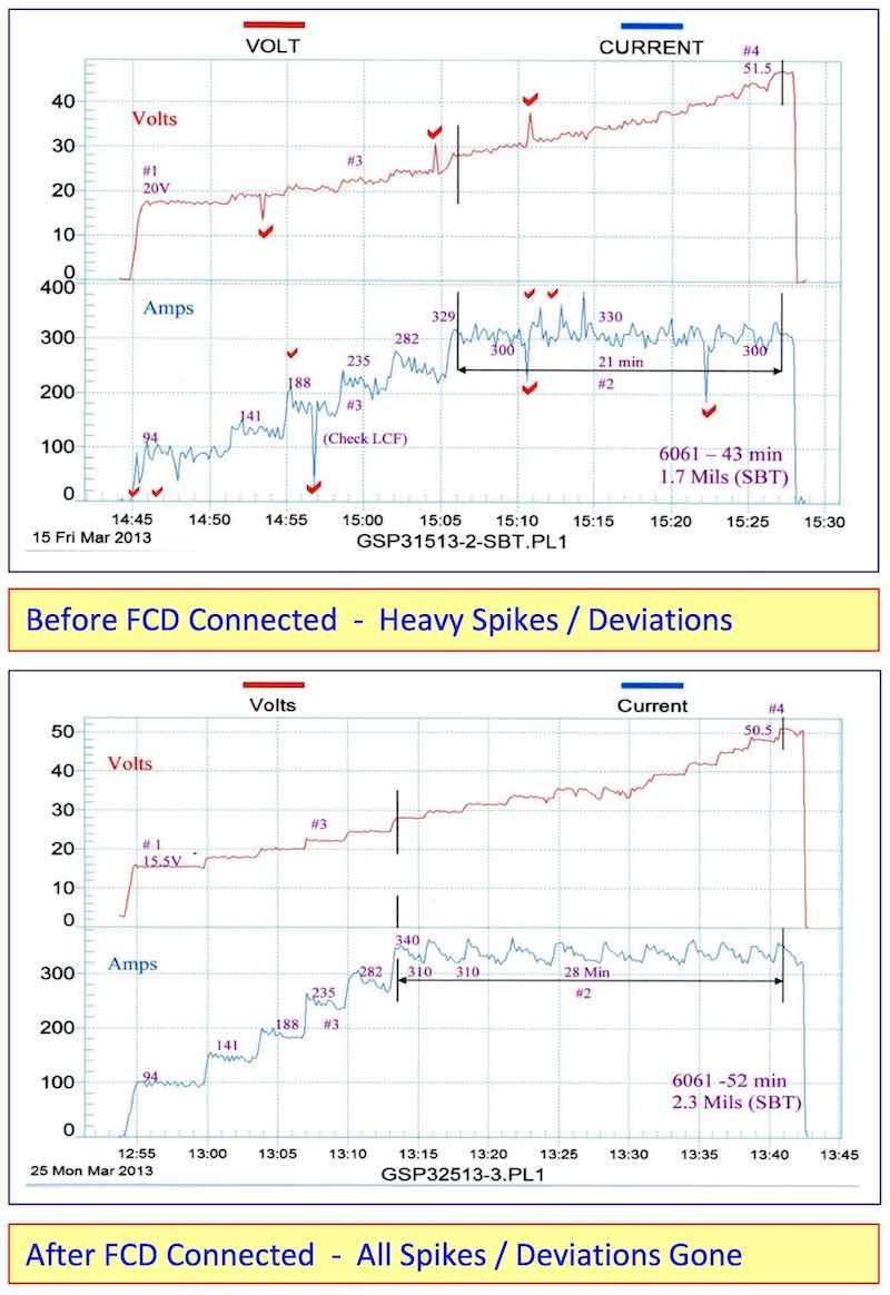
Current and/or Voltage Spikes and Deviations are usually a malfunction within the electronic power package. The fixed capacitance discharge (FCD) bank will remove these spikes as it is clearly indicated in the accompanying before and after graphs. The FCD bank (Without Pulse or APCD) was connected to an older rectifier (25 years) and a sonobuoy tube was run at 30 – 35 ASF. It was then compared to a previous identical run with the FCD bank disconnected. Remarkably, all of the voltage spikes and deviations have been removed. The following improvements were also noted due to fixed capacitance discharge.
- Anodize initiated (5-10 ASF) at 15.5 volts as compared to 20 volts
- Running time at CCDR extended 33% longer before reaching 50 volts
- Anodize coating thickness was 2.3 mils as compared to 1.7 mils
The results are clear, the fixed capacitance discharge (FCD) increases the amperage and current density at a lower voltage and throughout the anodize run.
VII. Data Logger Graphs
The ATS Real Time Data Logger Graphs represent one of our most important contributions to the anodize industry. We are promoting a new type of Real Time Data Logger system that can also be used as a semi-automatic controller with better results. The data logger graphs presented in this paper are as follows:
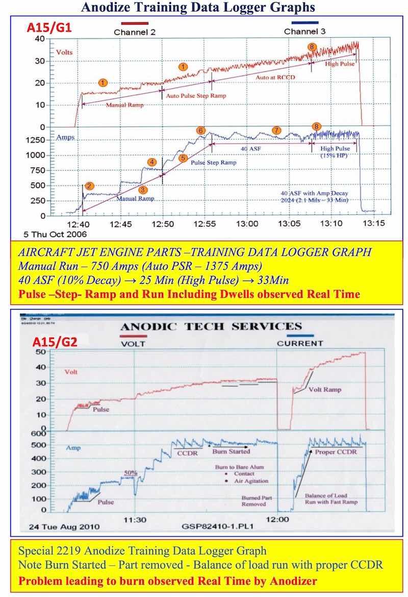
- AAC15-DLG 1, 2: Anodize Training Data Logger Graphs: Pulse-step-ramp and run can be observed real time including any changes that had to be made during the process run. Problems leading to burning can be observed/detected quickly - saving expensive aerospace parts.
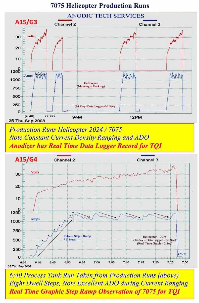
- AAC15-DLG 3, 4: 7075 Helicopter Production Runs: Data logger graphs for all 7075 production runs are stored for evaluation and future reference. The anodizer can evaluate each production run (real time) for proper PSR, Dwells and ADO.
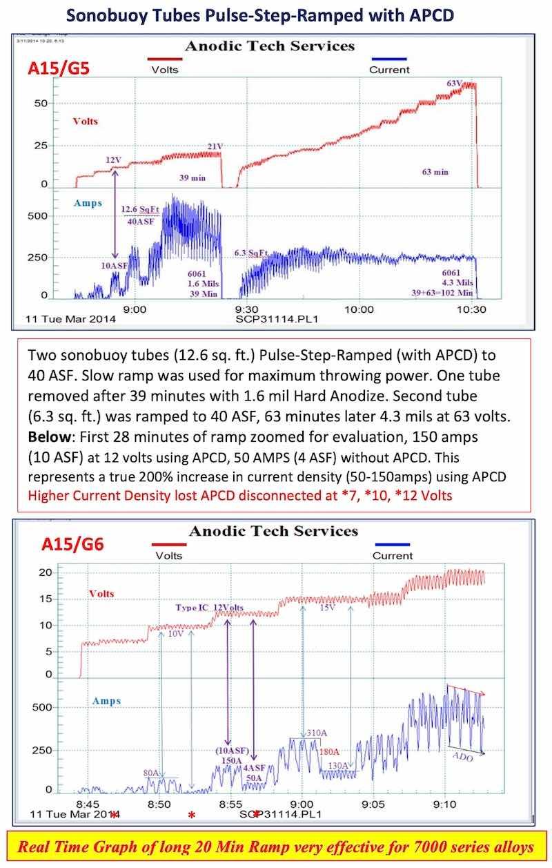
- AAC15-DLG 5, 6: Sonobuoy tubes – PSR with APCD: APCD and PSR can be evaluated real time showing the savings during the ramp cycle.
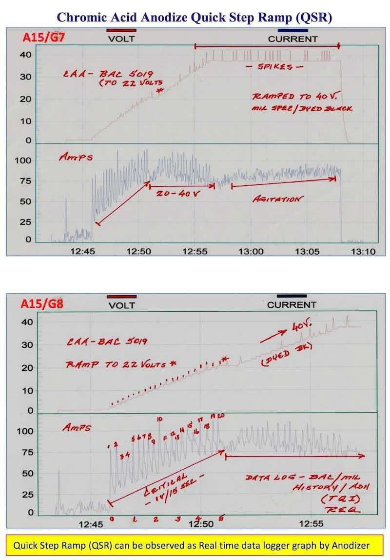
- AAC15-DLG 7, 8: Chromic Acid Anodize - QSR - BAC 5019: Real time graphic data logger graphs represent the best guarantee that the quick step ramp (QSR) was run properly. We believe there should be a permanent real time graphic data logger on all Type I and Type IC anodize tanks when processing aerospace parts.
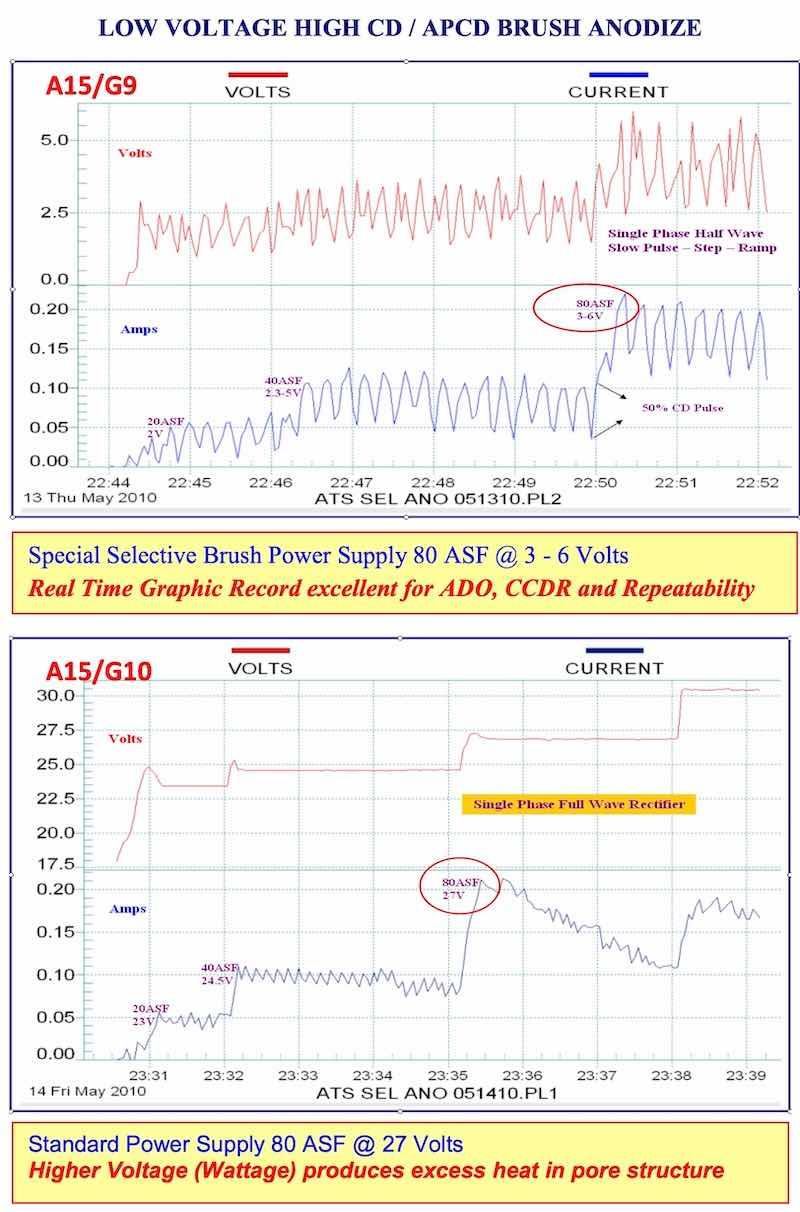
- AAC15-DLG 9, 10: Low Voltage High CD/APCD Brush Anodize: This represents APCD at its best. A very small bore was brush hard anodized at 80 ASF and pulsing at 3-6 volts. Real time graphic observation enables the anodizer to maintain accurate voltage and pulse control on a continuous basis.
VIII. Applied R&D For The Future – Now
Now, the push for the ATS Applied R&D will be centered around activation, protection and promotion of the procedural requirements, while using mixed electrolyte chemistry and the complete spectrum plus. We will also go back to using anodic test cells, which will soon be available to the anodizer for calculating additions.
We will strive to complete areas in our original abstract which were not completed due to time factors. Also, some areas were not covered thoroughly enough for published results. Hopefully, we will complete these tests in another West Coast ATS/APS facility and with the help of Ivan, Tim and Julio. In addition, we will continue our East Coast Applied R&D at our New Jersey ATS/APS facility.
IX. Conclusions
- New concentrated Anodic complex protection (ACXP) activates and protects the base aluminum and anodizing surface before, during and after the ramp period and throughout the entire anodize cycle to the rinse tank.
- ACXP serves a dual purpose in the Anodize tank: a. Reduces acid attack at the anodize surface; and b. Improves pore structure development.
- New ACXP for 2015 (ACXP-15) has been improved for the activation and protection of 7000 series aerospace anodizing.
- ACXP is very effective for thin film anodizing (Type IC), where adhesive bonding on aerospace assemblies is a critical issue.
- ACXP maintains a better microfinish throughout the anodize process cycle including sealing.
- ACXP improves the quality of the anodize pore structure during extended ramp periods for 7000 series alloys.
- ACXP and APCD promote faster anodize buildup reducing the total anodize time cycle.
- ACXP and APCD used together initiate anodize at a lower voltage (2 – 5 volts).
- ACXP and APCD used together prevent degradation of the anodic coating before and early during the anodize ramp cycle.
- ACXP is very effective preventing surface finish degradation for BSA Anodizing (Boeing), TSA, and mixed electrolyte anodizing where fatigue strength is a critical factor.
- ACXP, APCD and Mixed Electrolyte Chemistry used together can be very effective when dealing with, recurring anodize problems which originate in the anodize tank just before, during and after the ramp cycle.
- ACXP and APCD promote better dyeing and sealing due to proper pore structure development.
X. General References
- Working, D.C., U.S. Patent 3,343,943 (1969)
- Schaedel, F.C., U.S. Patent 3,418,222 (1968)
- Schaedel, F.C., U.S. Patent 4,152,221 (1979)
- Kljucaricek et al., U.S. Patent 4,897,018 (1989)
- Schaedel, F.C., proc AESF Sur/Fin 2003 Pulse Ramp Mixed Electrolyte Anodizing
- Schaedel, F.C., proc AESF Sur/Fin 2006 The Complete Spectrum Guide to Top Quality Anodizing
- Schaedel, F.C., proc AAC Conference 2010 Anodizing Difficult Alloys Types I – II – III – 23 Anodize 50 Years of Problem Solving Programs
- Schaedel, F.C., proc AAC Conference 2013; Aerospace Anodizing in a Non-Chrome World
- Schaedel, F.C., proc NASF Sur/Fin 2014; Unique New Thin Film Anodize Technology for Superior adhesion promotion, bonding and microfinish using One Universal Electrolyte with Type IC, IIB, and III capabilities
- Schaedel, F.C., proc AAC Pittsburgh PA 2014; Insights into the development of Anodizing Complex Alloys (Die Cast) with One Universal Type IC-II-III Electrolyte
- Schaedel, F.C., proc NASF Sur/Fin 2015; Optimizing Non Chrome Anodize Processing Solutions with New Amino Complex Ion Protective Chemistry Using the Complete Spectrum Approach
Fred Charles Schaedel is President of Alpha Process Systems in Westminster, California. Visit http://www.alphaprocess.com. He started Anodizing and Plating at Hudson Plating Works and Harshaw Chem. Co. in Cleveland, Ohio, in 1957. He has developed specialized anodize additive modifiers, and pulse ramp systems — including waveform technology — and established training programs in the anodizing industry dating back to 1962.