This paper presents new innovative problem-solving technology for Type I, II and III selective brush and repair cell anodizing.
 Fred SchaedelOrganic acids (with surface activation metal complexing capabilities) initiate anodize at a very low voltage (1-5 V) and higher current density (30-100 A/ft2). Dynamic new electrochemical pulsing absorbs excess heat at the brush probe.
Discussions will include the following: (1) anodizing difficult alloys (2000/7000 series) without burning; (2) unique amino complex organic acid protection of the aluminum/anodize surface during processing and (3) high speed anodizing in selective cell operations, including heavy thickness anodize repair procedures.
Data logger graphs will illustrate anodize activation and process procedures on actual complex production aerospace parts, with Total Quality Improvement (TQI) as the ultimate goal.
Background
Special sulfuric/organic mixed electrolytes, as stated in Mil-A-8625, have been proven beneficial for the anodize process, especially where the use of hexavalent chromium cannot be tolerated. These organic blends are actually sulfuric/carboxylic acids. As of yet, these carboxylic acids have not been properly employed or integrated into selective brush/cell anodizing (SBCA). The carboxyl (-COOH) group radical has been known to improve efficiency in all sulfuric acid anodize processes for over 50 years. Three particular examples are the Martin, Alcoa and Reynolds MAE (Multipurpose Anodizing Electrolyte) processes. Oxalic acid (alone without sulfuric acid) has become an important electrolyte for Silicon Valley anodizing. We actually modified the oxalic acid anodize (1991) for Silicon Valley with our modified tartaric oxalic process, which has also been proven to produce a very hard anodize. As is most often the case, the anodize properties depend upon the formulation ratios along with the all-important ramping procedure.
Our research indicates, organic carboxylic acids should be integrated into all selective brush/cell anodizing (SBCA) solutions for improved results. We have already added carboxylic acids to brush anodize solutions being provided by one major supplier of brush anodize chemistry. The results have all been positive, especially at the beginning and early in the ramp cycle.
Please, always remember the following: "All of the good or the bad is done during the first few minutes of the run"
Previously, our discussions have mainly dealt with in-tank anodizing. This paper will deal with selective brush/cell anodizing (SBCA) and ATEC cells. The brush probe-electrolyte-cathode area is a small cell. Since we have anodized in cells from 500 mL to 5 gallons with similar results, this paper must include all small tanks with very high cathode to anode ratios (10:1) and above.
Introduction
While witnessing the use of a standard sulfuric acid solution for brush anodizing a test panel, two critical factors became evident. One, the panel was electro-etched, and two, it had very little soft anodize build-up, due to high current activation and bad brush anodize procedure. However, these two critical factors can lead to problem-solving solutions:
- Proper activation procedure along with heat dissipation when using carboxylic acid activation chemistry integrated into the brush anodize electrolyte.
- Chemical protection of the aluminum and anodize surface before, during and after the anodize process.
Surface activation and protection is accomplished with higher concentrations (5 - 10%) of carboxylic acids and amino polycarboxylic acids (ACXP) in the electrolyte.
The combinations of several carboxylic acids are important in the formulation of brush (SBCA) electrolytes, if good activation and protection is to be accomplished. This is very important at low and high current densities (40 - 75 A/ft2) no matter how great the electrolyte flow/agitation. The combination of carboxylic acids includes the following types:
- Carboxylicacids
- Poly-carboxylicacids
- Hydroxypoly-carboxylicacids
- Amino poly-carboxylic acids
- Hydroxyaminopoly-carboxylicacids
Also, the recommended pulse wave forms and process procedures for selective brush/cell anodizing will be discussed later in this paper. They are an important part of our complete spectrum approach.
Selective Brush/Cell Anodize (SBCA) Chemistry
Standard sulfuric acid electrolytes can always be used for brush anodizing. However, they do not always work well for their intended purpose of Type II or III sulfuric acid anodizing due to four major reasons:
- A powdery soft coating can develop due to the electrolyte and anodizing technique.
- Poor quality hard anodize can develop via heat generated at the aluminum/anodize interface.
- Maintaining surface activation/protection is necessary before, at the beginning of and during the ramp cycle. 4. Interruption of the brush anodizing process cycle leads to corrosion and the inability to reactivate and resume.
Therefore, formulating an effective selective brush/cell anodize (SBCA) mixed electrolyte for difficult alloys (2219, 7075) presented a real challenge. We had to consider several factors and/or improvements all working together at and near the probe tip during the anodize cycle:
- Poly-carboxylic acids that absorb excess heat in the pore structure at higher localized current densities
- Carboxylic metal complexing agents that provide activation at higher current densities along with protection in case of current interruption.
- More efficient protection against acid attack near the probe tip before, during and after the anodize process ACXP (amino complex protection)
- Surface active agent (wetting agent) that is compatible with sulfuric acid at high temperatures.
- A pulse vibration anodize probe tip which increases the surfactant and anodize reaction efficiency.
Also, there were other control factors that required a portable real time/data logger during the anodize cycle. After evaluating numerous chemical ratios and data logger graphs, the following selective brush/cell anodize (SBCA) solutions were used in production, for Type II, IIB, 23 and III anodizing.
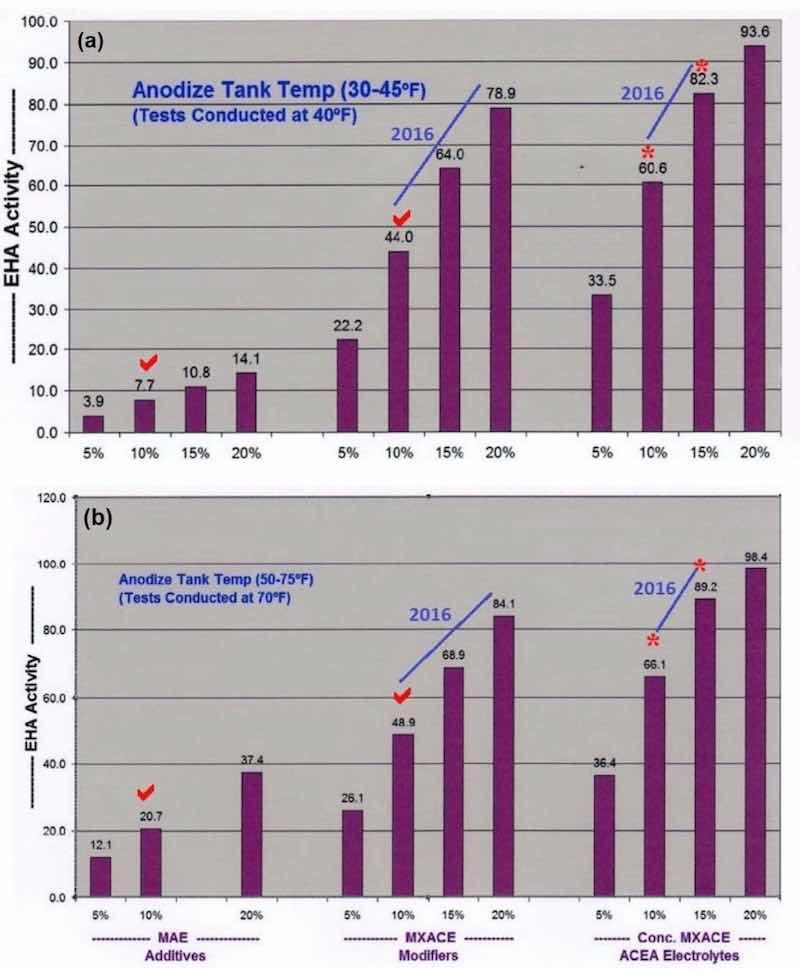
Figure 1- Comparative analysis data on endothermic heat activity at solution temperatures of (a) 40°F and (b) 70°F. The bar graph sets show the effects of increasing concentration of (left) MAE additives, (center) MXACE modifiers and (right) the concentration of MXACE in ACEA electrolytes, illustrating ACXP activation protection in MBO organic electrolytes.
SBCA - TFP (Thin Film Protection) Type II, IIB, 23 and III anodizing
- Sulfuric Acid: 12 - 15 vol%
- ACXP: 5-15vol%
- TXC 361(MBO Electrolyte*): 5 - 7 wt%/vol%
- Temperature: 25 - 35°F/60 - 80°F
- Current Density: 10-60A/ft2 @25-35°F; 10-40A/ft2 @60-80°F
SBCA - HA (Hard Anodize) Type II, 23, II
- Sulfuric Acid: 12-17vol%
- ACXP: 2-5vol%
- TXC 361 (MBO Electrolyte*): 5 - 10 wt%/vol%
- Temperature: 25 - 35°F/60 - 80°F
- Current Density: 10-75A/ft2 @25-30°Fl; 10-50A/ft2 @60-80°F
- *MBO - mixed blended organic (carboxylic acids) electrolyte
A higher concentration of MBO mixed electrolytes and ACXP than what is used for tank operations, must be a major part of all selective brush cell anodizing (SBCA) formulations. Proper coating development is accelerated through increased endothermic heat absorption in the anodic pore structure. Also, ACXP and MBO protects the aluminum and anodic finish at the base of the pore structure throughout the SBCA cycle. In addition, if any masking bleed-out or acid leakage occurs on the bare aluminum, it is protected for a considerable amount of time. This protection can only be realized by using higher concentrations of ACXP. Accelerated complexion endothermic heat absorption, dissipation and added protection within the pore have always been some of our most important contributions to the anodize industry. The bar graphs in Figs. 1a and b, which have appeared in previous papers, represent a comparative analysis of the endothermic heat absorption and protection of ACXP and MBO electrolytes. It is obvious that the heat absorption is far greater than the traditional MAE or other additives. Analytical titration procedures are available with results that can be plotted directly on the bar graphs.
Variable Pulse/Power Package/Data Loggers
Variable slow pulse
Slow pulse is very beneficial for all sulfuric acid and mixed electrolyte (Type II, 23, III) brush anodize processes. However, slow pulse should not be used for Type I or IC anodize. Also, all power supplies/rectifiers used for Type I and IC should be full wave filtered with a maximum of 5% ripple. A quick step ramp procedure (1 volt every 15 seconds) is an excellent ramp choice which we started in 1965 while working with Boeing on BAC 5019. (Please note: BAC originally was misinterpreted with this requirement as "4 volts per minute").
After reviewing past problem-solving situations, we have found the 0.25-0.50 seconds on/off pulse time to be satisfactory. Also, for SBCA we chose to use (5-10%) low pulse for better high current density protection on difficult alloys (2219-7050). Auto- ranging pulse range increases as the voltage and current density increases. However, the high/low pulse range and time can be changed or reset quickly during the SBCA cycle.
Power package/rectifiers
We have six different types of rectifiers set up for selective brush cell anodizing and/or anodic test evaluations cells (ATEC). Three ATEC cells can be connected in parallel so that anodize efficiency can be verified on three different anodize tank samples simultaneously. All six rectifiers, set up to evaluate SBCA wave forms and chemistry, can also be used in production.
- ATS AC/DC secondary SCR Half Wave + APCD; 60-120 VDC, 5 - 10 A (single phase).
- ATS DC Powerstat/Diode Half Wave/Full Wave; 30 VDC, 10 A (single phase).
- BK switch mode (filtered compact); 36 VDC, 10 A
- BK switch mode (filtered); 60 VDC, 5 A
- Digital (filtered test lab); 60 VDC, 5 A
- Extech (filtered test lab); (16 VDC, 5 A) (36 VDC, 5 A)
The choice rectifier (#1 SCR half wave + APCD) is by far the best rectifier for SBCA anodizing, especially difficult alloys.
Anodize is initiated at a very low voltage (1 - 2 V). Rectifier #2 gives fairly good results when it is operated in the half wave mode along with slow pulse.
Switch mode rectifier #3 will give fair results for Type II and 23 anodizing up to 0.5 - 1.5 mils. Switch mode rectifiers should have a pulse unit before attempting to run any 2000 series or other difficult to run alloys. Also, the AXCP and MBO mixed electrolyte concentration can be raised to 10% so that running 2000 series now becomes much easier even at 40 - 50°F while passing Taber abrasion tests per specification requirements.
Data loggers - real time graphic observations
Two different data loggers with 12 channels can be run simultaneously on a laptop so that the brush anodize operator is able to observe the voltage, amperage, current density, amp hours/minutes, temperature and ramp/run cycle, while running the test specimen or part. The data logger with real time graphic observation should be a part of all production SBCA installations, if for no other reason than the Pulse-Step-Ramp cycle fluctuations. There are four-channel portable units available at very affordable prices.
Process Procedure Requirements
This integral part of the complete spectrum is especially important in order to produce quality selective brush cell anodizing (SBCA) on difficult alloys. The following nine requirements have been developed through continual improvements by journeyman anodizers for over 50 years. This problem-solving technology and methodology has been stressed in all of our technical papers. One should study these process procedure requirements (Note: #1 has been modified to 1 - 2 V for selective brush cell anodizing - SBCA).
1. Activation: 1 - 2 V for SBCA/current pulse period
2. Pulse-Step-Ramp/Slow PSR/QSR
3. Auto Ranging Voltage/Current Pulse (high/low pulse increased with mixed organic electrolyte)
4. Dwell Times Increased (2 - 7 min / 3 - 10 mils) (for proper pore structure conditioning)
5. Amperage Decay or Drop Off (ADO)
6. Constant Current Density Ranging (CCDR)
7. Ampere-hours vs. process time (correction factors)
8. Real time graphic observation (monitoring-analysis-reproducibility)
9. Anodic pulse capacitance discharge (APCD)(low voltage-high CD / spikes and deviations)
Data Logger Graphs (DLG)
The ATS real time data loggers represent one of our most important contributions to the anodizing industry. Our new ATS data logger with real time observation was used to run all of the samples for this paper, as shown in the following DLG plots (Figs. 2 thru 11):
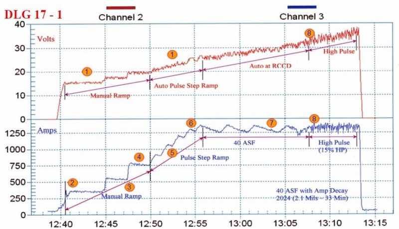
Figure 2 - Anodize training graph (2006 study) for aircraft jet engine parts, showing a 15-min auto-ranging voltage/current pulse step ramp (PSR) to 40 A/ft2 at 38 V; run time of 33 min with a high pulse for the last eight minutes. The dwells during the PSR phase are observed in real time.
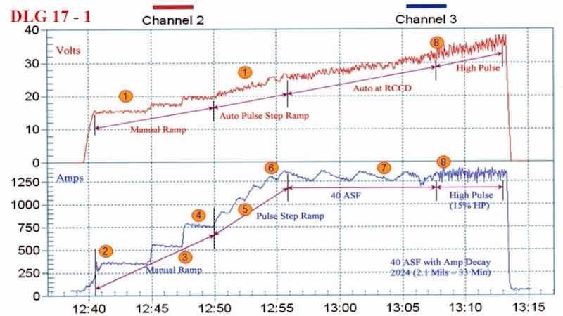
Figure 3 - Data logger graph (2012 study) for anodization of a 2219 alloy (masked mini-test panel), producing a coating of 1.7 - 2.0 mil; showing a 20-min auto-ranging pulse step ramp (PSR) plus anodic pulse capacitance discharge (APCD) to 35 A/ft2 at 14 V; run time of 46 min.
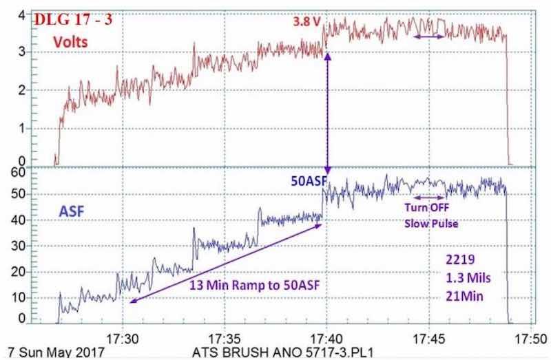
Figure 4 - Data logger graph (2017 study) for hard anodization of a 2219 alloy (masked mini-test panel), producing a coating of 1.3 mils; showing a 13-min pulse step ramp (PSR) to 50 A/ft2 at 3.8 V; run time of 21 min.
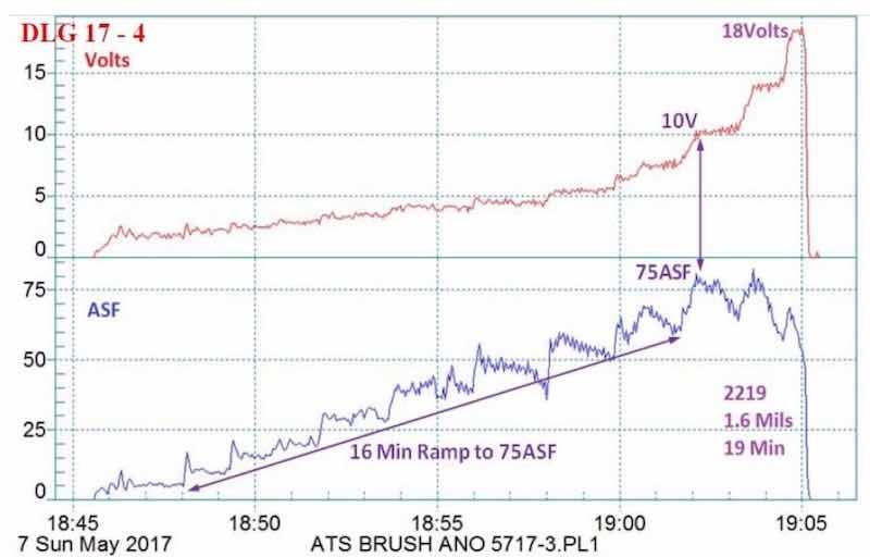
Figure 5 - Data logger graph (2017 study) for hard anodization of a 2219 alloy (masked mini-test panel), producing a coating of 1.6 mils; showing a 16-min pulse step ramp (PSR) to 75 A/ft2 at 18 V; run time of 19 min.
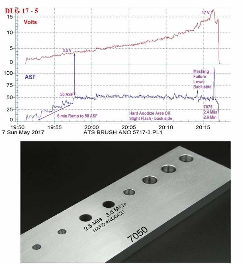
Figure 6 - (a) Data logger graph for hard anodization of a 7075 alloy (masked mini-test panel), producing a coating of 2.4 mils; showing a 6-min pulse step ramp (PSR) to 50 A/ft2 at 18 V; run time of 26 min.; (b) photograph of a 7050 alloy with bore holes selectively processed by this regimen.
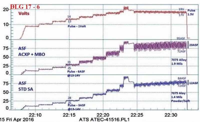
Figure 7 - Data logger graph for anodization of 7075 alloy test panels, using a pulse-step-ramp from 9 to 24 V: Comparison of (blue current density line) a 1.4-mil soft coating formed in a standard sulfuric anodizing bath at 75 A/ft2 with (violet current density line) a 1.9-mil hard compact coating at 85 A/ft2 using an MBO organic electrolyte with AXCP. The electrochemical pulse increased by 150-200% with the latter.
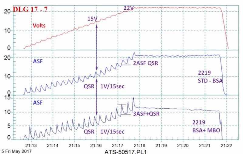
Figure 8 - Data logger graph for anodization of 2129 alloy in a boric-sulfuric anodize bath, using a standard DC power supply and a 4 V/min ramp to 15 - 22V; comparison of (blue current density line) a standard boric-sulfuric anodizing bath (BSA) with (violet current density line) BSA + mixed organic (MBO) electrolyte. The electrochemical pulse increased with the MBO electrolyte.
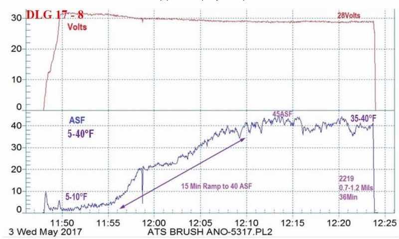
Figure 9 - Example #1 of a data logger graph for anodization of 2129 alloy showing temperature-controlled pore structure development from 5 to 40°F: current density ramp to 45 A/ft2 (15 min to 40 A/ft2), 0.7 - 1.2 mil coating formed at 28V for 36 min.
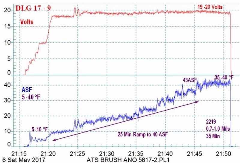
Figure 10 - Example #2 of a data logger graph for anodization of 2129 alloy showing temperature-controlled pore structure development ramped from 5 - 10 to 35 - 40°F: current density ramp to 45 A/ft2 (5 min to 18 - 20 V, 3 A/ft2, 25 min to 40 A/ft2), very hard 0.7 - 1.0-mil anodize coating formed at 20 V for 35 min.
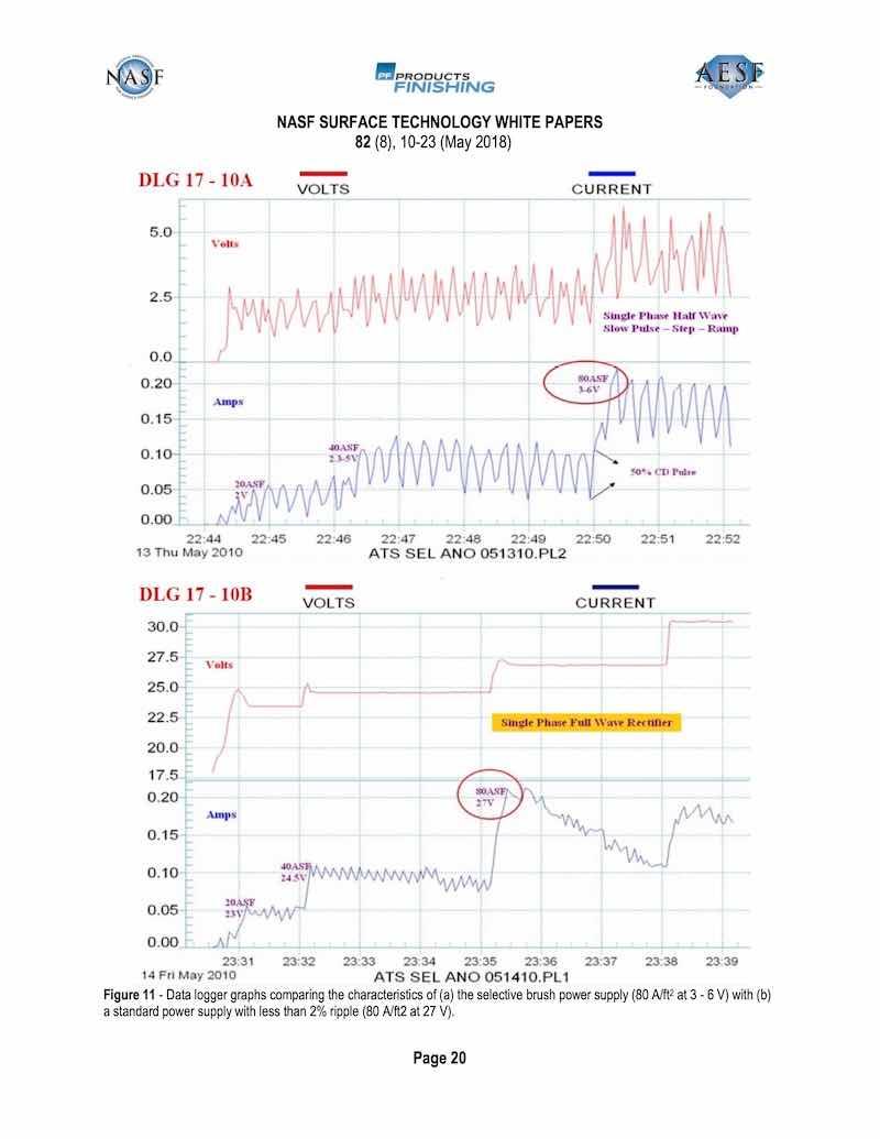
Figure 11 - Data logger graphs comparing the characteristics of (a) the selective brush power supply (80 A/ft2 at 3 - 6 V) with (b) a standard power supply with less than 2% ripple (80 A/ft2 at 27 V).
Photographs / Images
In addition to the selectively anodized bore holes shown earlier in Fig. 6(a), other examples of selective anodization are shown here.
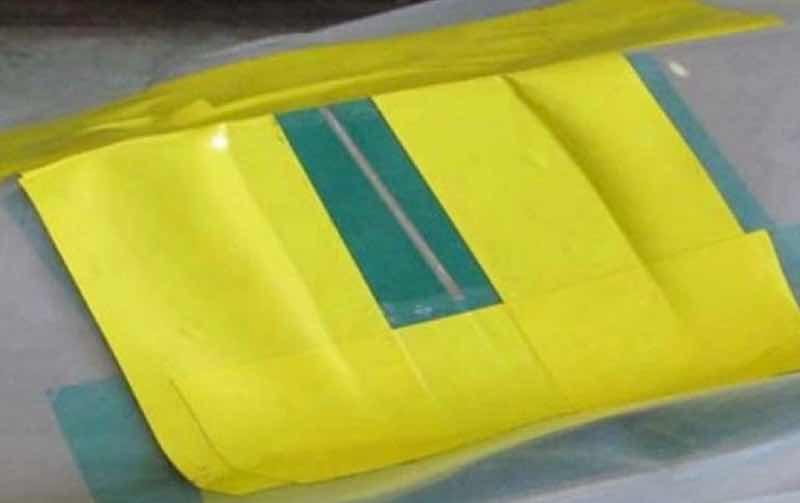
Figure 12- Repair of a severe scratch in a chromic acid anodized coating, showing the finish to be completely blended-in.
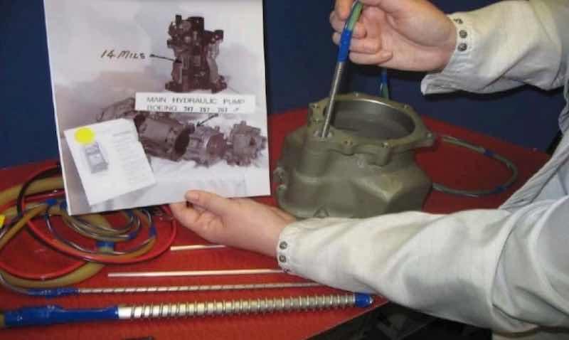
Figure 13 - Hard anodize (8-14 mil) selectively applied in the bore holes of a 356 alloy hydraulic pump.
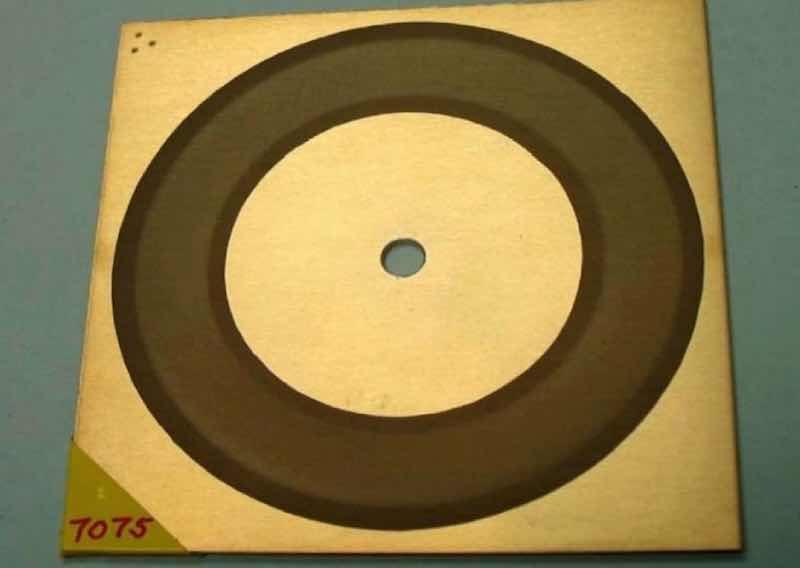
Figure 14 - Taber abrasion testing of a selective brush/cell anodized (SBCA) 7075 alloy.
Conclusions
1. Mixed blend organic (MBO) electrolytes which are formulated with high concentrations of carboxylic, polycarboxylic and hydroxy polycarboxylic acids, should be integrated into all sulfuric acid selective brush/cell anodize (SBCA) processes.
2. MBO electrolytes and/or carboxylic metal complexing agents provide activation at the SBCA probe tip before and during the anodize ramp cycle.
3. MBO and amino polycarboxylic acids (ACXP) provide surface protection against acid attack on difficult alloys (2000-7000 series).
4. Excess heat is absorbed at the SBCA brush probe tip by MBO and ACXP during the initial anodize buildup.
5. Protection is provided near and at the SBCA brush probe tip by MBO and ACXP.
6. MBO electrolytes and/or carboxylic complexing agents protect and accelerate the SBCA anodize growth rate up to 75 A/ft2 on difficult alloys.
7. Secondary SCR half-wave power supplies and anodic pulse capacitance discharge (APCD) produce higher current densities at lower voltages for SBCA anodizing.
8. Data loggers with real time graphic observation should become a part of all SBCA anodizing of difficult alloys. The operator can observe voltage, amperage, current density (A/ft2), amp-hours /minutes, temperature and pulse-step-ramp run cycles.
9. MBO electrolytes and ACXP protect and accelerate throughout the complete anodize SBCA process.
References
1. D.C. Working, U.S. Patent 3,343,943 (1969)
2. F.C. Schaedel, U.S. Patent 3,418,222 (1968)
3. F.C. Schaedel, U.S. Patent 4,152,221 (1979)
4. P. Kljucaricek, et al., U.S. Patent 4,879,018 (1989)
5. F.C. Schaedel, “Pulse Ramp Mixed Electrolyte Anodizing Automated & Practical - All Aluminum and Titanium Alloys,” Proc. AESF/SFIC SUR/FIN 2005, St. Louis, Missouri, pp. 267-278 (2005).
6. F.C. Schaedel, “The Complete Spectrum Guide to Top Quality Anodizing: Maximizing Efficiency and Energy Savings,” Proc. SFIC SUR/FIN 2006, Milwaukee, Wisconsin, pp. 168-187 (2006); also Plating & Surface Finishing, 93 (12), 38-44 (2006).
7. A.D. Juhl, K. Burfelt and P. Weldingh, “Slowing the Pulse, Products Finishing, 72 (6), 34-37 (2008).
8. F.C. Schaedel, “New Energy Saving Electropolish/Anodize Process Produces ‘Type 23’ Heavy Thickness and Salvage Hard Anodize for Discrepant/Worn Part Repair,” Proc. SFIC SUR/FIN 2009, Louisville, Kentucky, Presentation: Session 4, June 16, 2009.
9. F.C. Schaedel, “The Leading Edge Guide to Top Quality Anodizing Using the Complete Spectrum Approach with One Universal Type I - II - III - (123) Mixed Electrolyte,” Proc. NASF SUR/FIN 2011, Rosemont, Illinois, Presentation: Session 10, June 14, 2011; Summary: Products Finishing - NASF Report, 76 (9), 14 (2012); Full Paper: Products Finishing, http://short.pfonline.com/NASF12Jun1, (2012).
10. F.C. Schaedel, “New and Unique Variable Pulse Ramp Technology for Maximizing Pore Structure Conditioning in Type IC, II, III and 123 Anodize with Greater Efficiency and Energy Savings,” Proc. NASF SUR/FIN 2012, Las Vegas, Nevada, Presentation: Session 2, June 12, 2012.
11. F.C. Schaedel, “Aerospace Anodizing in a Non-Chrome World,” Proc. AAC Conference, 2013.
12. J. Runge, “Interfacial Phenomena in 7000 Series Alloys and Their Impact on the Anodic Oxide,” Proc. AAC Conference 2013.
13. F.C. Schaedel, “Unique New Thin Film Anodize Technology for Superior Adhesion Promotion, Bonding and Microfinish using One Universal Electrolyte with Type IC, IIB and III Capabilities,” Proc. NASF SUR/FIN 2014, Cleveland, Ohio, Presentation: Session 1, June 9, 2014.
14. F.C. Schaedel, “Optimizing Non-Chrome Anodize Processing Solutions with New Amino Complex Ion Protective Chemistry Using the Complete Spectrum Approach,” Proc. NASF SUR/FIN 2015, Rosemont, Illinois, Presentation: Session 3, June 9, 2015.
15. F.C. Schaedel, “Sulfuric / Organic Electrolytes and Total Quality Improvement (TQI) for Present / Future Anodizing Requirements,” Proc. NASF SUR/FIN 2016, Las Vegas, Nevada, Presentation: Session 12, June 8, 2016; Summary: Products Finishing - NASF Report, 81 (10), 14 (2017); Full Paper: Products Finishing, http://short.pfonline.com/NASF17Jul1, (2017).
Fred Charles Schaedel is President of Alpha Process Systems in Westminster, California. Visit http://www.alphaprocess.com. He started Anodizing and Plating at Hudson Plating Works and Harshaw Chem. Co. in Cleveland, Ohio, in 1957. He has developed specialized anodize additive modifiers, and pulse ramp systems — including waveform technology — and established training programs in the anodizing industry dating back to 1962.