A 6 VDC tank-voltage difference was observed when comparing the steady-current-at-steady-voltage behavior in two anodizing processes under identical conditions.
 Dr. Moisey LernerOne is a conventional straight DC process; the other uses DC and AC supplied by a “resonant” power source. It is suggested that the 6V overvoltage at straight DC creates arcing in a layer of free molecular oxygen at the bottom of each pore in the oxide film. An arc generates oxygen plasma with constant conductivity, allowing the direct current to flow steadily. Plasma is considered a major factor in the lower quality of oxide films formed by straight DC compared to the arc-free coatings formed by DC + AC.
Conventional straight DC anodizing of aluminum alloys is ordinarily conducted at a current density of 1.5 A/dm2, forming a 0.5 mm coating/min (about 25 mm/hr), in a water solution of 170 g/L sulfuric acid at room temperature. Remarkably, 1.5 A/dm2 flows steadily (without drooping) only after a specific level of tank voltage is reached. This level ranges from 17 to 20 VDC, depending on the composition of the aluminum alloy, the age of the electrolyte, and deviations of electrolyte temperature. For any other current density, there exists a corresponding specific DC voltage at which this current is kept steady (see Fig. 1). In the straight DC process, the steady-current-at-steady-voltage phenomenon is peculiar only for room temperature anodizing.
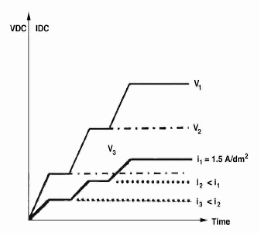 Fig. 1—Three levels (v1 > v2 > v3) of straight-DC tank voltage to establish steady current densities, i1 > i2 > i3.Straight DC hard coating is conducted at electrolyte temperatures close to 0°C. Current density is at least twice that of conventional anodizing. An oxide film forms at a rate of 1 mm/min or more. The steady-current-at-steady-voltage phenomenon is foreign to straight DC hard-coating; however, the tank voltage must increase to maintain a steady hard-coating current. It may be asked how the steady-current-at-steady-voltage phenomenon is achieved in straight DC anodizing at room temperature. This question can be quantified by considering another type of anodizing.
Originally published in May 1998.
DC + AC Anodizing
A sinusoidal AC voltage at industrial frequency (50 or 60 Hz) is superimposed on the DC voltage component across the tank using a “resonant” power supply.1 The amplitude of the AC component should be below or equal to that of the DC component. A steady current density of 1.5 ADC/dm2 is reached at a certain level of the DC + AC tank voltage. The DC component of this voltage is about 6 V lower than the tank voltage in straight DC anodizing under equal conditions. Another difference: in the DC + AC process, the steady-current-at-steady-voltage phenomenon can be observed at a wide range of electrolyte temperatures. In the straight DC process, at room temperature only.
The question above can be narrowed to: “Why is the overvoltage by 6 V required for initiating steady current at steady voltage in straight DC conventional anodizing?”
Breakdown Hypothesis
It is suggested that the 6 V overvoltage in the straight DC process is needed to initiate breakdown in the oxygen-gas layer at the bottom of oxide film pores (see Fig. 2). As is known, generating free oxygen on the anode and free hydrogen on the cathode (called “polarization of electrodes”) is an inevitable companion of the straight DC anodizing process. For breakdown, about 1 million volts are needed to initiate it in a 1-centimeter-thick layer of gas at normal atmospheric pressure. Six VDC will proportionally initiate a breakdown in a layer of oxygen, the thickness of which does not exceed 6 VDC/1,000,000 VDC/cm, or 0.06 mm.
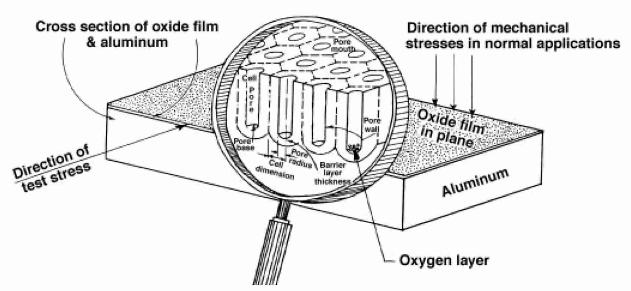 Fig. 2—Pore structure of oxide films anodized on aluminum in water solutions of strong acids (sulfuric, oxalic, etc.).
On the other hand, according to Faraday’s Law, the higher the DC through the tank, the thicker the oxygen layer (it should be recalled that only a small portion of the total current generates free oxygen; the majority forms the oxide film by chemically combining with aluminum). If a layer exceeds 0.06 mm, no breakdown occurs. The layer resistance increases, reducing the current. The layer becomes thinner. Once 0.06 mm is reached, breakdown is initiated. As a result of the breakdown, a poorly conductive layer of free oxygen is transformed into plasma with much higher conductivity, which remains constant. Plasma maintains a steady current flow despite increasing film thickness. Every DC voltage level (above 6 VDC) has a specific current density that remains steady due to plasma. Plasma is an aggressive environment affecting the pore wall material. Plasma makes walls more susceptible to contamination by crystallized water and sulfates. Several scientists have thoroughly described this contamination. Figure 3 illustrates pore contamination according to Thompson and Wood.2
Assertions
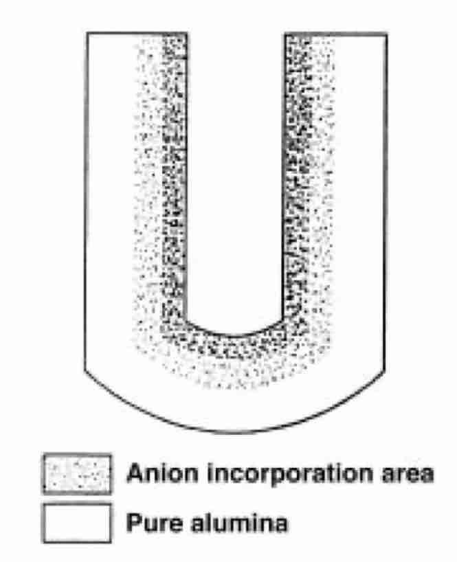 Fig. 3—Contamination of pores during anodizing.Pore walls, initially composed of pure, hard Al2O3, are transformed into a gel-like substance composed of aluminum hydroxides and aluminum sulfates, which cause the walls to swell.
- Corollary 1. As pore walls swell, the pore volume decreases.
- Corollary 2. The process of pore-wall transformation intensifies (a) especially in the presence of oxygen plasma, which needs 6 VDC overvoltage to be created, and, to a lesser degree, (b) by the increase of electrolyte temperature, and (c) by the increase of sulfuric acid concentration.
In the DC + AC process, there is no plasma and no (or very little) free oxygen in the pores. The steady-current-at-steady-voltage phenomenon is observed at lower (6 VDC) levels than in the straight DC process.
Experimental Justification
Of the Breakdown Hypothesis, Soft and Hard Coatings with Straight DC: We differentiate between conventional anodizing processes at room temperature (which form soft coatings) and hard-coating processes at temperatures close to 0°C (which form oxide films with substantially higher abrasion resistance). The breakdown hypothesis explains this difference:
Soft coatings: At room temperature, with the electrolyte, the plasma-induced destruction of pore walls is significant—pure Al2O3 is extensively replaced by aluminum hydroxides and aluminum sulfates, making the coatings soft.
Hard coatings: At lower temperatures, wall destruction is reduced, and coatings become much harder. Film resistance substantially increases during the process, however, because the number of pores in the film declines as the tank voltage increases. As a result, the DC tank voltages for hard-coating become several times higher than for the conventional DC process. The energy required to form the film and chill the electrolyte increases proportionately. The straight DC hard-coating process becomes many times more expensive.
With DC + AC: There is no differentiation between soft anodizing and hard anodizing in the DC+sinusoidal-AC processes.36 The tank voltage is 6 V lower than in straight DC, and no arc is created at the bottom of the pores. The arc-free coatings are incomparably less susceptible to the influence of electrolyte temperatures because the plasma-activated destruction of pore walls is not present.
Reducing electrolyte temperature will not result in a dramatic increase in tank voltage, as observed in straight DC processes. The DC voltage component of a DC + AC tank will increase by 1 V if the temperature drops, staying well below 20 VDC, even at coating rates 3 times faster (1.5 mm/min) than in conventional anodizing.
Limit of anodizing rate with straight DC: The rate of soft anodizing is limited to about 0.5 mm/min (25 mm/hr). Higher rates, which demand current densities exceeding 1.5 A/dm2, will cause catastrophic dissolution of aluminum parts, called burning, because the heat released in the oxide film exceeds safe levels. In conventional anodizing, the energy level is safe if it is close to
1.5 A/dm2 x 20 VDC = 30 W/dm2
Should the 1.5 A/dm2 double and the tank voltage increase to 25 VDC (at least), heat generation then grows to a level of 75 W/dm2, or 2.5 times the safe level. In DC hardcoating, the average current density during a run is rarely much higher than 3 A/dm2, and forms 50 mm of oxide per hr.
With DC + AC: The rate of arc-free DC + AC anodizing at room temperature can safely be increased to twice that of conventional anodizing, without the danger of burning. Indeed, if the current density is 3 A/dm2, and the tank DC voltage component is 11 VDC, the energy released in the coating is only 33 W/dm2, which is very close to the safe level, and no burning occurs. At lower electrolyte temperatures, average current densities can be easily raised to 4.5 A/dm2, and even 6 A/dm2, with no danger of burning.
Limit on sulfuric acid concentration with straight DC: A water solution containing 170 g/L sulfuric acid is the electrolyte concentration commonly used in conventional anodizing. Higher sulfuric acid concentrations, such as 300 g/L, are used for certain hardcoating processes but not in conventional anodizing. A concentration of 300 g/L is more desirable because the electrolyte has better throwing power and, most importantly, reduces tank voltage, resulting in lower power consumption. On the other hand, the higher the sulfuric acid concentration, the more aggressively it attacks pore walls, especially in the presence of plasma. A coating produced by straight DC at 300 g/L at room temperature therefore offered half the abrasion resistance obtained with 170 g/L. In hardcoating, lower electrolyte temperatures reduce the aggressiveness of the sulfuric acid. Thus, using 300 g/L is allowable if a run does not last more than 90 min; otherwise, return to 170200 g/L is recommended.
With DC + AC: In the arc-free DC + AC process, the higher concentration of electrolyte is harmless. At 300 g/L, the tank DC voltage component drops below 10 V at 1.5 A/dm2. This makes the DC + AC process even more attractive for architectural anodizing, with more savings on electric bills. Lower tank voltages have still another advantage. As mentioned above, the number of pores declines as the tank voltage increases and, conversely, increases as the tank voltage decreases.
This means
- that the DC+AC films are more porous, having more room for coloring agents in two-step architectural anodizing
- A DC + AC coating is thicker than the straight DC coating produced by the same amount of electricity (Ampsec)
Savings from using the DC + AC process, therefore, increase. DC + AC coatings require less electricity to produce the same thickness as the straight DC process. An additional 20% of electricity can be saved.
Limit on process interruptions with straight DC: It is well known that a long interruption should be avoided between the first (anodizing) step and the second (electrolytic tin-coloring) step of architectural anodizing. If the coating dries, the quality of the coating is impaired. It is consistent with the breakdown hypothesis. If gel-like walls of pores are produced in the plasma environment, drying would irreversibly affect the ability to accept tin cations uniformly.
With DC + AC: The arc-free DC + AC coatings are insensitive to drying. A coating formed at the first step, under equal conditions with the straight DC process, can be thoroughly dried and kept for hours before the second step. The quality of the tin coating will not be impaired after this interruption. It is a spectacular proof of the breakdown hypothesis for the straight DC process.
Dulling colors of thicker coatings with straight DC: It is well known that the brightest and best reproducible colors in the two-step-straight DC process are obtained if the coating thickness is in the range of 6 to 10 μmm. A thicker coating, even a 12 mm coating, is not as deep in color as a 6 mm coating. This challenges common sense. It is logical to expect that thicker coatings have more room in their pores for more coloring agents to accept, but it is not so for the straight DC process. The plasma hypothesis easily explains this paradoxical phenomenon. Thicker coatings are processed in the electrolyte longer and are affected longer by the destructive effect of plasma. Pore walls swell and, therefore, steal space from coloring agents. That is why coatings thicker than 10 μm are not as intense in color.
With DC + AC: The arc-free DC + AC coatings behave according to common sense: the 12 mm coatings have the same or more intense colors than 6 mm coatings under equal conditions. This is another significant confirmation of the breakdown hypothesis.
Conclusions
1. There is no technical or economic sense in using straight DC in two-step architectural anodizing because “resonant” power supplies1 for the arc-free DC + AC process are available. On a more modest scale (up to 5,000 ADC), similar power supplies have been successfully used for low-voltage industrial hard-coating during the last 20 years.
2. The arc-free DC + AC coatings are less expensive to produce, are harder, provide brighter colors, and are more resilient with technological variations.
Acknowledgments: The author wishes to express gratitude to Roger Huebsch, president of Sanford Process Corp., who inspired, sponsored, and managed the two-decade research and industrial implementation that culminated in the arc-free anodizing concept and technology. I am also thankful to Leonid Lerner, Valery Sukonnik, Marie Polomares, Anthony Ita, and many others for enlightening discussions.
Dr. Moisey Lerner was a physicist with the Tomin Corp., in Wellesley, MA 02181-0015. He earned a PhD in electrical engineering for three-phase-AC barrier-layer-anodizing of pure aluminum for electrolytic capacitors, widely implemented in the former Soviet Union industry. In 1975, he invented a “resonant” DC + AC power supply and processes, reducing to 15-20 VDC the tank voltages for hard-coating aluminum alloys. Beginning in 1992, he has concentrated on two-step architectural anodizing, inventing a modification of the “resonant” power source for supplying tens of kilo-amperes to an anodizing tank.