This paper will explain some insights and actions that will help you maintain a top-performing Ultrafilter System, extend the life of your UF Elements and gain more permeate.
You will better understand the mechanics of UF membrane, gain insight on operational concerns, think about some root causes, and consider some best practices with UF System design and operation.
For consistency, this paper focuses on spiral UF elements, which are the most common type used in E-coat paint systems. Tube, hollow fiber, flat sheet, and ceramic geometries will not be discussed.
UF Membrane Mechanics
Ultrafiltration (UF) membrane is manufactured by coating one side of a paper-thin, nonwoven substrate with a thin polymer layer. The polymer side is shiny and is where the paint makes contact with the filter. The other side is the permeate side, which is where water and other low molecular weight components (aka waters) appear after they pass through the small pores of the polymer layer. Once wound with a spacer sheet into an element, the polymer layer is fixed in place and protected by other layers to make it robust.
Many filters (such as air filters) are considered ‘depth filters’ because they work by forcing the desired material through the filter. Because they capture the harmful particles, these filters must be changed when they become full and cannot function any longer.
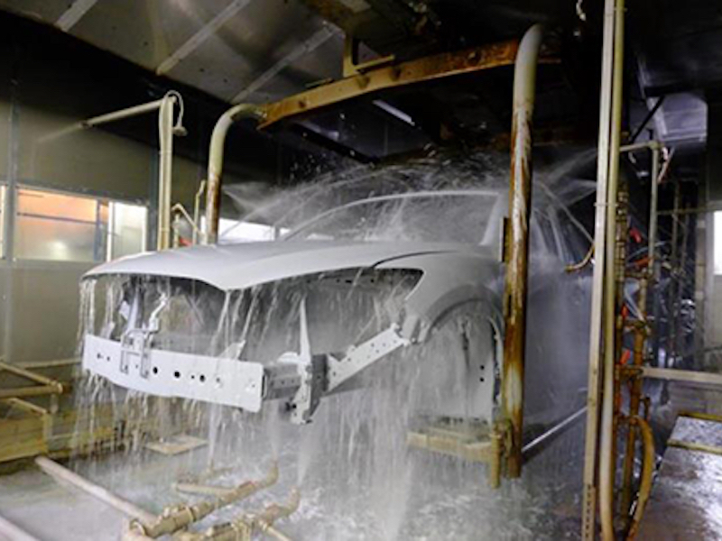
UF membrane is not this type of filter as it works on a cross-flow principle. The desired waters transfer through the filter as the solution (e-coat paint) passes across the top layer. E-Coat paint is returned to the paint bath and permeate is diverted for use elsewhere.
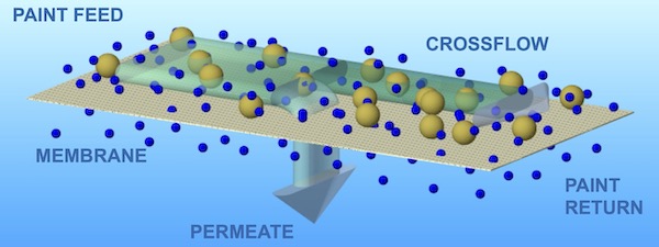 Figure 1
Of note is a gel layer that forms on the polymer face as paint begins to flow across it. Waters can pass though small pores in the polymer. Some of the larger components in the paint are pulled over toward these pores but are unable to pass though. At this point the ‘too large to pass through’ components have lost their velocity and find it hard to move out of the way. In a sense, they become ‘double parked’ on the face of the polymer. If there are just a couple of double parkers, the waters can still pass through. When the gel layer gets thick and viscous, the waters are greatly restricted from passing through and permeate production is much, much lower.
Operational Concerns
Over time, UF elements will produce less permeate. Low permeate flow is by far the most common complaint received from UF end-users. Permeate is molecular material separated from paint solids because it can pass through a UF membrane’s small pores. A ‘7640 type’ UF element might have 4.5 gpm (17 lpm) of permeate when new. Most end users consider permeate flow below 1 gpm (~4 lpm) to be too low and a signal that it is time to install a new UF element.
Beyond the normal aging process, events can occur that cause reductions in permeate output. These are addressed in this section.
Low Paint Flow
Low paint flow results in less active force that is needed to press the waters through the small pores of the UF membrane. Also, low paint flow generates less turbulence on the face of the membrane, which allows the gel layer to grow. Low paint flow is the primary root cause in a majority of cases where the UF permeate is low or the element experiences short life.
In Figure 2a and 2b on the next page, large particles can be seen on the inlet face of the UF element. The particles are impeding the flow of paint. The result will be a loss of permeate flow and short life of the UF element. Proper pre-filtering will prevent this from happening.
Also, in Figure 2b, the blocked inlet face has allowed the paint flow to make a new path by separating several leaves to make a larger opening for the paint to flow. This changes the orientation of the leaves and can result in a tear of the membrane, which will result in a leak.
 Figure 2a and 2b
Leaking UF Membrane (paint in the permeate)
Most UF element manufacturers perform a bubble test to ensure there are no leaks. Although leaks after startup are uncommon, they can occur. For example, if the UF paint feed pump stops for some reason (power outage, maintenance work, etc.) it will need to be re-started. It is critical that the pump NOT be allowed to reach full rpm’s right after the pump motor is re-started. If this occurs, a ‘tsunami’ of paint inside the piping will expel air at a very high rate of speed and may cause damage to the UF Elements and the piping. (Figure 3 is a photo of telescoped element.)
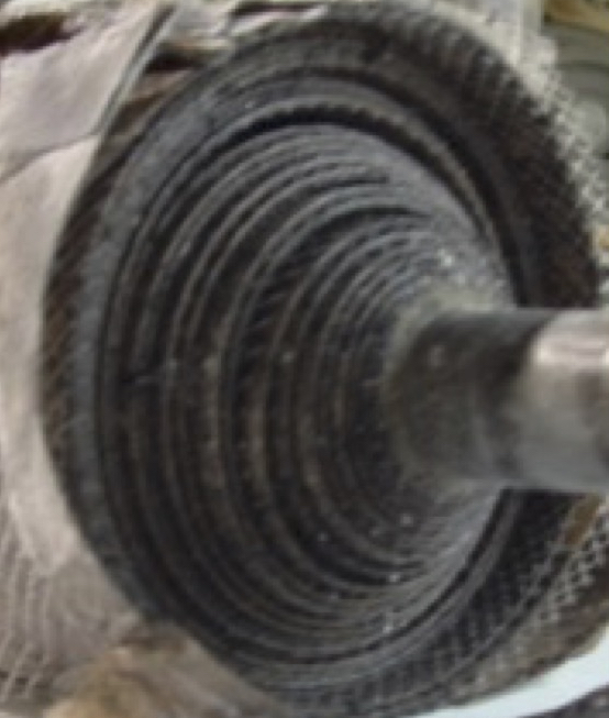 Figure 3A ‘Soft Start’ is an electrical device than can be set to allow 45 to 60 seconds to run the pump up to its full speed, or is there is no soft start, the operator has to take 60 seconds to fully open the UF system inlet valve. Similarly, a VFD can be set up to safely ramp up the UF feed pump’s speed to avoid damage.
Leaking UF membrane can also result from excessive permeate pressure that creates a separation between the membrane and the polymer layer. Excessive pressure in permeate outflows can be cause by too-small manifolds, throttled valves or obstructions to permeate flow.
Foam
If foam forms on the surface of the E-coat bath, it (or its smaller components) will eventually pass through the pump and into the UF system. The foam components are small and go through a 25-micron rated filter bag. The portion of the foam bubble exposed to air will become ‘air dried’ to some extent and will not pass through the UF membrane pores. Instead, it may linger on the surface of the UF membrane acting as a barrier, much like placing plastic wrap over the holes of a colander.
Air Bubbles In The Permeate Flow Meter
Entrained air in paint can cause issues similar to what occurs with foam. Entrained air can partially cure paint that it comes into contact with. This air-bubble particle then may linger on the gel layer, making it harder and thicker, and more difficult for waters to pass through. Make sure there are no paint pump suction pipe leaks that could allow unwanted air to mix with the paint.
Root Causes
In addressing operational issues, it is important to seek out the root cause and repair or replace, as necessary. Below are some examples of items that may be at the core of operational issues that are presenting themselves.
Broken Fiberglass Housing
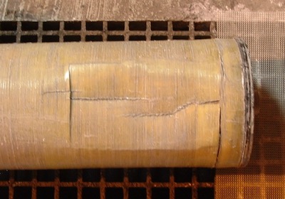 Figure 4Most spiral UF elements have a thin layer of fiberglass wound over the OD of the UF membrane spiral assembly. This is meant to protect during shipping and handling. On occasion, an end-user has reported that the fiberglass has broken. Inspection showed the fiberglass to be cracked, with pieces pointing inward (i.e. imploded). Figure 4 on the next page shows an imploded fiberglass housing.
When this occurs, usually the UF membrane is torn and paint will be visible in the permeate flow meter. The UF element will need to be replaced.
Missing/misplaced Valve Handles
UF systems have multiple valves. For example, a UF system with four UF elements can have as many as twelve different valves. The valve handles can fall off and in some cases are not put back on properly. A valve handle installed backwards or reversed may cause system damage and element failure.
“Plan the work. Work the plan.”
For proper operation of your UF system, a checklist should be required for each different task an operator is expected to perform, especially if the operator is inexperienced. When it is necessary to change a UF element, change a pre-filter, bring a new UF on line, or restart the UF system after a power outage, written instructions are key to informing staff of the proper way to perform each task.
Some examples include:
- The inlet valve to the UF system should never be throttled – it needs to remain fully open. Only the UF system outlet valve should be throttled to achieve the proper flow of paint.
- If there is no Soft Start or VFD on the UF feed pump, on start-up the operator must manually open the valve to the UF system taking a full 60 seconds to slowly open the valve and avoid damage to equipment.
- Each valve needs its own valve tag that is referenced by a checklist. The valve should have a valve ID number and a color code: red = normally closed, green = normally open, or white = normally throttled.
New employees need training and orientation in the operation of the UF system. Many vendors (UF Element/UF Machine/E-coat paint/System Designer) provide training materials and assistance creating, updating and maintaining the UF Operator’s Manual and checklists. Daily log sheets are critical to understanding trends over time and should be part of all operator’s daily work schedules.
Prefilter
When compared to other geometries, a drawback of spiral wound UF elements is the need to pre-filter incoming e-coat paint to keep large particles from blocking narrow paint flow channels. The most popular type of prefilter is a #2 filter bag with a plastic collar. Not recommended is a steel ring bag filter that may allow some paint to bypass and enter the UF element, where large particles can block the flow of paint and lead to permeate flow reduction.
25 micron rated bags are appropriate for a majority of E-coat end-users and approved by most paint companies. Check with your paint supplier if you are considering using a smaller micron size.
Cleaning and the Gel Layer
As discussed in the membrane design portion, a gel layer forms on the polymer face of the membrane as paint begins to flow across it. It may be possible to perform a chemical cleaning. However, experience has shown it is very difficult to recover once the gel layer has become thick and viscous. Relief from cleaning typically does not last long…here is why: The surface area of the 7640 UF element is almost 30 m2 (~300 SF). During a cleaning operation, the easiest to reach portions are cleaned first. Once an opening in the gel layer has been made, much of the cleaning solution will pass though this opening – leaving a lot of the remaining 30 m2 uncleaned. When paint is brought back after a cleaning, the initial permeate rate is improved, but it will quickly fall as cleaned sections once again form a new gel layer.
Avoiding Potential Problems: Prevention and Planning are Key
This section includes some tips we’ve learned along the way.
Fear the ‘shear’: Select a UF feed pump with less than 12” diameter impeller. This ensures the impeller tip speed does not exceed 30 m/second (100 Ft/second), which can be quite extreme. The high velocity can tear paint molecules apart. The smaller torn pieces will attempt to move through the UF membrane pores. Because they are too large to pass, the torn pieces will block many pores and reduce permeate flow.
Know your paint flow: 85 gpm per 7640 Element at 3.75 Bar (55 psi) inlet pressure is the recommended operating conditions for one 7640 type UF Element. Install a magnetic flow meter or pump volute mounted pressure gauge on your system. Proper paint flow is the key for proper operation and long life of the UF Element. A paint flow meter will pay for itself as you will have knowledge that the required flow is passing through the UF System.
Make sure paint is well-mixed: Place UF feed pump suction on opposite end from replenishment paint feed exit to bath. Keep replenishment paint away from the UF feed pump inlet until it becomes extremely well mixed with the existing paint in the E-coat paint bath.
Double up: Be sure to use double mechanical pump seals, recommended for horizontal type centrifugal pumps. Permeate can be used to flood the space between the two seals.
Filtering fundamentals: A #2 size 25-micron, glazed filter bag with a plastic collar is recommended for most E-coat operations – confirm with your paint supplier. The plastic collar will ensure there is no bypass around the bag filter. Filter bags must have a glazing or heat treat on their exterior surface to fuse together all fibers. The use of non-glazed UF bags will quickly lower UF permeate output.
- While a pre-filter is being changed, the UF system still needs a full flow of paint to operate. The addition of an extra bag filter vessel or a filter vessel pot is recommended.
- Limit flow to no more than 105 gpm per #2 bag vessel. If flow is too high, it is possible to damage the seams of the pre-filter bag and allow unfiltered paint to enter the UF element.
Paint feed velocity: Keep paint feed velocity between 2.5 to 3.5 m/second (8 to 12 Ft/second) by tapering the manifold pipe diameter as needed. The largest diameter will be at the start and the smallest diameter at the end for the last UF Element.
- If velocity is slower than 2.5 m/second (8 Ft/second), paint solids will tend to fall out of solution. Faster than 3.5 m/second (12 Ft/second), and the pressure drop really gets to be significant.
- Do not use any dead ends, always use a long sweep elbow for last UF element. Dead ends create a low velocity zone where paint solids will fall out of solution.
- Make sure to provide 85 gpm paint flow per 7640 UF element.
- Maintain 1 Bar (15 psi) paint outlet manifold pressure. A driving force is needed at the exit end of the UF element to encourage waters to pass through the small pores on the exit side of the UF element. You want all 30 m^2 (300 SF) of UF membrane working as long as possible.
System design essentials: Make sure there is a bored inside diameter surface in the PVC UF housing. PVC pipe is not truly round. There is a spec for ‘Out of Round’, so the PVC UF Housing ID must be bored to ensure it is round. The cup seal on the inflow end of the UF element will stop paint from bypassing around it.
- Permeate manifold needs a pressure gauge that limits pressure to 1/3 Bar (5 psi). A UF system must have a pressure gauge on the permeate manifold. This will protect the fragile polymer from being damaged. The pressure on the polymer side ALWAYS has to be higher than the substrate side – or else the polymer will be torn or ripped open and a paint leak will occur.
- All manifolds require bottom drains. At some point the system will be stopped for maintenance and a method to remove all paint solids is needed
- Install a drip pan under the UF skid. This will collect some paint leaks or drips that are bound to happen over the life of the equipment.
- Build your system with calibrated, mineral-oil filled, 10 cm (4”) diameter pressure gauges with guards. It is important to trust your UF system pressure gauges. Have them calibrated on a regular basis.
- System designers are required to provide a by-pass but often cut corners, which impacts everyday operation. When the bypass valve on the UF machine is closed, a dead end is created. While cracking open the valve will allow some solids to escape, it will create high pressure on the return side of the system. To avoid dead end situations, paint by-pass lines NEED to go to back to the E-coat bath.
- Include a DI water system to manually flush UF elements as needed. A UF element is typically water-tested before it is shipped. The element is then packed in a preservative that needs to be rinsed out before it is operated on paint. DI water can be used to rinse out the preservatives to the waste water system.
Maintenance tips: Change bag filters with ½ Bar (7 psi) max increase. It is best practice to change bag filters once a certain pressure differential (Inlet Pressure – Outlet pressure) is reached.
- Do not close or throttle permeate. A general rule is to never close a permeate outlet valve, unless the flow of paint to the UF element has been stopped. A corollary rule is to never touch the permeate outlet valve. Restricting permeate flow in and of itself is not necessarily harmful to the UF element; however, turning off completely in error will lead to problems.
- Make sure cup seals are correctly placed. When installing new UF Elements be sure the cup seals will ‘inflate’ and stop any paint from escaping past them.
- Locate your pump curve and keep with your Operating Manual for reference.
- Service UF feed pumps every year. Inspect pumps once a year to make sure they have the proper impeller clearances and are operating in an efficient manner.
- Keep proper paint flow & 1 Bar (15 psi) outlet pressure. The most important daily checks are: 1) Do I have the proper paint flow? 2) Is the paint outlet manifold pressure 1 Bar (15 psi)?
- Replace all UF elements at the same time. It is not good practice to change just one UF Element at a time, since this will lead to an unbalanced hydraulic condition. The new UF Element will take more paint flow (it has less resistance) and the older elements will have less paint flow/less permeate. Purchase UF Elements over a period of months and keep them in stock so all the UF Elements can be changed at one time.
- Aim to keep steady for 12 months and do no chemical cleaning. If the incoming paint flow rate is kept at the proper level & the pre-filtration system removes large particles from entering the UF element, the result should be a year of trouble-free operation. In addition, it is possible not to have to perform any chemical cleaning during this time period.
Frederick Hess is CEO and Chief Engineer at UFS Corporation. Please visit https://www.ufsc.com