Composite materials have been widely used in the aviation field due to their high specific strength, large specific modulus, strong designability, good fatigue resistance, superior corrosion resistance, and ease of overall formation.
The use of composite materials in the aircraft structure design can not only effectively reduce the weight of the aircraft, greatly improve the flight quality and performance of the aircraft, but also increase the service life of the aircraft structure and reduce the maintenance cost of the aircraft, which has considerable economic benefits. Therefore, the amount of composite materials used on the aircraft and where the composite materials are applied have now become one of the important indicators to measure the advancement of aircraft structures.1-4
The new type of aviation aircraft uses a large number of composite materials to improve the performance of the entire aircraft by taking advantage of its high strength and light weight. But at the same time, the poor electrical conductivity of composite materials (compared to metal materials) is also revealed. During the flight, a large amount of static charge is generated on the surface of the composite material. The static charges that are not released in time accumulate on the surface of the aircraft, and they are easily struck by lightning. This brings serious hidden dangers to the reliability and safety of the aircraft. Therefore, it is necessary to metalize the surface of the composite material to achieve conductivity, lightning protection, and electromagnetic shielding performance.5-7 At this stage, the commonly used resin-based composite material metallization methods include electroless plating, electric brush plating, vacuum evaporation, magnetron sputtering, cold spraying, and thermal spraying, etc. Among these, more and more attention has been paid to thermal spraying technology because of its low cost, flexible operation, high degree of automation, not limited by the size of the workpiece, easy on-site construction and maintenance, easy to master, and relatively less environmental pollution than other methods.8-15 The sprayed aluminum coating on the surface of the composite material has been applied to conduct electricity and lightning protection on the leading edges and ends of the wings and the outer surface of the fairing of Boeing aircraft.16
Important Technology in Surface Engineering
Thermal spraying is an important technology in the field of surface engineering. Firstly, the sprayed material is heated to reach a molten or semi-melted state, and then sprayed and deposited on the pretreated surface at a certain rate through a specific device to generate a certain thickness of coating. Sun et al.17 studied spraying Al and A12O3 coatings on resin matrix by gas plasma spraying to improve the mechanical properties of resin surface. The effects of spraying current and spraying distance on phase composition, microstructure and mechanical properties were also investigated, and the bond strength of the coatings was measured. The results show that the spraying parameters have a significant effect on the phase composition, microstructure and mechanical properties. The maximum coating adhesion obtained in the test is 5.21 MPa. At this time, the current force is 180A and the spraying distance force is 190 mm. Wang et al.18 studied the effect of arc spraying energy on the microstructure and mechanical properties of Zn-Al coating of epoxy resin matrix composites. The tensile strength of the coating was measured by RGD-5. The microstructure of the coating was observed by SEM and the phase composition of the coating was measured by XRD. The results show that the densification and the adhesion of the coating will increase significantly with the increase of spraying power. Cheng et al.19 simulated the temperature field during plasma spraying of Al, Zn, Cu, and Ni coatings, and the results showed that Cu and Ni coatings are easy to burn the resin matrix with poor heat resistance, while Al and Zn have low melting points, small heat input, and the composite material will not be damaged under the appropriate cooling conditions. At the same time, studies have shown that the bonding strength of the coating/substrate interface can be improved through sandblasting, co-curing, adhesive brushing, and transfer methods.10, 12, 20
In this paper, the oxygen-acetylene flame spraying technology is used to prepare aluminum coatings on the resin-based composite material substrate. The performance of flame sprayed aluminum coating is systematically studied through the analysis of surface morphology and structure characterization, the characterization of porosity, the coating/substrate bonding, the electrical conductivity, the electromagnetic performance, thermal shock resistance performance, and frost resistance performance.
Experiments
Materials
The test plate material used in the test was ZT7H/QY9611 carbon fiber composite material produced by AVIC Composites, in which ZT7H was carbon fiber reinforced material and QY9611 was bismaleimide resin. Before spraying, the substrate was cleaned with acetone to remove the dirt, grease, and dust on the surface. Then, the surface was sandblasted and roughened with brown corundum sand, whose particle size 46 mesh. After the surface phase of the sample was completed, the surface of the sample was sprayed with oxygen-ethyl flame. The diameter of the aluminum wire was 3 mm and the purity was ≥99.6%. After finishing the surface spraying of aluminum, the surface of the aluminum layer was sealed with glue solution. The glue solution used for sealing the hole was a two-component synthetic glue solution produced by Beijing Institute of Aeronautical Materials, and the glue grade was H01-103H.
Methods
Sandblast pretreatment: YX-ZDP4 automatic sandblasting system was used for sandblasting pretreatment of the test surface before spraying aluminum. With compressed air as the power, the brown corundum sand particles is accelerated and sprayed to the surface of the matrix to remove dirt, oil, and dust on the surface of the matrix, so as to improve the activity of the workpiece surface, increase the contact area of the spraying layer, and improve the durability of the coating film. The damage of composite fiber should be avoided during the test sandblasting pretreatment, and the sandblasting surface should be observed from all angles under the light of no less than 300lx after sandblasting. The sample surface is judged to be qualified for pretreatment, and the surface roughness of the workpiece is around Ra = 5 μm. The parameters of sandblasting pretreatment are shown in Table 1.
Table 1. Sandblasting process parameters.
| Sand type | Intake pressure (MPa) | Sandblasting rate (mm/s) | Sandblasting distance (mm) | Sandblasting times |
| Brown corundum sand | 0.5 | 200 | 500 | 1∼2 |
Flame spraying of aluminum: UC100FW-EC automatic flame aluminum spraying system was used for sample spraying. The gas of the equipment was oxygen and acetylene, and the wire feeding gas was compressed air. The coating thickness of the sample was about 0.08–0.13 mm.
Sealing of aluminum conductive layer: There is no metallurgical bonding between the aluminum coating sprayed on the surface of composite material and the matrix, but only mechanical bonding. Therefore, after measuring the resistivity and thickness of the aluminum conductive layer, it is necessary to seal the conductive layer with sealing resin (H01-103H glue) to improve the corrosion resistance of the conductive layer and the bonding strength of the conductive layer with the matrix, and prevent the oxidation of the coating surface. When sealing, a spray can is used to spray a thin layer of H01-103H glue on the surface of the aluminum conductive layer, and then put it into a 90°C oven for 2 h curing.
Brief Introduction to Analysis Process of Spraying Results
S-4800 scanning electron microscope (SEM) was used to observe the micromorphology of powder and coating, energy dispersive spectrometer (EDS) was used to analyze the chemical composition of coating. The bonding strength of the coating was tested by the tensile test method specified in HB20035. The test used epoxy resin base adhesive (EP-CYD-128) for bonding. The equipment used in the mechanical property test is produced by MTS Systems Corporation (Shenzhen, China), and the device model is E45.105. Each group of experiments was composed of five samples, and the results were averaged. Image Pro plus was used to test the porosity, and 10 sections of the coating were selected to analyze and calculate the average value as the porosity of the coating. The surface resistance of aluminum coating was measured by PLC-3 type aluminum spray surface resistance measuring instrument with linear discharge distance of 2.54 mm and four contacts. GJB 5239-2004 was used to test the electromagnetic shielding efficiency. The test window size was 0.3 m*0.3 m, and the frequency force was 2∼18 GHz. The sample was put into the high temperature oven, heated from 50∼200°C every 50°C, kept for 30 minutes, then removed from the oven for cooling, thermal shock test. The samples were put into the cold storage and cooled to below −30°C, kept at a constant temperature for 1 month, and the frost resistance performance was tested.
Results and Discussion
Surface morphology analysis
Figure 1 shows the surface morphology of flame sprayed aluminum coating on composite surface before and after hole sealing. As can be seen from Figure 1(a), the coating has uniform and dense structure before sealing. After the aluminum layer impacts on the substrate surface, plastic deformation occurs and dense coating is formed by stacking. There are no obvious cracks and holes on the coating surface, and only a few pores exist. The average porosity of the coating surface is 5.21% by image Pro plus analysis. At the same time, it can be observed from the figure that there are still some aluminum particles on the surface of the coating, indicating that the temperature is low during the spraying process, and the aluminum particles are in a state of half-melting, or even not melting. This is to reduce the influence of temperature on the resin matrix in the spraying process and avoid the problems of wing flexion, crack, or peeling of the flame spraying aluminum layer. Figure 1(b) shows the effect of sealing treatment on the microstructure of the coating. It can be seen from the figure that the coating after sealing has a more uniform microstructure, compact structure, no cracks, holes, and pores, etc. It is found that the surface roughness Ra is about 1.8 μm. The average porosity of the coating surface measured by image Pro plus is only 0.16%, indicating that the sealing effect is good.
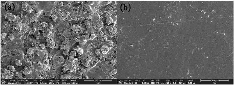
Figure 1. Surface morphologies of Al coating prepared by flame spraying (a) the coating before sealing treatment; (b) the coating sealing treatment.
Figure 2 shows the SEM results of the coating section before and after sealing. From the polished cross section of Figure 2(a), it can be seen that the coating is relatively dense and fused on the surface of the substrate, and the interface cracking phenomenon can be seen. Figure 2(b) shows the effect of hole sealing treatment on the microstructure of the coating cross section. It can be seen from the figure that the cross section structure of the coating after sealing is more compact, without cracks, holes, and pores. The porosity of the coating cross section is measured to be 6.16% and 0.15% before and after sealing, respectively, indicating that the sealing effect is good and the porosity of the coating can be significantly improved.
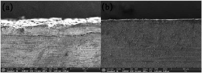
Figure 2. Cross section morphologies of Al coating prepared by flame spraying (a) the coating before sealing treatment; (b) the coating after sealing treatment.
Coating composition analysis
Figure 3 is the EDS-mapping images of the coating surface. It can be seen that pure Al is the main phase structure of the coating, and no obvious alumina phase structure is found in the coating.
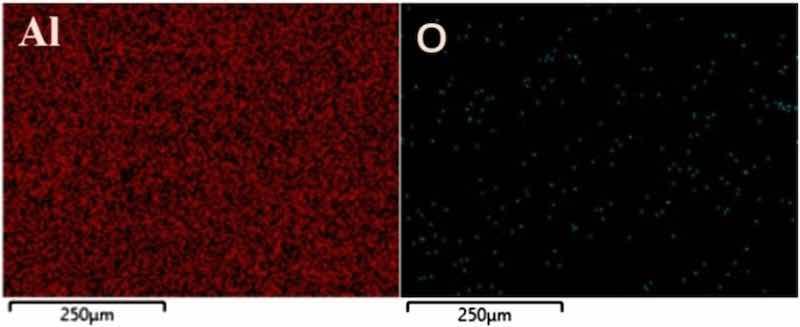
Figure 3. The EDS-mapping images of Al and O elements.
The surface chemical composition of the coating was measured by energy spectrum method, and the results are shown in Table 2. The results show that the main components of the coating are: Al content is 98.57%, O content is 1.43%. This shows that the coating is mainly metal structure, and the oxide content is very small, which can meet the requirements of the metallization treatment of the composite surface, and can realize the function of guiding and releasing the lightning charge on the surface of the composite parts.
Table 2. Surface elements analysis of Al coating prepared by flame spraying.
| Element | Mass fraction/% | Atom fraction/% |
| O | 1.43 | 2.39 |
| Al | 98.57 | 97.61 |
Coating electromagnetic properties
The aluminum conductive layer was prepared according to the spraying parameters in Table 3. After spraying, the flame sprayed aluminum coating resistance was measured by a four-point digital contact resistance tester with a linear discharge distance of 2.54 mm. The resistance value is measured on the coating surface according to the four-probe measurement principle.21 Among them, the coating thickness is 0.08–0.13 mm, and the surface electrical resistance of the coatings is measured in Table 4. It can be seen that the surface electrical resistance is about 0.86 ∼ 0.91 mΩ.
Table 3. Spraying process parameters.
| Compressed air pressure (MPa) | Ethyne pressure (MPa) | Oxygen pressure (MPa) | Moving rate (mm/s) | Spraying distance (mm) | Wire feeding rate (mm/s) |
| ≥0.5 | 0.15∼0.20 | 0.45∼0.60 | 300∼400 | 100∼200 | 35 |
Table 4. Surface electrical resistance of the coatings.
| Coating | Electrical resistance/mΩ | Average/mΩ |
| 1 | 0.86 | 0.89 |
| 2 | 0.89 | |
| 3 | 0.91 | |
| 4 | 0.90 | |
| 5 | 0.88 |
Due to the resin matrix composites themselves not having conductive properties, the surface metallization treatment technology of parts provides a feasible scheme for electromagnetic shielding of resin matrix composites. Shielding effectiveness represents the logarithmic ratio of the received power or field intensity of a shielded material to the received power or field intensity of a shielded material at the same excitation level. The composite plate with aluminum coating was prepared by this process. The size of the plate was 300 mm * 300 mm, and the thickness of aluminum coating was 0.1 mm. The electromagnetic shielding effectiveness test is conducted according to GJB 5239-2004. The test results are shown in Figure 4. It can be seen that the shielding effectiveness is basically greater than 16 dB at 2 ∼ 18 GHz. In the range of 2 ∼ 10 GHz, with the increase of electromagnetic frequency, the shielding efficiency of coating shows an upward trend, and there is a slight decrease in shielding efficiency only in the 7 ∼ 8 GHz region. In the range of 10 ∼ 12 GHz, the shielding effectiveness of the coating shows a downward trend, and the electromagnetic shielding effectiveness drops to 43 dB.
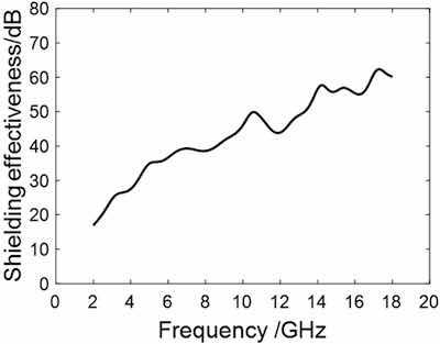 Figure 4. Electromagnetic shielding effectiveness of the coating.The shielding effectiveness of the coating turns to an upward trend in the 12 ∼ 14 GHz region, and the electromagnetic shielding effectiveness rises to 57 dB. Finally, the electromagnetic shielding effectiveness of the coating fluctuates within 55 ∼ 62 dB in the 14 ∼ 18 GHz region. It can be seen from the above analysis that the shielding effectiveness is only slightly less than 35 dB in the 2∼5 GHz region, and the shielding effectiveness is basically greater than 35 dB at 5∼18 GHz, moreover, with the increase of electromagnetic frequency, the shielding efficiency of the coating shows an upward trend. The traditional electromagnetic shielding coating forms a certain electromagnetic shielding effect by adding conductive fillers to the resin matrix, and its shielding efficiency is generally 35 ∼ 40 dB, moreover, with the increase of electromagnetic frequency, the shielding efficiency of the traditional electromagnetic shielding coating shows a downward trend. In addition, the flame spraying aluminum coating thickness is uniform and controllable, the bonding strength is high, and the construction is convenient, so it can be used as an ideal electromagnetic shielding technology.
Bonding strength of aluminum conductive layer
Figure 5 is the SEM graph of the interface between the coating and the matrix. It can be seen that the matrix composite is mainly composed of bright white resin and carbon fiber. By careful observation of the interface morphology of the coating and the matrix, it can be seen that the interface of the coating and the matrix material is well combined, and no obvious burning loss and carbonization of the matrix material is found. This is mainly because the temperature of the matrix can be controlled below 40°C during the spraying process by automatic spraying technology, and there is almost no damage to the matrix material.
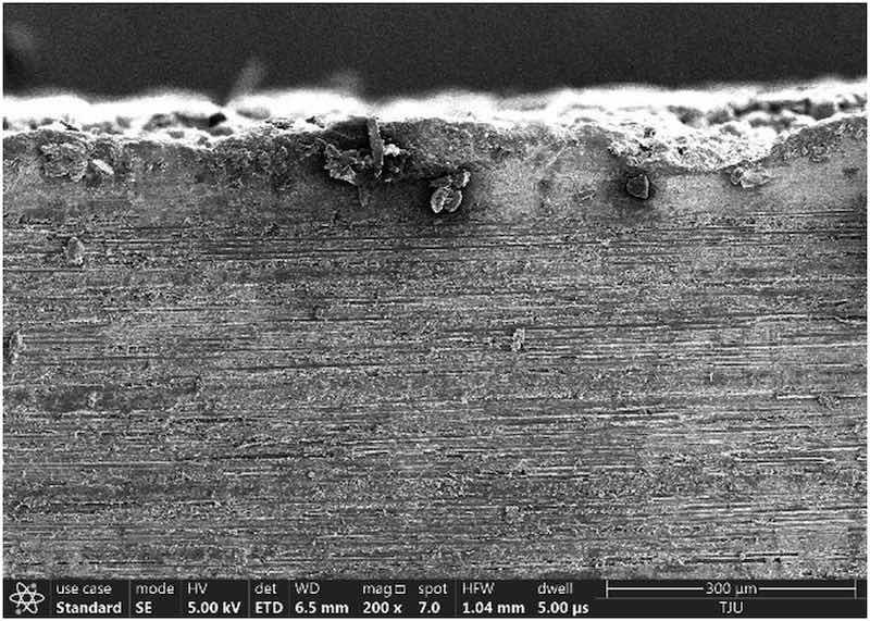
Figure 5. Morphology of coating/substrate interface.
The test results of bond strength are shown in Table 5 and Table 6. The mean bonding strength of the coating without hole sealing adhesive is 7.36 MPa, which is significantly higher than that of the aluminum coating sprayed by similar methods.10, 17, 22 Meanwhile, it can be found from the data analysis in the table that the average bonding strength of the surface coating increases to 21.85 MPa after hole sealing, indicating that the interface bonding strength of the aluminum coating and the composite material can be significantly improved by hole sealing.
Table 5. Bond strength of the coatings before sealing treatment.
| Coating | Diameter/mm | Bond strength/MPa | Average/MPa |
| 1 | 25.4 | 7.23 | 7.36 |
| 2 | 25.4 | 7.86 | |
| 3 | 25.4 | 7.05 | |
| 4 | 25.4 | 7.50 | |
| 5 | 25.4 | 7.18 |
Table 6. Bond strength of the coatings sealing treatment.
| Coating | Diameter/mm | Bond strength/MPa | Average/MPa |
| 1 | 25.4 | 20.91 | 21.85 |
| 2 | 25.4 | 21.67 | |
| 3 | 25.4 | 21.60 | |
| 4 | 25.4 | 22.32 | |
| 5 | 25.4 | 22.75 |
Thermal shock resistance analysis
As can be seen from Table 7, the three sealed samples are put into a box-type electric furnace and heated from 50 ∼ 200°C at intervals of 50°C, kept for 30 min, and then taken out for air cooling for thermal shock test. After repeated heating and cooling of the same samples, it is found that the aluminum coating on the surface of composite material is well combined with the matrix, and the coating surface is intact, compact, without cracks, peeling, stratification and edge warping, indicating that the coating is firmly combined with the matrix. Three test samples for thermal shock resistance are shown in Figure 6.
Table 7. Experimental phenomenon of thermal shock resistance.
| T/°C | Surface observations |
| 50 | No change |
| 100 | No change |
| 150 | No change |
| 200 | No change |
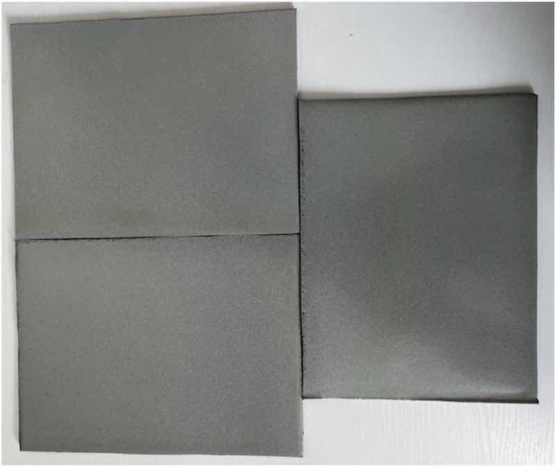
Figure 6. Results of thermal shock resistance.
Low temperature cooling performance analysis
Three sealed low temperature test samples are shown in Figure 7. As can be seen from the figure, after three samples are placed in the cold storage and cooled to 30°C for 1 month, the coating surface of the samples is complete and dense, without cracks, peeling, stratification and edge upturned, indicating that the coating is firmly combined with the substrate.
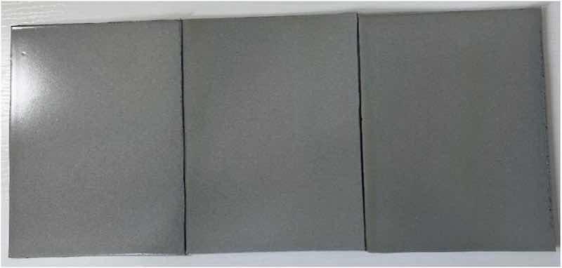
Figure 7. Low temperature cooling test.
Conclusions
(1) A 0.1 mm thick aluminum coating was prepared on the surface of resin matrix composites by automatic flame spraying technology. The interface between the coating and the matrix was well combined. The coating surface was intact and compact, and no cracks, peeling, lamination, edge warping, and other phenomena were found.
(2) The bonding strength reached 7.36 MPa and the surface porosity was about 5.21% before sealing, and the bonding strength reached 21.85 MPa, the surface porosity was about 0.16% after sealing. Furthermore, the main components of the coating was Al content, the oxygen content was only 1.43%.
(3) The surface electrical resistance of the coating was about 0.89 mΩ, and the shielding effectiveness was greater than 35 dB at 5 ∼ 18 GHz, moreover, with the increase of electromagnetic frequency, the shielding efficiency of the coating showed an upward trend. In addition, the coating thickness was uniform and controllable, and the bonding strength was high, thus, it could play the role of electromagnetic shielding.
(4) The aluminum coating prepared by automatic flame spraying aluminum could be used in the extreme cold and high temperature environment of −30°C and 50–200°C for a long time, and the coating surface remains intact, compact, no cracks, peeling, layering, edge upturned, and other phenomena.
Written by Qiang Guo, Junjun Zhu, Chao Li, Peng Tang, Chen Wen, Lan Liu, Tianze Wang, Yeqin Hu, Yingnan Zhao, Ming Zhao, Yulong Feng, Hengyuan Xu and Hai Liu. They are with AVIC Chengdu Aircraft Industrial (Group) Co., Ltd., Chengdu, China.
Declaration of conflict of interests: The authors declare that there is no conflict of interests regarding the publication of this paper.
Funding: The author(s) received no financial support for the research, authorship, and/or publication of this article.
Author contributions: Qiang Guo, Junjun Zhu, Chao Li, and Peng Tang conceived and designed the experiments; Chen Wen, Lan Liu, Tianze Wang, Yeqin Hu, Yingnan Zhao, Ming Zhao, Hai Liu, Hengyuan Xu, and Yulong Feng performed the experiments; Qiang Guo and Chen Wen analyzed the data; Qiang Guo, Junjun Zhu, Chao Li, and Peng Tang contributed reagents and materials; Qiang Guo and Junjun Zhu wrote the paper and all authors read and approved the final manuscript.
References
1. Duan Y, Zhou X, Hou J. Status of manufacturing technology in large aircraft composites wing [J]. Aeronautical Manufacturing Technology 2012; 55(18): 34–37.
2. Yang N. Composite Structure for new generation large commercial jet [J]. Acta Aeronautica et Astronautica Sinica 2008; 44(3): 596–604.
3. Wang B. Application and prospect of composite materials [J]. New Technology and New Products of China 2018; 6: 40–41.
4. Gu Y, Li M, Li Y, et al. Progress on manufacturing technology and process theory of aircraft composite structure[J]. Acta Aeronautica etAstronautica Sinica 2015; 36(8): 2773–2797.
5. Liu X, Yu X, et a1. Axial compression of carbon fiber composite laminates with different protection after lightning strike [J]. Journal of Materials Science and Engineering 2016; 34(3): 375–378.
6. Liang H, Tingxian X, Yang D, et al. Research on the metallization for the surface of bismaleimide-glass fiber composite [J]. Journal of Materials Engineering 2001; 79(11): 17–20.
7. Njuhovic E, Witt A, Kempf M, et al. Influence of the composite surface structure on the peel strength of metallized carbon fibre-reinforced epoxy. Surf Coat Technol 2013; 232(10): 319–325.
8. Xu Y, Liao Z. Technology for spraying the aluminium coating on the part surface of composite material [J]. Hong Du Science and Technology 1999; 4: 6–12.
9. Li L, Wang C, et al. Study on aluminium frame spraying technology [J]. Surface Finishing 2011; 32(7): 17–19.
10. Chaohui J, Li N, et al. Effect of surface pretreatments on the performance of conductive coating of composite material [J]. Welding Technology 2009; 38(10): 16–18.
11. Robitaille F, Yandouzi M, Hind S, et al. Metallic coating of aerospace carbon/epoxy composites by the pulsed gas dynamic spraying process [J]. Surface and Coatings Technology 2009; 203(19):2954–2960.
12. Huonnic N, Abdelghani M, Mertiny P, et al. Deposition and characterization of flame-sprayed aluminum on cured glass and basalt fiber-reinforced epoxy tubes. Surf Coat Technol and Coatings Technology 2010; 205(3):867–873.
13. Zhou X, Chen A, Wu X, et al. Preparation of metallic coatings on polymer matrix composites by cold spray. Surf Coat Technol. Surface and Coatings Technology 2011; 206(1):132–136.
14. Chen Z. Application of flame aluminum spraying technology in carbon fiber/composite aircraft parts [J]. Surface Technology 1998; 27(5): 31–33.
15. Chang X, Han F, et al. Research on aluminum coating by flame spraying [J]. Journal of Chongqing University of Technology (Natural Science) 2012; 26(6): 42–44.
16. Cui Y, Jingying H, et al. Characteristics of A1 coatings fabricated by detonation gun spray on polymer-based composites [J]. Journal of Materials Engineering 2018; 46(6): 120–124.
17. Guanhong S, Xiaodong H, Jiuxing J, et al. Parametric study of AL and A1203 ceramic coatings deposited by air plasma spray onto polymer substrate [J]. Applied Surface Science 2011; 257(17): 7864–7870.
18. Wang R, Song D, Liu W, et al. Effect of arc spraying power on the microstructure and mechanical properties of Zn-Al coating deposited onto carbon fiber reinforced epoxy composites. Applied Surface Science 2010; 257(1): 203–209.
19. Cheng S, Gao J, Liu A, et al. Numerical simulation of temperature field in plasma spraying on polymer matrix composite substrate [J]. Transactions of the China Welding Institution 2006; 27(7): 101–105.
20. Li Q, Li S, Yang W. Preparation of flame sprayed aluminum coating for electrostatic shielding on composite material reinforced with carbon fiber and properties of the coating [J]. Materials Protection 2007; 40(1): 19–21.
21. Liu X, Sun Y, et al. Principle and Application of Four-Probe Technique for Measuring Sheet Resistance [J]. Semiconductor Technology 2004; 29(7): 48–52.
22. Li N, Wang Z, Chaohui J, et al. Effect of spraying temperature on the conductivity of composite material surface [J]. Welding and Joining 2009; (8): 30–33.