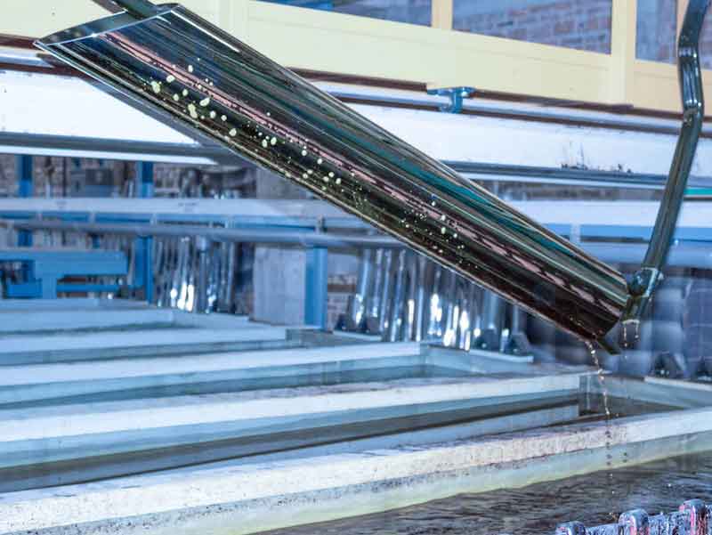
The evolution of the plating process has been a slow one relative to other manufacturing processes.
 Felipe AttiWhile plating has seen some strides in the realm of automation, the majority of manufacturing processes are already fully computer-controlled or progressing to that end.
In attempts to achieve consistent results from plating processes, there has been a huge push in process parameter control. Platers across the board, as well as the markets they serve, have adopted narrow acceptable ranges for solution temperature and chemical concentrations (as well as low tolerance for contaminants). In addition, there is a rising demand for precise control of electric current. Despite said efforts, there are still many variables in the process that make it difficult to achieve consistent results within a narrow range of plating thickness and/or coverage.
Plating Parts Simultaneously
When plating several parts simultaneously, the parts are electrically connected in parallel in a tank. Theoretically, the parts have the same electrical conditions; however, in practice, there will be a variance in the resistance between the parts to the rack and/or the anodes to the tank bussing. In a parallel configuration, the voltage is common, but the electrical current is subject to the inconsistencies of the voltage interactions at each contact point and part being plated. Any difference in potential will result in different electric currents across the parts and/or anodes (this can easily be checked with clamp meters). While the rectifier may deliver the desired current, the process may still produce varying plating thicknesses across the parts.
The simplest way to deal with variance in the plating results is to intentionally over plate. By doing this, the least plated part in the batch will still maintain the minimum specified plating thickness, thus meeting quality standards. The drawback is that many of the parts will have more plating thicknesses than were required. Though effective, over-plating is inefficient and calls for additional costs and waste. While practicing this method, platers use more energy, time, and chemicals than their customers are paying for. Not to mention that parts subject to grinding after processes such as hard chrome plating will require a longer grinding process to remove all of the undesired excess plating.
Plating is a multifaceted process with many factors to consider. Two significant electrical factors that are known to have an influence on plating results are output ripple and accuracy of current measurements.
Narrow Range Low Ripple
- Plating deposition rates (plating speed) are sensitive not only to ASF (Amperes per square foot) but also sensitive to output ripple. The best output from an SCR rectifier with a ripple filter installed is typically 5% ripple at the max output voltage. SCR rectifiers have their output ripple affected by the output settings: the lower the output voltage, the higher the ripple. This condition is exacerbated when the rated voltage of the rectifier is significantly higher than what the respective plating process calls for. The output ripple will also increase as the current is increased.
- The efforts put into controlling other variables (keeping the plating solution temperature and chemical concentration within narrow ranges, investing in computer control to keep the ASF constant for different process recipes, etc.) are futile if the plater does not consider that slight changes in the voltage to keep Amps constant can increase output ripple and cause varying plating thickness in spite of other parameter controls.
- High-quality switch mode rectifiers can deliver ripple below 1% throughout the entire output range.
Accurate Control and Precise Output Voltage and Current Readings
- Old-fashioned rectifiers typically use huge shunts to provide the electric current flow reading. Shunts are resistors made of special material to keep the electrical properties constant regardless of the temperature. By nature, resistors will get hot when there is an electric current flowing through them, resulting in losses in the circuit.
- Some high-quality switch mode rectifiers supply DC current split in modules but also do so accurately with modular electric current measuring through Hall Effect sensors (no shunt resistors) and thus achieve current control within 1% of the rated output.
Split Modular Output
There is another feature of high-quality switch mode modular rectifiers that can be useful in achieving uniform plating thickness among:
- Each rack of parts (or a single part) can be connected separately to a negative pole from a power module output (or from a block of power modules) while having common positive bussing connected to all anodes of a plating tank. Subsequently, each output will compensate for the voltage on each part in order to achieve equal electric current. Maintaining an equal electric charge (A.h) will deliver equal plating thickness among the parts being plated at the same time.
- Similarly, each anode can be connected separately to a positive pole from a power module output (or from a block of power modules) while having common negative bussing connected to the part in a plating tank. Here each output will compensate for the voltage on each anode in order to achieve equal electric current and consequently equal electric charge (A.h) to deliver uniform plating thickness around the part being plated with several anodes at the same time: hard chrome on rolls and cylinders.
High-quality switch mode modular rectifiers allow you to minimize intentional over plating, which means a potential reduction in:
- Plating times, thus plating more batches per day;
- Energy and raw-material consumption (anodes and chemicals).
Below we can see an example of a typical hard chrome plating batch, with eight parts connected in parallel to the one rectifier:

As the part being plated with the lowest current (353 Amp) tells when the plating batch is completed, if the goal is to plate 1.5 mils (38 microns), the average plated thickness among the parts will be 15% above the goal. If each rack is connected to a separate output from a modular power supply, those differences in the resistance of each part will no longer be translated into different electric currents as seen above, but in different voltages to achieve the exact same electric current among all the parts, saving 15% of energy, raw materials, and plating time.
Deviation
Amps Thickness Surface Currentity Density
| Total | 3257 | % | Mils | Microns | ASF | ASI | A/dm2 |
| Min | 353 | goal | 1.5 | 38 | 362 | 2.516 | 39 |
| Average | 407 | 15.30% | 1.73 | 43.83 | 418 | 2.9018 | 45 |
| Max | 458 | 29.70% | 1.94 | 49.3 | 470 | 3.2644 | 50.6 |
Felipe Atti is the Senior Applications Engineer at KraftPowercon, Inc. Before joining the KraftPowercon team, he has been in the hard chrome plating business since his industrial apprenticeship training in electronics in 1991. He earned his BSc degree in Mechanical Engineering from Universidade de Caxias do Sul, Brazil, and holds an MBA degree from Fundacao Getulio Vargas, Brazil. To schedule a meeting with Felipe at the 2022 NASF SUR/FIN show, schedule online at https://outlook.office365.com/owa/calendar/KraftPowercon@kraftpowercon.com/bookings/


