This study investigates the effect of the microstructure of electrodeposited ZnNi coatings, in particular pores and microcracks, on hydrogen diffusion characteristics at room temperature.
The hydrogen permeation behavior and thermal desorption spectra of electrodeposited ZnNi microand nanostructured coatings were studied and compared. The microstructures of the coatings were observed using a scanning electron microscope. The results showed that the presence of microcracks significantly influences the hydrogen diffusion behavior: in microstructured ZnNi hydrogen can diffuse along the microcracks due to the large number of microcracks present, leading to higher hydrogen absorption during electrochemical charging. Also, the high grain boundary density in the nanostructured coating leads to the presence of a larger number of strong H traps, and thus lower diffusible H content.
1. Introduction
Zinc coatings are conventionally used to protect steel components and equipment from corrosion. This is because zinc has a more negative corrosion potential than steel, and thus acts as a sacrificial coating [1–3]. According to the literature [4–8], Zn-Ni, Zn-Fe, and Zn-Co coatings on steel provide better corrosion resistance than pure zinc coatings, and indeed Zn-Ni alloy coatings have become one of the preferred ecofriendly alternatives to widely used toxic cadmium coatings.
It is widely recognized that diffusible hydrogen, even in quantities less than 1 ppm, embrittles high-strength steel components and thus changes the fracture mode to the detriment of high-strength steel [7–9]. Hydrogen can be initially present in the alloy either internally, as a result of steel-making processes or finishing processes such as acid pickling and electroplating, or externally due to the service conditions. The hydrogen in steel is categorized as either residual or diffusible hydrogen. The residual hydrogen is trapped permanently in the steel and cannot affect hydrogen embrittlement until the irreversible traps are saturated with hydrogen. Above a critical concentration of hydrogen, hydrogen might decrease the cohesive strength between the atoms and initiate cracks at these irreversible trapping sites, following the hydrogen-enhanced decohesion (HEDE) mechanism [10–13]. In addition to the HEDE mechanism, hydrogen-induced enhancement of the mobility of dislocations in these traps has been observed [14], revealing that the hydrogen-enhanced localized plasticity (HELP) mechanism might also be active. The coexistence of HEDE and HELP mechanisms has led to the proposal that the synergistic action of both HELP and HEDE mechanisms (HELP + HEDE model) governs hydrogen embrittlement in steels. By contrast, diffusible hydrogen and reversibly trapped hydrogen are able to escape from their traps and reach other traps or crack tips, causing enhanced hydrogen embrittlement [15–20]. . Therefore, steels should be treated to prevent the absorption of hydrogen and hinder its progress through the steel lattice.
It has been reported that the hydrogen permeability of electrodeposited ZnNi membranes is considerably lower than that of ferritic steel [21], which would make it a good candidate for a hydrogen barrier coating. Although the electrodeposition process itself can introduce hydrogen into the steel, post-electrodeposition baking immediately after electrodeposition can reverse the effects of hydrogen embrittlement in most cases. More importantly, it has been reported [22] that ZnNi coatings contain defects such as pores, which can be observed in different microstructural situations such as coating/substrate interfaces. These defects in ZnNi coatings mean that there are more hydrogen diffusion paths from the surface to the substrate, leading to the absorption of more external hydrogen by the material during exposure to hydrogen-containing solutions or environments. Therefore, in order to improve the hydrogen embrittlement behavior of the ZnNi coatings it is necessary to reduce the number of diffusion pathways for hydrogen.
It has been reported in several studies [23,24] that nanostructured coatings contain a lower amount of defects. Therefore, a promising approach would be to use a modified electrodeposition technique and optimize the parameters for deposition of a nanostructured ZnNi coating to improve resistance to hydrogen diffusion in the coating. In the present study, optimized electrodeposition of a ZnNi coating will be used to produce a nanostructured ZnNi coating with high resistance to hydrogen diffusion. The diffusion coefficient of the ZnNi-coated alloy will be measured using electrochemical hydrogen permeation experiments and will be compared with the results obtained for a microstructured ZnNi coating. Thermal desorption spectroscopy (TDS) will also be used to study the hydrogen trapped in ZnNi-coated samples. These investigations and the obtained results could pave the way to develop a coating which is highly resistant to the detrimental effects of hydrogen on high-strength steels when subjected to H-containing solutions and atmospheres.
2. Experimental Procedures
2.1. Substrate material
A ferritic steel 36CrNiMo4 with the chemical composition (Fe-0.35C0.1Si-0.5Mn-1.1Ni-1.1Cr-0.2Mo in mass%) was selected as the substrate. Due to its high strength and toughness and very good fatigue resistance, this steel is widely used in vehicle and general structural applications including plane, propeller, or apparatus shafts, partner bars, and plane landing gear sections.
To prepare the steel as substrate specimens, the surfaces of steel specimens were mechanically polished with 600–2000 emery grit papers followed by alumina polishing to achieve a mirror surface. Subsequently, the specimens were cleaned in an ultrasonic bath prior to coating.
2.2. Coating processes
An alkaline plating solution with a Zn/Ni metal concentration of 11/ 1 ratio was utilized. The concentrations of bath constituents were 10.0Zn-1.0Ni-59Na2CO3-135.0NaOH (g l− 1). During the electrodeposition process, the pH was maintained in the range 11–13 at 30 ◦C with a current density of 27 mA cm− 2. To produce nanostructured and microstructured ZnNi coatings, nano-sized and micro-sized primary powders, respectively, were used to deposit ZnNi coatings on the substrates. For deposition of a nanostructured coating on the specimen, 10 mmol l− 1of glycerol was added to the solution [25].
2.3. Microstructure characterization
The microstructures of microand nanostructured ZnNi coatings were studied using a scanning electron microscope (SEM/FE-SEM, Zeiss Supra 55, Germany). These observations reveal the morphology of the coating surfaces, and the structure of the coatings. Cross-sectional observations of the microstructure were also conducted on the specimens, which were cut by a diamond saw, polished by grit emery papers (up to 1500) and then polished to a mirror surface by 0.1 μ alumina suspension. Furthermore, the composition of the coatings was studied by XRD, using a Rigaku Ultima IV diffractometer (CuKα1 radiation with 40 kV and 30 mA). The XRD measurements were carried out with 2θ in the range 30–80◦, a scan speed of 0.1◦/min and a step size of 0.01◦.
2.4. Hydrogen electrochemical diffusion experiments
The electrochemical permeation tests were performed in a Devanathan–Stachurski double cell [26,27]. The specimens with the size of 30 mm × 30mm × 1 mm were placed between charging and oxidation sides (cathodic-anodic) with the side coated with Pd facing the oxidation cell. This Pd coating on the oxidation side (on the backside of the sample, not the coated surfaces) leads to a faster oxidation rate, hindering recombination to H2 and avoiding passive layer formation. An aqueous solution containing 3.5 % NaCl with the addition of 1 g/l thiourea were used in the charging cell, while 0.1 mol/l NaOH was used as the solution for the oxidation cell. The thiourea is added to inhibit the recombination of hydrogen atoms to form molecular hydrogen. We used a saturated KCl reference electrode and a Pt counter electrode. To remove dissolved oxygen, both cells were purged with argon, and the temperature in the cells was kept at 25 ◦C. The charging cell was operated with a current density of 1 mA/cm2, and the potential of the oxidation cell was maintained at 510 mV vs. the standard hydrogen electrode (SHE).
2.5. Electrochemical hydrogen charging
Hydrogen was introduced into the specimen by an electrochemical hydrogen pre-charging method using a sulphuric acid solution with a pH of 2.5 containing 1 g/l thiourea as a hydrogen recombination inhibitor at a constant cathodic current density of 10 mA.cm− 2 for 24 h. During electrochemical charging, the specimen and the Pt electrode are used as the cathode and anode, respectively.
2.6. Thermal desorption spectroscopy
After the hydrogen electrochemical charging process, the coatings were removed as quickly as possible, and then the specimens were immediately dipped into liquid nitrogen to avoid the escape of hydrogen. TDS is a technique used to measure the desorbed hydrogen content by increasing the temperature. In TDS, the sample is heated in a vacuum chamber and the partial pressure of hydrogen released as a result of heating can be measured. The samples were tested using TDS at a constant heating rate of 300 ◦C/h. The total amount of desorbed hydrogen from time t1 to time t2 can be measured as follows [28–30]:
where K, S, V, and P are the molecular conversion factor, the exhaust rate of the vacuum pump, the volume of the sample, and the partial pressure of hydrogen in the chamber, respectively.
3. Results and Discussion
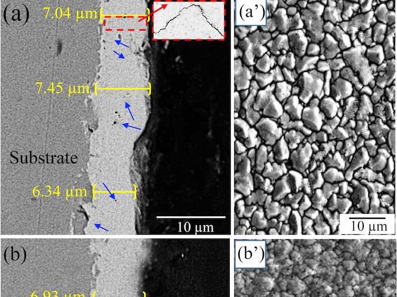
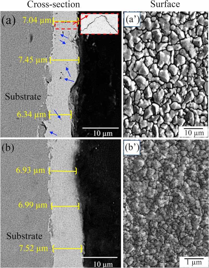 Fig. 1. SEM micrographs of the cross-sections and surfaces of (a, aʹ) a microstructured ZnNi coating, and (b, bʹ) a nanostructured ZnNi coating.Fig. 1 shows some SEM images of the surface and cross-sections of the coated samples. For both ZnNi coating types, the average thickness was 6.9–7.2 μm, indicating that the coating thickness was not significantly different between the coating types (Fig. 1a,b). The grain size of the coating in Fig. 1(aʹ) is between 1 and 10 μm (microstructured), while that in Fig. 1(bʹ) is between 50 and 800 nm (nanostructured). This means that the density of grain boundaries (GBs) in the nanostructured coating is higher than that in the microstructured coating. It was also observed that the borders of the pores in the surface of the microstructured ZnNi act as a nucleus for microcracks (Fig. 1aʹ). Furthermore, the cross-section of the microstructured ZnNi coating shows some voids and microcracks (blue arrows in Fig. 1a) in the coating. These microcracks and voids were not observed in the cross-section of the nanostructured ZnNi coating (Fig. 1b), and fewer cracks/voids are present on the surface of this type of coating (Fig. 1bʹ). Fig. 2 shows the XRD patterns obtained from specimens with nanoand microstructured coatings. The results indicate that the coatings contain the γ-phase (Ni5Zn21), and that both nanoand microstructured coatings have a similar phase composition.
Fig. 3 presents a schematic representation of the double cell for the electrochemical permeation test, and the results obtained by this method, which are shown as permeation current density versus time. It is apparent that the permeation current density of the nanostructured ZnNi-coated specimen is higher than that of the microstructured ZnNicoated specimen. From the resulting graphs (transient), the diffusion coefficient, the permeation flux at the steady state, and the concentration of hydrogen in the substrate can be calculated using the following equations [1,31,32]:
where Deff is the diffusion coefficient (effective), C0 is the H ion concentration in the substrate, Jss is the permeation flux, Iss is the hydrogen permeation current density for the steady-state condition, tlag is the time lag (which is related to the time span required for the oxidation current to reach 0.63 times the steady-state value), L is the membrane thickness, and A is the exposed area.
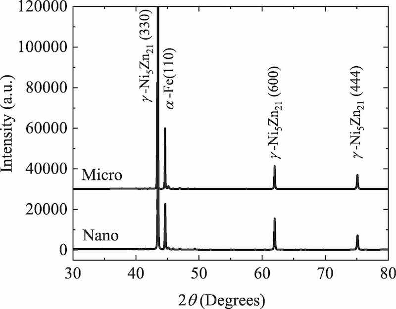 Fig. 2. XRD patterns of nanostructured ZnNi-coated and microstructured ZnNi- coated specimens.It can be understood from Fig. 3 that the microstructured ZnNicoated specimen is relatively permeable to hydrogen in the atomic form due to its short breakthrough time and relatively high permeation current density. However, the specimen with a nanostructured ZnNi coating offers a strong barrier to hydrogen diffusing to the substrate. The permeation current density of the nanostructured ZnNi-coated specimen was only about 19% of that of the microstructured ZnNi-coated specimen. In addition, the breakthrough time was drastically increased in comparison with the microstructured ZnNi-coated specimen. Based on Eqs. (2)–(4), the diffusion coefficient, subsurface hydrogen, and permeation flux were calculated and are listed in Table 1. The results appear to be consistent with the results reported by Sriraman et al. [33], where a coating with a lower number of cracks or voids shows lower hydrogen permeability.
Table 1: Calculated permeation parameters and total hydrogen content obtained from TDS results and Eq. (1) for nano- and microstructured ZnNi-coated specimens.
| Coating | Diffusion coefficient; Deff (cm2.s−1) | Permeation flux; Jss (mol.s−1. cm−2) | Total content of H obtained by TDS (mass ppm) |
| Nanostructured ZnNi coating | 1.21 × 10⁻⁹ | 1.15 × 10⁻¹² | 0.113 |
| Microstructured ZnNi coating | 10.13 × 10⁻⁹ | 6.48 × 10⁻¹² | 2.120 |
Fig. 4 shows thermal desorption spectra obtained with and without electrochemical hydrogen charging. Fig. 4(a) and 4(b) indicate that the hydrogen desorption rate of uncharged specimens with nanoand microstructured coatings was very low and comparable. In the nanostructured coating, the hydrogen atoms were uniformly distributed. However, in the microstructured ZnNi-coated specimen, the hydrogen atoms tend to accumulate at relatively weak traps, meaning that more diffusible hydrogen atoms are available. Fig. 4(c) and 4(d) show the TDS results of H-charged specimens. Interestingly, the desorbed hydrogen content from the nanostructured ZnNi-coated specimen is considerably lower than that from the specimen with a microstructured ZnNi coating. According to the measured TDS results, a considerably lower hydrogen content was obtained for the electrochemically charged specimen with a nanostructured ZnNi coating (Table 1). The results obtained by TDS are in good agreement with the hydrogen permeation results, where a lower diffusion coefficient and lower hydrogen permeation were obtained in the specimen with a nanostructured ZnNi coating.
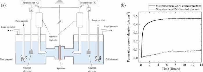 Fig. 3. (a) Schematic representation of the double cell used for electrochemical permeation tests, and (b) permeation curves of nanostructured ZnNi-coated and microstructured ZnNi-coated specimens.
This can be explained by the following factors: (i) absorption of hydrogen during the initial electrodeposition process must be almost the same in both specimens due to the electrodeposition process having a similar efficiency [33] for both coatings that is 65%. (ii) The main difference between the coatings is the presence of a different number of cracks and voids that can act as possible hydrogen escape pathways in the nanostructured and microstructured coatings (Fig. 1a and 1b). A significant amount of hydrogen (Fig. 4d) can enter the substrate during hydrogen electrochemical charging due to the larger number of hydrogen pathways (cracks) and higher hydrogen permeability of the microstructured coating (as shown schematically in Fig. 5).
 Fig. 4. Thermal desorption spectra for (a) an uncharged specimen with a nanostructured ZnNi coating, (b) an uncharged specimen with a microstructured ZnNi coating, (c) a H-charged specimen with a nanostructured ZnNi coating, and (d) a H-charged specimen with a microstructured ZnNi coating.However, in the nanostructured ZnNi coating, the smaller number of hydrogen pathways results in a lower permeability to hydrogen, a lower hydrogen diffusion coefficient, and lower diffusible hydrogen content (as shown schematically in Fig. 5). The smaller number of hydrogen pathways in the nanostructured coating also contributes to more sluggish hydrogen charging compared to the microstructured coating, and lower hydrogen absorption during electrochemical charging (Fig. 4c). (iii) As revealed in Fig. 1aʹ and 1bʹ, the grain size of the nanostructured coating is smaller than that of the microstructured coating (higher density of GBs in the nanostructured coating than in the microstructured coating). As reported in several studies [34,35], GBs are strong H trapping sites, and the H trapping is irreversible.
These strong traps may not be revealed by TDS due to the very high temperature of the traps [28,29,36]. As described in Fig. 5, a large number of strong H traps (GBs) in the nanostructured coating leads to a decrease in the amount of diffusible hydrogen and will eventually decrease the susceptibility to hydrogen embrittlement. These results show that the nanostructured coating is a hydrogen barrier coating and the production of such hydrogen barrier coatings is closely related to the integrity and compactness of the coating as well as a large number of strong H traps.
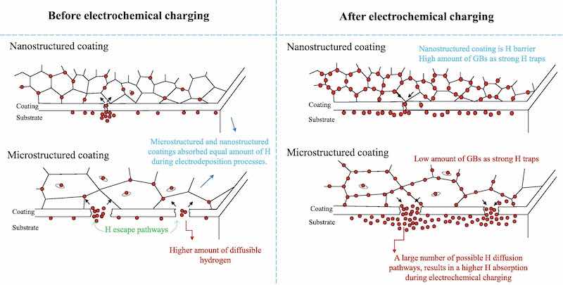 Fig. 5. Schematic representation of coating performance against hydrogen under the different conditions considered in the current study.In the present work, it is shown that the structure of the coating produced by modifying the electrodeposition process decreases hydrogen permeability and can change the hydrogen trapping status. This is therefore an important factor in designing a hydrogen-resistant coating. It is also reported that ferritic steel with a nanostructured ZnNi coating has excellent resistance to hydrogen, due to the very low number of defects such as microcracks and pores, combined with a very low diffusion coefficient, and a high density of strong H traps.
4. Conclusions
The following conclusions can be deduced from the current study:
- Nanostructured ZnNi coatings can be considered to be hydrogenresistant, due to their very low hydrogen diffusion coefficient and the low amount of hydrogen absorbed by the substrate.
- The very small number of defects such as pores and microcracks in the nanostructured ZnNi coating led to very low absorption of hydrogen during electrochemical hydrogen charging, while the
- A higher density of grain boundaries (strong H traps) in the nanostructured coating means that this coating has more possibly irreversible H traps compared with the microstructured coating. This also affects the diffusible hydrogen content, which can determine the behavior of the coating under hydrogen charging conditions.
- The amount of hydrogen obtained using the TDS technique for the uncharged specimen with a nanostructured ZnNi coating is very low, and comparable to that for the uncharged specimen with a microstructured ZnNi coating. The diffusible hydrogen content is higher in the microstructured ZnNi coating.
Masoud Moshtaghi and Gregor Mori are Chair of General and Analytical Chemistry, Montanuniversita ̈t Leoben in Austria; Mahdieh Safyari is with the Institute for Materials Research, Tohoku University, Japan.
Declaration of Competing Interest: The authors declare that they have no known competing financial interests or personal relationships that could have appeared to influence the work reported in this paper.
Acknowledgement: The authors appreciate helpful discussions and resources provided by Prof. S. Kuramoto, and F. Abbasi.
References
[1] K.R. Sriraman, H.W. Strauss, S. Brahimi, R.R. Chromik, J.A. Szpunar, J.H. Osborne, S. Yue, Tribol. Int. 56 (2012) 107–120, https://doi.org/10.1016/j. triboint.2012.06.008.
[2] K.R. Sriraman, S. Brahimi, J.A. Szpunar, J.H. Osborne, S. Yue, Surf. Coat. Technol. 224 (2013) 126–137, https://doi.org/10.1016/j.surfcoat.2013.03.010.
[3] A. Conde, M.A. Arenas, J.J. de Damborenea, Corros. Sci. 53 (2011) 1489–1497, https://doi.org/10.1016/j.corsci.2011.01.021.
[4] P. Ganesan, S.P. Kumaraguru, B.N. Popov, Surf. Coat. Technol. 201 (2007) 7896–7904, https://doi.org/10.1016/j.surfcoat.2007.03.033.
[5] M.P. Waalkes, J. Inorg. Biochem. 79 (2000) 241–244, https://doi.org/10.1016/ S0162-0134(00)00009-X.
[6] M. Ferreira Fernandes, J.R.M. dos Santos, V.M. de Oliveira Velloso, H.J.
C. Voorwald, J. Mater. Eng. Perform. 29 (2020) 1567–1578, https://doi.org/ 10.1007/s11665-020-04669-1.
[7] H.K.D.H. Bhadeshia, ISIJ Int. 56 (2016) 24–36, https://doi.org/10.2355/ isijinternational.ISIJINT-2015-430.
[8] K. Takashima, R. Han, K. Yokoyama, Y. Funakawa, ISIJ Int. 59 (2019) 2327–2333, https://doi.org/10.2355/isijinternational.ISIJINT-2019-219.
[9] T. Omura, J. Nakamura, ISIJ Int. 52 (2012) 234–239, https://doi.org/10.2355/ isijinternational.52.234. Electrochemistry Communications 134 (2022) 107169
[10] M. Moshtaghi, M. Safyari, S. Kuramoto, T. Hojo, Int. J. Hydrog. Energy 46 (2021) 8285–8299, https://doi.org/10.1016/j.ijhydene.2020.12.028.
[11] M. Safyari, T. Hojo, M. Moshtaghi, Vacuum 192 (2021), 110489, https://doi.org/ 10.1016/j.vacuum.2021.110489.
[12] M. Safyari, M. Moshtaghi, S. Kuramoto, Vacuum 172 (2020), 109057, https://doi. org/10.1016/j.vacuum.2019.109057.
[13] M. Safyari, M. Moshtaghi, T. Hojo, E. Akiyama, Corros. Sci. 194 (2022), 109895, https://doi.org/10.2320/matertrans.L-M2010825.
[14] D.F. Teter, I.M. Robertson, H.K. Birnbaum, Acta Mater. 49 (2001) 4313–4323, https://doi.org/10.1016/S1359-6454(01)00301-9.
[15] M.B. Djukic, G.M. Bakic, V. Sijacki Zeravcic, A. Sedmak, B. Rajicic, Eng. Fract. Mech. 216 (2019) 106528. https://doi.org/10.1016/j.engfracmech.2019.106528.
[16] M.L. Martin, M.J. Connolly, F.W. DelRio, A.J. Slifka, Appl. Phys. Rev. 7 (2020), 041301, https://doi.org/10.1063/5.0012851.
[17] M.Wasim,M.B.Djukic,T.D.Ngo,Eng.Fail.Anal.123(2021),105312,https://doi. org/10.1016/j.engfailanal.2021.105312.
[18] M.B.Djukic,V.SijackiZeravcic,G.M.Bakic,A.Sedmak,B.Rajicic,Eng.Fail.Anal. 58 (2015) 485–498, https://doi.org/10.1016/j.engfailanal.2015.05.017.
[19] B. Sun, D. Wang, X. Lu, D. Wan, D. Ponge, X. Zhang, Acta Metall. Sin. Engl. Lett. 34 (2021) 741–754, https://doi.org/10.1007/s40195-021-01233-1.
[20] Q.Liu,Q.Zhou,J.Venezuela,M.Zhang,J.Wang,A.Atrens,Corros.Rev.34(2016) 127–152, https://doi.org/10.1515/corrrev-2015-0083.
[21] D.H. Coleman, B.N. Popov, R.E. White, J. Appl. Electrochem. 28 (1998) 889–894, https://doi.org/10.1023/A:1003408230951.
[22] D. Figueroa, M.J. Robinson, Corros. Sci. 50 (2008) 1066–1079, https://doi.org/ 10.1016/j.corsci.2007.11.023.
[23] L. Wang, Y. Wang, X.G. Sun, J.Q. He, Z.Y. Pan, Y. Zhou, P.L. Wu, Mater. Des. 32 (2011) 36–47, https://doi.org/10.1016/j.matdes.2010.06.040.
[24] X.Lin,Y.Zeng,X.Zheng,C.Ding,Surf.Coat.Technol.195(2005)85–90,https:// doi.org/10.1016/j.surfcoat.2004.08.193.
[25] V.R. Rao, A.C. Hegde, Metall. Mater. Trans. B 44 (2013) 1236–1242, https://doi. org/10.1007/s11663-013-9868-y.
[26] M.A.V. Devanathan, Z. Stachurski, Proc. R. Soc. Lond. Ser. Math. Phys. Sci. 270 (1962) 90–102, https://doi.org/10.1098/rspa.1962.0205.
[27] S.J. Kim, D.W. Yun, D.W. Suh, K.Y. Kim, Electrochem. Commun. 24 (2012) 112–115, https://doi.org/10.1016/j.elecom.2012.09.002.
[28] M. Safyari, M. Moshtaghi, S. Kuramoto, J. Alloys Compd. 855 (2021), 157300, https://doi.org/10.1016/j.jallcom.2020.157300.
[29] M. Safyari, M. Moshtaghi, S. Kuramoto, Mater. Sci. Eng. A 799 (2021), 139850, https://doi.org/10.1016/j.msea.2020.139850.
[30] H. Luo, Z. Li, Y.-H. Chen, D. Ponge, M. Rohwerder, D. Raabe, Electrochem. Commun. 79 (2017) 28–32, https://doi.org/10.1016/j.elecom.2017.04.013.
[31] N. Boes, H. Züchner, J. Common Met. 49 (1976) 223–240, https://doi.org/10.1016/0022-5088(76)90037-0.
[32] J.G. Early, Acta Metall. 26 (1978) 1215–1223, https://doi.org/10.1016/0001-6160(78)90005-6.
[33] K.R. Sriraman, S. Brahimi, J.A. Szpunar, S. Yue, J. Appl. Electrochem. 43 (2013) 441–451, https://doi.org/10.1007/s10800-013-0529-2.
[34] S. Wang, M.L. Martin, I.M. Robertson, P. Sofronis, Acta Mater. 107 (2016) 279–288, https://doi.org/10.1016/j.actamat.2016.01.067.
[35] G.M. Pressouyre, Metall. Trans. A 10 (1979) 1571–1573, https://doi.org/10.1007/ BF02812023.
[36] G.A. Young, J.R. Scully, Acta Mater. 46 (1998) 6337–6349, https://doi.org/ 10.1016/S1359-6454(98)00333-4.