A reader says they work for an engineering firm that is applying for a state air permit, and the permit forms require me to estimate the emissions coming off a number of metal finishing processes.
“We have not been able to locate any information on how this can be done,” the reader says. “Could you provide any assistance? Also, what is your opinion on push-pull ventilation, especially for hard chromium plating operations? Lastly, what goes into the design of a good ventilation system for a metal finishing process tank?”
Although this subject has been broached with me before, this question comes up so frequently that we will provide as detailed an answer as possible.
The sad fact is that there is no good reference available to allow for scientific estimation of the emissions you are concerned with. Several years ago, AESF and EPA sponsored a study by Dr. John Dietz of the University of Central Florida, which provided equations for the estimation of emissions from chromium plating operations. The “general” equation for obtaining a conservative estimate is reproduced here for those who don’t have ready access to a technical library:
Cr = 49,000 + 0.0016 x Amp-hr x Vol
where Cr = mass emission of hexavalent chromium (excluding control equipment); Amp-hr = Ampere-hours applied during the estimation period; Vol = the plating tank volume.
Beyond chromium plating operations, there currently is no scientific estimation method available. We, therefore, resort to a crude estimation technique developed by the New York State Department of Environmental Conservation, which published an “Environmental Conservation Handbook” in 1975. Chapter 3600 of this book, section 3620, provides the following equation for calculating an emission rate potential (ERP):
ERP = % Gassing Rate Factor x process makeup rate in lb/hr
The gassing rate is obtained from tables that are in chapter 3700 of the same book, but you can also find gassing rates in the Electroplating & Engineering Handbook, available for purchase from AESF. The gassing rates are assigned a numerical percentage as follows:
| Gassing Rate | - | % Factor |
| 1 | or High | 5 |
| 1.5 | Medium-High | 4 |
| 2 | Medium | 3 |
| 2.5 | Medium-Low | 2 |
| 3 | Low | 1 |
| 4 | Nil | 0 |
To make the calculation, you need to know the above % factor and the makeup rate of the process. The makeup rate is the lb/hr of water and chemicals that are added back to the process while it is operating.
For example: If the process is pickling iron/steel in hydrochloric acid, the gassing rate is listed in chapter 3700 of the referenced handbook as “2,” indicating a gassing factor of 3 percent. If our makeup rate of water and hydrochloric acid happens to be 8 lb/hr, the emissions from this process are estimated as follows:
ERP = 0.03 x 8 = 0.24 lb/hr
Note: The few times we have had an occasion to actually test emissions off a process that had been estimated, using this technique, the estimate was significantly higher than the actual emissions. This is all that is currently available, however, until more money is spent to provide the industry with better estimation techniques.
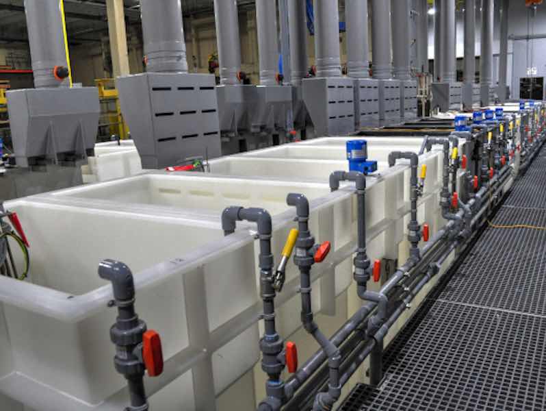
As for push-pull ventilation systems on hard chromium plating processes, I don’t like them at all unless the system is designed such that the “mess” of cables, clamps, and copper bus-work that typically resides on top of the plating tank is out of the way of the pushing air and pull duct. An example of how not to do it is shown in the accompanying photo, which was taken at a large aircraft re-work facility a few years ago.
As for ventilation design tips, I will draw upon the expertise of Ron Roberts, HVAC specialist at Lockwood Greene Engineers in Spartanburg, SC, who states:
Ventilation Design Considerations
Proper ventilation of a metal finishing process is covered by OSHA regulations found in 29 CFR section 1910.94. Complete coverage of ventilation design is beyond the scope of this article, but here are some basics:
- The process must first be evaluated for “Hazard Potential.” For example, in chromium plating, this potential hazard rating is “A,” due to toxicity (OSHA PEL for chromic acid mist is 0.1 mg/M3).
- The rate of gas or mist evolution of the process is “High,” yielding a gassing rate of “1.”
- The OSHA specified capture velocity of a combination of hazard “A” and Gassing rate “1” is 150 feet per minute for a lateral exhaust hood in an undisturbed location. You would need to increase this value if you have cross drafts around the plating tank or if the loading dock door is nearby. It is best to assume that you will never have an undisturbed location.
- OSHA specifies different ventilation rates depending on the ratio obtained when dividing the width of the tank by the length. For example, a tank that is 2 ft wide and 4 ft long would have a ratio of 2/4 = 0.5, and according to the OSHA table shown below, would require 260 cfm per square foot of tank surface area if the tank is up against a wall or 340 cfm per square foot, if the tank is free standing. The total exhaust rate for a 2x4 foot tank would then be 260 x 2 x 4 = 2080 cfm.
The capture velocity needs to be balanced with the exhaust flow rate, depending on the design of the exhaust hood. It can be equipped with or without baffles and side panels. You’ll need to review ventilation manuals to get the relationships. For example, for a tank 2 ft wide and 4 ft long, it takes about 225 cfm/ft2 to achieve a capture velocity of 150 fpm (for chromium plating, with a lateral- slot exhaust hood, with baffle), while the same capture velocity can be achieved with about 150 cfm/ft2 if the exhaust hood has side panels. The addition or extension of side panels can also improve the efficiency of an exhaust system by reducing cross drafts. The side panels should be extended as far out from the exhaust hood as work practices allow. Lower exhaust rates translate into lower emissions (in some cases) and lower energy bills (in all cases), but be sure you remain within OSHA standards for worker exposure.
You can overdo a good thing. High exhaust rates may increase capture efficiency, but too high of an exhaust rate tends to “vacuum” out mist particles that ordinarily might fall back into the solution.
If down-draft ventilation ducts are employed, a vertical baffle installed on the top of the duct tends to maximize capture velocity over a greater distance across the width of the tank and the airspace above the tank (updraft ducts “automatically” employ a vertical baffle). The height of this baffle should approach the width of the tank (assuming the baffle won’t interfere with the travel of work over the tank) if ventilation is only from one side.
Cross-draft velocities at exhausted tanks should not be greater than 75 ft/ min (0.4 m/sec) to avoid excessive fugitive emissions and disruption of mist capture by the exhaust hood. On long tanks, the pull hood/plenum should be divided, so that exhaust air is evenly drawn in along the length of the hood. The capture efficiency can be measured using tracer gas or smoke testing.
Some Final Tips
It also is a good idea to orient long tanks so that general room air drafts go across the narrow dimension rather than along the longer one.
Excessive push air can disrupt emission capture. The push air needs to be coordinated with the pull air. Slots are not as effective at pushing air and creating a curtain as jets (holes). The push jets should be directed to the centerline of the tank’s liquid surface. The push pipe is reduced in size in equal sections across the tank to maintain an equal air velocity. Volume dampers and manual shut-off allow for the operator to fine-tune the push and also shut it off during immersion of a large part that will block the pushing air.
As you can see by now, there is a lot of thought and engineering that goes into a successful process ventilation system.
| Tank Width/Length | cfm/ft2 Control Velocity |
| 0.0 - 0.09 | 150 |
| 0.1 - 0.24 | 190 |
| 0.25 - 0.49 | 225 |
| 0.5 - 0.99 | 260 |
| 1.0 - 2.0 | 300 |