A finishing operation with a single automatic plating line was having trouble with how its team was racking parts.
 Frank AltmayerIt seemed that the workers did not respect the plating racks, nor did they pay attention to even the most basic racking principles. As a result, their plated part quality varies more than it should, and their productivity is not near the goal their management has set.
Parts are mounted on racks any time that they must be firmly held in place and not allowed to touch each other during processing. Otherwise, barrel plating is always more economical than rack plating.
Let’s break good racking practice down to some basic issues:
1. Constant part surface area
On an automated line, each part needs to be measured for surface area. Any bare surface of the rack that will be exposed during plating needs to be added to this total. The number of parts on a rack needs to be increased or decreased so that the total area that will be plated with metal is nearly the same (within 10%) for each part that goes into the plating tank at the same rectifier setting.
2. Control over rack choice(s), inventory and storage
Choosing the right, well-designed fixture (rack) for a specific job is one of the keys to success. Too often, workers are allowed to pick any rack that looks right and use it for plating parts that the rack never saw before. This can result in non-uniform plating thickness and very often leads to open spots on a rack where parts should be. Rack tips that are not holding parts plate up with excess metal due to high current densities on the bare tips. If the plating line incorporates rack stripping, these over-plated tips do not strip efficiently, leading to a huge build-up of metal as the rack is used over and over.
The bottom line is poor work quality, high drag-out rates, and wasted metals (none of which are cheap these days). Modern plating facilities have automated rack storage systems that match each part to the correct rack automatically.
3. Rack design and construction issues
Before parts are plated, decisions on which rack design, part orientation on the rack, number of parts on the rack, masking (if any), shielding (if any), and number of rack contact points to be used for each part need to be made. Rack contacts (tips) are typically connected to the spine by drilling a hole in the spine and attaching the tip with a screw and nut. Some racks are designed with removable tips which can be quickly replaced.
Racks are essentially made of three components; hooks, spines, and tips. The rack hooks are almost always made of copper or copper alloy, as the hook needs to carry current without significant resistance. In some processes, steel may be used, but this is almost always in applications where the hook will reside below the liquid level, and cooling of the steel can occur.
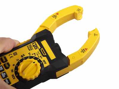 Figure 1: Use of a tong meter.Since copper tends to corrode when exposed to fumes from many processes, the anode hooks need to be cleaned periodically. The easiest way to monitor this is to use a tong (a.k.a., clamp) meter to verify that a given hook is carrying the proper current (Fig. 1). If the reading drops, it’s time to clean the hooks.
The spine of the rack is also most often made of copper to allow for the even distribution of current through all rack tips. A typical spine is made of 1/4 × 3/4” or 1/4 × 1” copper, which can carry 200 to 250A, respectively. Corners of the spine should be rounded to allow full coverage of the PVC, as sharp corners are coated with a thinner PVC layer.
All bare metal, with the exception of the hook and rack tips, needs to be coated, typically flexible PVC (trade name Plastisol). This plastic needs to be thick enough to withstand normal handling, which may include impact with the shop floor (when the rack is dropped or it crashes into a tank lip during a malfunction in the automatic plating line).
While PVC is an excellent rack coating, it has its limitations. Exposure to sunlight during outdoor storage can make PVC brittle. Repeated exposure to strong oxidizing solutions such as concentrated nitric acid will eventually reduce the flexibility and make the plastic more prone to cracking upon impact. Even with the best care, the plastic tends to become rigid with use and may split. Any splits in the PVC can cross-contaminate processing solutions which can lead to severe plating problems. Racks need to be inspected, and those with PVC damage need to be taken out of service and sent for repair. Do not give in to the temptation to use damaged racks!
Rack tips must be made of a material that will withstand the chemicals that the rack will be exposed to while, at the same time, allowing current to flow between the rack spine and the part. A typical tip may carry as much as 10A of current.
The most common material used for rack tips in electroplating is stainless steel.
Rack tips use either gravity or spring loading to maintain electrical contact between the rack, and the part mounted on the rack. Gravity load rack tips may be used on parts that are heavy enough to maintain electrical contact when the plating solution is not sensitive to current interruptions or fluctuations (e.g., cyanide-based plating solutions, electroless plating solutions) and in cases where the solution is not vigorously agitated. Parts that are lightweight and/or have flat surfaces and are loaded on gravity hooks may float off when the rack enters the solution from the “push” of the liquid during entry. Hooks that have a 270° curve perform better at holding parts in place than “V” hooks. In some cases, the entry speed needs to be adjusted.
Spring-loaded rack tips hold the parts in place by the application of a constant force originating from a coiled spring rack tip or a set of hardened rack tips that pinch the part. Examples where spring-loaded contacts are used include decorative nickel-chromium plating and anodizing because current interruptions in these processes result in rejects. Rack tips used for spring loading need to be resistant to fatigue, as loading and unloading will subject the tip to repeated flexing. Sharp bends in the tips need to be eliminated as these will fail by fatigue over time.
The most common material used for rack tips in electroplating is stainless steel. In applications where current carrying capacity is an issue, bronze may be used, but bronze is quickly attacked by mineral acids, so its use is very limited. In applications where tips must be even more inert than stainless, Monel may be employed. Titanium tips (and racks) are most often employed in anodizing operations.
As previously emphasized, rack tips need to be kept clean and free of metal build-up. Inspection of rack tips after stripping should weed out racks with tips that are not completely stripped. Any residues that remain typically are far lower in conductivity than the clean metal. Parts that are racked on tips that have residual metal salts will be plated at a lower-than-desired current density. In some cases, poor rack contact will cause a large area of misplate (rack marks) at the contact point.
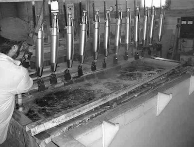 Figure 2: Racking of hollow parts showing plugged ends and weights.Parts may be loaded on a rack “back-to-back” to increase productivity. In such cases, the rack should be designed to stagger the parts so that the part in front does not shield the part in the back.
Parts with recesses or pockets pose a special racking problem. In one orientation (cup facing upwards), the cup drags out too much liquid. In the other (cup facing downwards), the part traps gases and air, yielding no plating on the inside of the cup. The best compromise typically results in cup-shaped parts being racked vertically.
On automated lines, racks need to be held in place to minimize rack sway. Depending on the type of parts and connection between racks and shoes on the automated machine, sway can be severe enough to cause a “crash” between a swaying rack and the lip of a tank. When entire racks of parts may move during processing, and firm electrical connections must be maintained, thumb screws may be installed on the rack hook to obtain stability.
Hollow parts, such as the motorcycle mufflers shown in Fig. 2, will tend to float when introduced into any liquid. The plater of these parts solved two problems. The tendency of these hollow parts to drag enormous amounts of solution during withdrawal was solved by plugging both ends. The resulting tendency for the part to float was eliminated by the addition of heavy PVC-coated weights.
4. Part spacing on racks
 Figure 3: Rack spacing guidance.The rack needs to be designed to space properly the parts to be plated. Parts that are too close together will rob current from each other, yielding “lopsided” plating. Parts that are too far apart impact productivity. When plating in solutions that offer poor throwing power, such as nickel-chromium, parts need to be spaced further apart, and shielding may need to be employed. Parts with difficult geometries or parts that are extremely valuable may need to be plated one at a time with auxiliary anodes, robbers, or shields. In general, racked parts should be equidistant between tank anodes. When there is more than one part on a rack, the spacing of the parts becomes important. Sufficient space must be provided between parts to avoid shading one by another.
The Belke Corporation has developed formulas for determining minimum rack spacing, as shown in Fig. 4. In chromium plating, deposit distribution can be a major problem. No metal will be deposited at too low current densities. Therefore, providing adequate spacing between the parts or using conforming/auxiliary anodes is very important. Note that when you use the Belke formulas for nickel or chromium, the answers obtained for spacing must be multiplied by 1.5 and 2, respectively.
5. Compensating for complex part geometries
When designing a racking system for a given part, we need to be aware of current distribution factors. The current distribution of plated parts is influenced by part contour, racking style, part spacing, shielding methods used, and the use of auxiliary or bipolar anodes.
One of the simplest means of improving coverage in the low current density areas, and decreasing the danger of burning in the high current density areas, is to place a non-conductive (usually plastic) shield (sometimes called a baffle) between the anodes and the high current density area of the part to be plated. The size, location, orientation, and shape of shields are typically determined by trial and error, although scale drawings can assist in measuring distances between various spots on a part and the nearest anodic surface.
For plating complex shapes more uniformly on automated lines, where making contact with auxiliary anodes is not possible, bipolar anodes may be viable. A bipolar anode is not connected electrically to either the anode or cathode. By placing an insulation-covered, highly conductive metal such as copper near an electrified anode, a negative charge is induced in the copper near the anode, and a positive charge is induced at the other end, which is typically made of non-insulated anode material. The anode material is typically configured to follow the contour of the part. A bipolar anode can produce improved deposit distribution in a deep recess, but the degree of control is not as precise as it is with an auxiliary anode, which is similarly constructed but hard-wired to the anode bus.
Single, large parts that are racked and pose geometry problems may benefit from the addition of a “thief” or “robber” to draw current away from high current density surfaces. The robber is typically a wire or rod that “competes” for current in areas that have an excessively high current density. By splitting this high amount of current between the conductive robber and the part nearby, the current density on the surface of the part is at a manageable level.