Dummying is the plating industry jargon for electrochemical purification.
 Eric Svenson Sr.It is widely used in nickel, copper, and zinc baths to remove tramp metal contaminants at low current density, frequently on a corrugated sheet cathode. Dummying is also a very useful technique to remove certain impurities from a hexavalent chrome bath but in a very different way.
Unfortunately, some chrome platers are not aware of the best techniques to use when dummying their bath(s) because there is a lot of misinformation about it.
The purpose of this article is to help chrome platers better understand the dummying process, improve their overall efficiency and lower their costs.
What Dummying Removes
Dummying a hex-chrome bath is a very useful way to remove excess trivalent chrome and chloride. Contrary to what some believe, dummying does not remove metallic impurities like iron and copper.
These metal ions do not plate out of the chrome bath and are best controlled by decanting the bath to maintain the Total Contaminant Level (TCL) within the range of 4.8 – 7.2. TCL is simply the sum of the trivalent percent plus the grams/liter of iron and copper.
What Causes These Impurities?
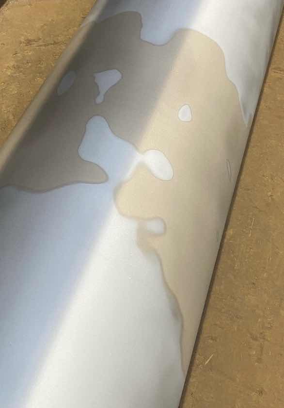 Result of 7% trivalent chrome with total contamination of 12.10.Trivalent chrome is constantly generated at the cathode surface during plating as part of the electrochemical reaction of the chromic acid solution. The ideal trivalent concentration is 1%, and it becomes problematic much above a 2.5% - 3% level. A well-designed system automatically converts this trivalent back to the hexavalent state to maintain the ideal 1% level. This conversion is controlled by the anode: cathode area ratio.
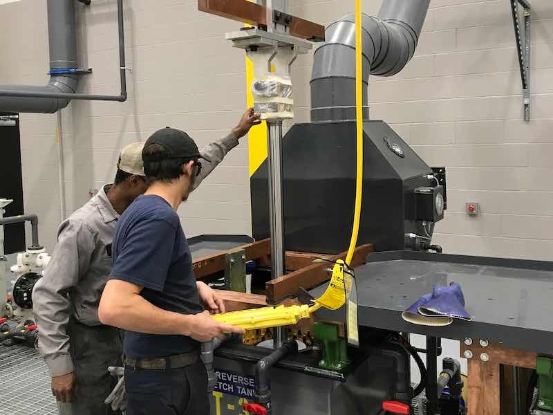
However, excess trivalent chrome is formed when reverse etching in the plating bath, from using steel anodes, whenever a foreign metal is dissolved, from some fume suppressants, and when oil, grease, or any organic item is introduced. It also increases when the plating anode: cathode area is less than a 1:1 ratio, with up to 2:1 being optimum. Whenever these conditions exist, the trivalent builds at a faster rate than the ideal 1% level can be maintained. However, excess anode area should be avoided because at a 3:1 ratio, the anodes tend to form scale and warp, and at a 4:1 ratio, these problems become magnified.
Operations that plate mostly OD work have the ideal anode area and use the proper techniques rarely have trivalent issues. However, ID operations always generate excessive trivalent because the anode area is much smaller than the cathode, and, therefore, the trivalent generated does not get converted back to the hexavalent state. The problem with ID plating is made worse for operations that use anodes that are not lead alloy, such as platinized titanium or MMO anodes.
High trivalent levels reduce the bath’s tolerance to iron and copper impurities, cause slower plating speeds, and reduces the bath’s conductivity which greatly increases the electrical costs because of the higher wattage required.
High trivalent levels are a problem many hard chrome platers face today, but it can be easily controlled using the recommended dummying procedure.
Chloride is typically introduced into the chrome bath by drag-in from:
- a hydrochloric acid stripper
- a chlorinated solvent
- a prior nickel bath, or
- from the water supply
The chloride concentration should be controlled below 20 ppm as the ideal level.
Excess trivalent and/or chloride cause other plating problems besides slow deposition rates. This also causes pitting, deposit burning, poor throwing power & coverage, roughness, dullness, hazy/gray deposits, skip plating, softness, poor adhesion, and macro-cracking.
High chloride levels also increase the trivalent build-up rate because it deactivates the lead peroxide anode surface.
Anode Ratio
Dummying is most effective using a large anode area and a small cathode area. The recommended area ratio is 30:1, but anything over 20:1 works efficiently. Using a lower ratio increases the required dummying time, and therefore the cost, by a significant amount.
Calculate the surface areas by multiplying π (pi - 3.1416) x the diameter x the length. As an example, an anode that is 10” in diameter x 60” long under solution would have a surface area of 1,885 square inches. If a 0.5” diameter x 60” long cathode was used in this, it would have a surface area of 94 square inches. The ratio for this configuration would then be 20:1
Getting to a 30:1 ratio with this set-up would require a 15” diameter anode when using a 0.50” cathode rod. This helps illustrate how much more anode area vs. the cathode area is required for an efficient dummy treatment.
The best anode type to use is a large diameter round conforming anode to provide the needed surface area. When round stick-type tank anodes are used, only include the active anodes that are passing current to the dummy rods and only calculate the surface area that faces the dummy rod, i.e., not the back side that is away from the dummy rods.
When doing this math for a three-buss bar system, you will discover that it is almost impossible to get much higher than a 5:1 ratio, where a 20-30:1 ratio is best. For this reason, we do not recommend using round stick-type tank anodes for dummying treatments. If these must be used, you will experience a much longer dummying time and drastically higher electrical costs because of the low ratio and the inefficiency this causes. Instead of using stick anodes, it is best to use a special dummy cell that is properly sized for the operation. More than one dummy cell may be needed for larger tanks.
Dummy Cell Design
The cost of a special dummy cell will be quickly offset by a drastically shortened dummy time, much lower electrical costs, and a quality improvement of the chrome deposits. A 24” dummy anode using a 1” cathode rod would have a ratio of 24:1 and 32:1 if a 0.75” diameter cathode rod was used. Either of these sizes would be a good choice, with a preference towards using the 0.75” rod.
The ideal cell anode is made from cast mesh lead alloy #5540, which contains both tin and antimony, either 0.25” or 0.50” thick, depending upon the length and the current that will be used. The mesh design contains the desired open areas for gas escape, which also creates higher current densities along the edges of the openings.
The cathode is a small-diameter steel alloy rod that is about 1” above the anode’s bottom. A 0.25” thick CPVC disc is attached to its bottom to keep it in the center and prevent arching. The top should be open for gas to escape easily.
The dummy rod will receive a considerable chrome deposit and should be cleaned of its nodulization fairly frequently and replaced with a new rod after it becomes too thick. Both the anode and the center rod are connected to the tank’s bussing in the normal way using copper bars; these would have an insulator on one end for a two-buss-bar system and a center fixture for the cathode rod in a three-buss-bar system. The dummy cells can either be made in-house or engineered and fabricated.
Operations with ongoing trivalent problems should use an extra bath that is rotated out of production into a separate purification tank so the plating can continue in the production tank. The bath(s) are rotated whenever the trivalent reaches their set upper limit, which is typically around 3%.
Increasing Dummy Efficiency
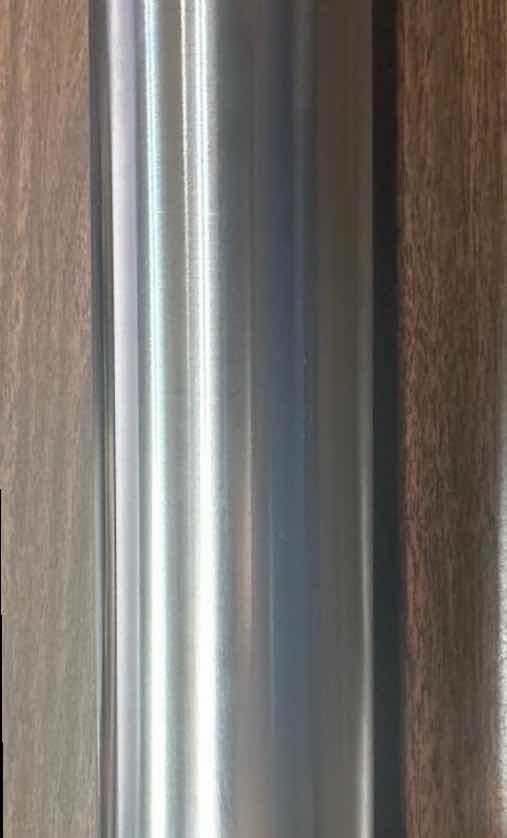 Result of Cr-3 reducer and effective dummying in a 4,000 gallon tank salvaged.Many hard chrome platers have discovered that adding 1.5% by volume of CR-3 Reducer before dummying significantly increases the purification efficiency and reduces the overall dummying time required as well as the cost. Maintenance additions are not needed for dummying times up to 24 hours.
See below for maintaining the CR-3 Reducer when longer dummy times are needed.
Treatment Time
When CR-3 Reducer is used, and the bath is dummied using the proper conditions, including the 30:1 ratio, the removal rate is 2% trivalent and 50 ppm chloride per 12 hours. A 20:1 ratio requires 1.5 x more time, a 15:1 ratio requires 2 x more time, etc. Lower impurity levels are reduced at a slower rate than high levels are. Dummying trivalent from 3% to 1% takes longer than from 5% to 3% does, even though both are a 2% reduction.
The factors that increase the dummying efficiency and lower the time required are:
- using as high a ratio (up to 30:1) as possible,
- using as high a current as the dummy cell can stand without overheating,
- using as high a bath temperature as the tank lining can stand (140°F -145°F is best),
- using vigorous bath agitation, and
- maintaining the CR-3 Reducer level at 1.5%.
Dummy Operation
The following dummying procedure is recommended regardless of the tank bussing, fixturing, or anoding set-ups; the principles are the same. This procedure using the ideal ratio is something like 1,000 times more efficient than using porous pots, and it avoids having to remove and dispose of the green sludge the porous pots generate. Sludge is not generated when using a dummy cell.
- Add 1.5% by volume of CR-3 Reducer to the bath just prior to dummying. This greatly increases the treatment efficiency and reduces the time required. CR-3 Reducer will not harm the bath and is consumed during the dummying process. However, CR-3 Reducer should not be used in high-fluoride baths like Dura-100. For extended treatments, maintain this by adding 1/2 gallon of CR-3 Reducer for every 100,000-ampere hours spent dummying.
- Use as large of an anode area as possible. It’s best to use as close to a 30:1 ratio (active anode: cathode surface area) as possible. A 30:1 ratio is sometimes difficult to achieve, but it should be at least 15:1. Use the longest anodes and cathodes the tank will allow.
- The cathodes used are frequently 0.50” - 0.75” diameter steel rods. These cathodes will build up with a heavy chrome deposit while dummying, typically forming loose trees and nodules. Prior polishing of the dummy rods will reduce this nodulization. It’s important to occasionally remove these from the dummy cell and remove the chrome trees as they can, depending on the spacing, short out the cell and possibly damage the rectifier. The dummy cathodes are changed to fresh ones when the chrome build-up becomes excessive.
- Use as high a bath temperature as the tank lining will handle; 140°f - 145°F is ideal.
- Use as high a current as possible without overheating the cathode or bussing. If possible, a cathodic current density of 6 - 10 ASI is best. If this is not possible without overheating, then use as much current as the set-up will allow.
- Use as much bath agitation as possible. This ensures sufficient anode surface contact with the entire volume of the bath during the treatment.
- Periodically check the anode surfaces to be sure they are active, are not scaled, and have the desired brown-black color. Yellow anodes indicate no or very low electrical flow, usually from poor contacts. An active anode surface is needed for converting the trivalent back to the hexavalent state. Clean the anodes, if needed, with AnoBest 104 to keep them active.
Dummying in an empty area of the tank is OK even when plating other parts; you just can’t use as high a current. It’s also OK to dummy at night or over weekends; just be sure to check the process periodically to be sure that everything is working well and the bath doesn’t need a water addition to replace evaporation.
Reducing Electrical Costs
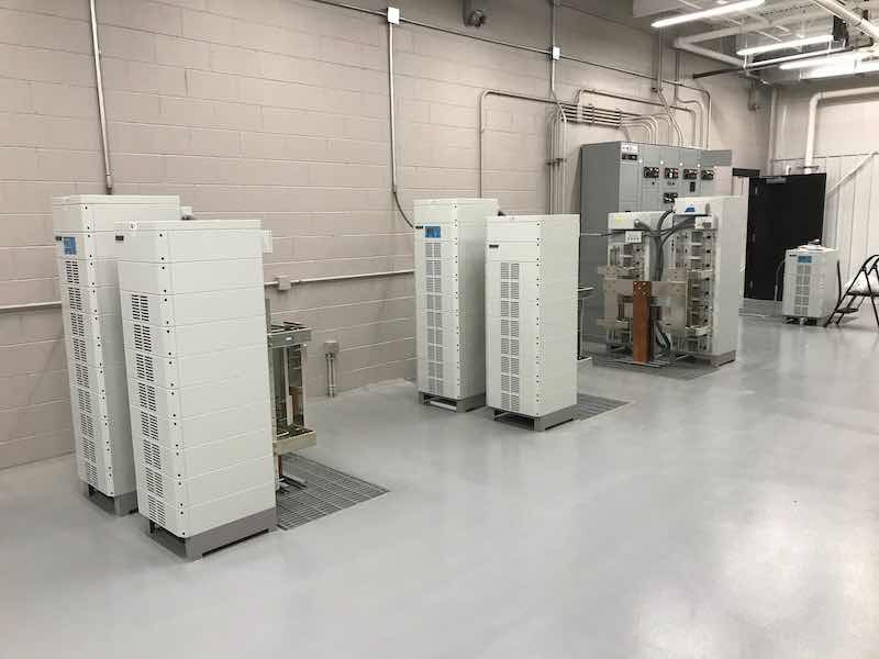 Switch Mode Rectifiers.As mentioned earlier, high trivalent levels significantly lower the bath conductivity by adding unneeded resistance. This requires a higher plating voltage to maintain the same current density.
The electricity is sold in kilowatt-hours (KWH) units which for the plating rectifier is DC volts x amperes x the hours used divided by 1,000.
A bath that is high in trivalent could increase the DC voltage requirement by an additional 6 volts (from 6 to 12 DCV), thusly doubling the watts consumed. Doubling the watts equates to doubling the rectifier's electrical cost for every hour of plating. Many complain about their electrical bill, but few realize why.
Take, for example, the extra cost for a shop plating 8 hours/day, 250 days/year at 10,000 amperes. The 6-volt difference x 8 x 250 x 10,000 equals an additional 120,000 kWh per year. If their electrical cost was $0.18/KWH, this would amount to an additional $21,600/year spent due to operating with high trivalent levels. Actually, this amount is minuscule compared to the production lost from slower plating speeds and the increased rework rate. Those issues could easily increase this unneeded operational cost by more than 10X.
Anode Activation
Dummying is also used for anode activation, but in a different way because a dummy cell isn’t used. As stated earlier, the plating anodes need the lead peroxide film, which has a chocolate brown-black color. Idle anodes that stay unused in the tank overnight lose this film and form a yellowish lead chromate film. These anodes should be activated before starting to plate parts by dummying them with steel cathode rods that are the same length as the anodes.
This type of dummying converts the yellow film back to the desired chocolate brown-black color for the best anode activation and plating results.
Typically, 1” -2” diameter rods are used at a current density of 3-4 ASI for at least 10 minutes and spaced so all the anodes get current. This should be repeated at the beginning of production whenever the anodes have been idle.
Eric Svenson Sr., Master CEF and IUSF, is CEO of Plating Resources, Inc. Please contact the author at Sales@Plating.com with any comments or questions on this information. Visit www.Plating.com