The behaviors of the Zinc coating would be subjected to the complex zinc anion and also the additives, current densities, and compositions of an electroplating bath.
In this study, the complex agents (anise aldehyde and Lugalvan P) were added into the electroplating bath to improve the anti-corrosion ability and inhibit the dendritic structure on zinc coating. The Lugalvan P is added into the electroplating bath to inhibit dendritic structure during electroplating. The anise aldehyde and complex zinc ions plate a smooth zinc coating. Moreover, the crystalline structures of zinc coating were analyzed by X-ray diffraction analyzer (XRD), and the surface morphology of zinc coating was observed by the scanning electron microscope (SEM). The results show that the Lugalvan P additive forms the relatively highest flatness, which inhibits the dendritic structure. High electroplating efficiency was achieved with current intensity of 3 A cm-2, and a smoothness and gloss deposited surface could be obtained. With increasing the deposition current density, it can form a better zinc coating with low plating bath resistance to form a higher anti-corrosion zinc plate.
Introduction
Alkaline zinc plating zinc plating industry has always been one of the best options for the rust-preventive metallic iron [1-4], pure zinc and zinc alloy plating to replace the zinc plating has been published [5-7], but pure zinc plating is still the most simple, reliable and high-cost method of corrosion. Because corrosion of zinc coating can be isolated from the outside of the coated surface of the substrate, and also includes a cathodic protection [8].
Galvanized coating technology through research and evolution time, the current can be broadly divided into three types, respectively [9-12] acid zinc chloride, zinc cyanide and a basic alkaline non-cyanide zinc. Wherein cyanide alkaline zinc best effect (smooth, uniform thickness and high and low current region of the low- corrosion equipment), but it contains highly toxic cyanide is the [13-15], wastewater treatment cost is quite high, it is now have no acid zinc cyanide and technological development toward the basic, but its coverage (covering power) and deposition efficiency is still alkali cyanide and zinc [16,17].
Although acid zinc plating bath contains no toxic substances, but still faces two kinds of problems [18]:
- When plating system plating bath of an aqueous zinc cathode surface adsorption and hydrogen generation is easily formed, resulting in decreased current efficiency, but also results in the zinc coating unevenness.
- High current density zinc plating (High Current Density; HCD) accompanied by poor surface morphology and crystallinity.
Hull cell tank test at high current zinc-plated tip member, can easily form a dendritic zinc deposition [4], uneven coating thickness, since the adhesion of dendritic zinc layer deposited easy tear off in subsequent processing.
The HCD process is anticipated for the industry, because it can increase productivity with minimal cost. Conventional acidic galvanizing bath containing zinc salts (zinc sulfate or zinc chloride), buffers, or to improve the conductivity of the salt (chloride or sulfate) as well as other organic additives to improve coating coverage, covering power ( throwing power), roughness, brightness, corrosion resistance, physical and chemical properties.
Although alkaline zinc cyanide can easily get intact zinc coating [19], however, its toxicity is too high. It could be obtained efficiency electroplating by the acid zinc electroplating process, but high corrosion equipment of plating bath as well as the poor plating coverage limited the applications [20,21]. Therefore, alkaline non-cyanide zinc plating efficiency although it is not high (only about 30 to 35% of zinc cyanide) [21], but with high covering power coating, and a low device resistance. Taking these various perspectives, the ability to improve the alkaline cyanide-free zinc, and industrial application can be extensively used.
Alkaline zinc plating bath consists essentially of zinc ions, excess sodium hydroxide and water. However, in galvanized high alkalinity conditions, if no organic additives, the resulting zinc deposition is rather rough and cannot make any use of applications [19].
Generally, it contains a series of organic ammonium compound additives in the electrolytic solution in the industry to obtain bright coating with a smooth surface [21]. These additives have been identified as a leveling agent (Levelers) and brighteners (brighteners) in the plating bath. By these additives, it may inhibit the diffusion of zinc ions to the plating surface of the galvanized overvoltage increased to accelerate the nucleation rate of zinc [20].
Since the galvanized iron metal substrates have excellent anti-corrosion properties, as well as the low built-up cost, easy to operate, it is most widely used for the plating industry. Some problems limited the properties and the current efficiency on the zinc coating, hydrogen is the first problem, since a zinc electrode and the hydrogen generation will lead to the adsorption of the plating process will reduce the current efficiency. Second, the high current in the cathode region of the plating often cause a scorch generation or a dendritic structure, resulting a poor deposited quality. It would easy to fall off the galvanized layer, and the corrosion resistance deteriorates, so how to improve the plating production is motivated.
To overcome the high current electro-galvanized layer, the industry has been plagued by problems. Therefore, this experimentally pure zinc plating for the main process to do a variety of organic additives to improve plating of the cathode, and investigate the electrochemical behavior of these organic additives in an acidic or an alkaline bath with the case of the system performance. Via a linear scan voltammetry (the LSV) to understand the effect of complex organic additive effect on the plating at a high current density, and then additionally by a scanning electron microscope (SEM) and X-ray observation of organic additives on the galvanized surface morphology, growth affect the structure and crystalline characteristics.
Further zinc electrodes are some restrictions on the practical application of zinc on their own characteristics, such as it will generate a dendritic structure of the galvanized zinc alkaline solution.
In this study, the complexing agents anise aldehyde and Lugalvan P were added into the Zinc bath to inhibit the dendritic structure during electroplating. The electrochemical behaviour of the alkaline zinc coating layer would be analyzed and the materials properties would also be examined. The electrochemical analysis of the zinc coating with a linear voltammetry (linear sweep voltammetry, LSV) was to seek deposition potential, Chronopotentiometry discharge method (CP) was to obtain the coating of the discharge efficiency. The crystalline structures of zinc coating would be examined by X-ray diffraction analyzer (XRD) and the surface morphology of zinc coating would observed by the scanning electron microscope (SEM).
Experiment
In this experiment, the groove 267 mL Hull cell container was used for producing a cathode deposit that records the character of electroplate at variant current densities within the operating range. The cathode is electrically galvanized substrates to contact the test negative power.
This experiment is a test strip plating process prior to the same current Hull cell plating bath for one minute, then washed with water, and then subjected to surface pickling (pickling solution is a mixture of nitric acid and deionized water) to remove surface oxides, corrosion the product was then impurities and other contaminants, rinse with water, the same current level in the galvanizing bath 5 minutes out of Hull cell rinse with water, pickled surface (removal of oxide film), then try again with an electric hair drier sheet.
Pickling solution to 485 mL with deionized water and 15 mL of a mixture of nitric acid, nitric acid in the pickling solution are mainly bright surface, and the film dissolved corrosion products and the like.
The DC power supply was be carried out in this study and the anise aldehyde and Lugalvan P additives were be adapted as the complexing agent to inhibit the generation of hydrogen and dendritic structure formation during electroplating. In this experiment, the current densities are galvanized 1 A, 1.5 A, 2 A, 2.5 A, 3 A cm-2, respectively, and the last recorded initial voltage and the voltage at different test strip galvanizing current electrical Harrington groove. These data used to analyze the plating rate in the test strip at different current Hull cell plating solution tank.
Electrochemical analysis linear voltammetry (linear sweep voltammetry, LSV) was used to seek deposition potential, and the Chronopotentiometry discharge method (CP) was used to obtain the coating of the discharge efficiency.
To study the crystalline deposits of plating, the X-ray diffraction analyzer (XRD) was used to analysis the crystalline characteristics and the scanning electron microscope (SEM) was used to observe the surface structure.
Experiments Reaction Principle
When the metal deposition or the like dissolved electrolytic reaction, the amount of electrolysis involving reactants or products with power through proportionally. Faraday's law quantitative description of this relationship:
- When the amount of the electrolytic metal deposition or dissolution and is proportional to the power through
- The quality of different metals deposited by the same amount, is proportional to its equivalent Moore. The number of charges 1mol proton called Faraday constant, is represented by F, F = NA e = 6.023 x 10²³ / mol x 1.60218922 x 10⁻¹⁹C = 96500 C / mol.
Wherein, NA is a constant, e is the proton charge, C is the unit of coulomb electricity. Customary in the industry with "ampere - hours (A •h)" shows the power, 1F = 26.8A•h. Faraday's laws of electrolysis may be expressed as m = I t M / 96500z formula, M and z is the valence of plated metal mass moire metal ion, m is the current I through the elapsed time t after the weight of the metal deposited.
Flowing through the electrolytic cell during electrolysis power can be obtained from various methods, for the most accurate value, it is necessary to use coulomb meter. Coulomb meter is a 100% efficiency of the electrolysis cell, with the test series using the plating bath. Coulomb meter is a typically copper or silver iodide coulomb meter, electricity obtained by weighing the weight of metal electro-winning, iodine coulomb counter it is produced by electrolysis of iodometric titration to determine the amount. The copper coulomb counter is most widely used.
The working electrode substrate was used with industrial purity of 99.95% and a 1cm x 2cm of red copper substrate. Then drilled using a drill hole (orifice 1.2mm pore size) on a copper sheet, copper wire and then welding (at both ends of the enameled paint scraped off the table, while the welding part, the other side is in communication with the power supply, copper about 15cm). The electrode welded using Teflon (PTFE) is wound, showing only the total surface area 2cm X 2cm.
The copper surface treatment of the substrate is first copper electrode in making a goodlye, red copper by electrolytic polishing to make the surface smooth. In this step, the red copper anode is placed in position. Electrolytic solution of 1 M NaOH, through which current is 0.12 amperes, electropolished 5 minutes. After electrolytic polishing, the surface of the electrode with deionized water clean. Wash the electrodes, and then subjected to electrolytic degreasing grease removing the electrode surface. When the copper is subjected to electrolytic degreasing cathode electrode in position. Electrolytic solution of 1 M NaOH solution, the current through the electrodes is 0.3 amps. Electrolytic degreasing for 10 seconds, using the generated hydrogen bubbles away from the electrode surface of the grease.
After completion of electrolytic degreasing, washing with deionized water to a clean electrode. And placed in ultrasonic oscillator shaking cleaning is carried out for 5 minutes, and then pickled to remove the oxide electrode surface, so as to facilitate the activity of the plating is performed. Pickling solution is 1: 1 concentrated sulfuric acid mixed with ultra-pure water dilution. Pickling time is 1 minute. And then subjected to electrolytic degreasing 10 seconds. After completion of pickling electrode surface washed with deionized water, and then shaking using ultrasonic oscillator for 5 minutes.
The electrochemical plating bath analysis linear sweep voltammetry experiments with constant current chronopotentiometry assay. Characteristics of linear sweep voltammetry of the electrode potential over time as a forward scanning or reverse scanning, while the measurement results will be related to the rate or direction of change in the potential of this method is typically performed when the solid electrode used for study [15 ]. Through the action of the linear sweep voltammetry, the scanning speed is controlled at 5 mV /s. The current detection voltage related to the bath at various conditions. Galvanized zinc plating studied under different conditions, the crystal growth of zinc precipitation state using a current efficiency change chronopotentiometry. Structure identified object material composition of the coating itself understanding, microstructure, and other properties, crystalline form, X- ray diffraction experiments (XRD) a crystalline coating is responsible for detection, growth situations plane. A scanning electron microscope (FE-SEM), the surface patterns can be observed, while usually accompanied by EDS, WDS and elemental mapping functions, may be analyzed and the individual elements of the multi- component, trying to understand the composition, surface morphology and distribution of pores.
Experimental Results and Discussion
Acid zinc is generally used as the primary brightener aromatic aldehydes and ketones, but because of its poor water solubility, it is necessary a surfactant or wetting agent to help dissolved and dispersed in the plating bath. Additives acting between these quite complex, these viewpoints, this study will mainly affect the analysis of the current density, the primary brightener and surfactant traits and zinc coating the crystalline structure. Characters crystalline structure of zinc-plated surface, respectively will be X-ray diffraction analyzer for detection by a scanning electron microscope (SEM). Further, linear voltammetry method to understand these complex organic additives influence of electro- galvanized baths.
Ammonium chloride bath main components 22wt% (4.1M) and 6 wt% (0.44M) of zinc chloride, using 1M HCl pH was adjusted to 5.0. And the flow efficiency of the electro-galvanized η (CE) by the equation (1) is obtained:
η (%) = (2w / ZnAW) X 100% / [(I X t) / 96,485] (1)
Wherein, w is a zinc deposit weight, ZnAW zinc molecular weight, I is the current through, t is the elapsed time.
Experimental conditions in the preparation of zinc plating temperature controlled 250 C, pH = 2, during the deposition of zinc ions generally accompanied by generation of hydrogen gas, at this time will be a competitive reaction shown in the following two:
Zn + 2 + 2e- → Zn (2)
2H + + 2e- → H2 (3)
Due to the occurrence of hydrogen can cause the overall current efficiency decreases and the surface of dendritic structure.
 Fig. 1. LSV examination for zinc plating in 1M H2SO4 solution.The technical development of a weakly acidic galvanizing system, many of the organic additives are added to the plating bath is necessary to obtain a broader current density range and bright region richer zinc coating ductility. These foreign additives are grouped into three categories: primary additive, and auxiliary minor additives additive. The general main additive concentration are much higher than the galvanizing bath additives or auxiliary minor additives, which main purpose is to enhance the flatness and dispersibility of the zinc coating bath. Further, the main feature is the additive aqueous chemotactic effect, helping the minor additions (or brightener) was dissolved in the plating bath. While the secondary brightener mainly zinc coating so that light, under certain conditions additionally also help improve the dispersibility of the plating bath. Auxiliary additives are added to the main purpose is to increase the range of light, so that the bath easier to operate, further additives can also help some auxiliary brightener dissolved in the plating bath. Maybe it has a part in the plating bath additives in the role not only one of the above, maybe two or more, especially when excessive dosage, but in any case, in order to control the galvanizing bath, three listed above additives are indispensable.
 Fig. 2. A zinc coting is prepared in the different plating period with (a) 5 min, (b) 10 min and (c) 20 min.This study is plating bath composition of 15wt% (3.75M) of sodium hydroxide and 1.5% (0.18M) of zinc oxide further added polyamines Poly quaternary ammonium salt-Lugalvan P 0.2wt% to completion of the final plating.
The polyethyleneimine has been widely used in the galvanizing bath alkali cyanide, which can effectively improve the dispersion capacity and coverage of the plating bath at low current density, but also part of the glittering effect. Further, ethyleneimine in alkaline zinc- nickel alloy plating bath is also very good complexing agent.
Lugalvan P alkaline cyanide zinc bath at a high current density effective additive. Galvanizing bath of substantially 15wt% 1.5wt% sodium hydroxide and zinc oxide are consisting of high current density (100mA cm- 2). In the absence of any additives added condition that the deposition of zinc can be seen clearly only a very rough surface.
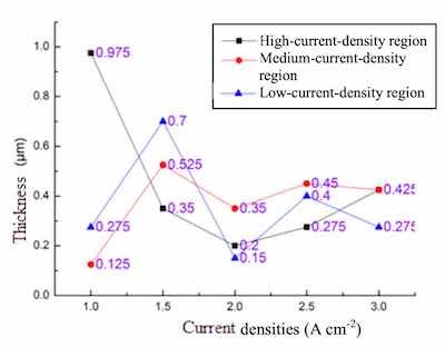 Fig. 3. Relative solution resistance of the Zinc coatings in accordance with current densites during 5 mins.Figure 1 shows the alkaline zinc coating in the 1M sulfuric acid by the Line Scan voltammetry (LSV) detection, scanning potential range from -2V scan to 3V, scanning rate of 1mV s-1, 1 M sulfuric acid in this experiment is mainly used to test alkaline zinc coating. Accordingly, the open circuit potential of the alkaline zinc coating is -0.8V, and the passivation region is between 0.2 and 0.8V with an etching current density of about 0.0001 A cm-2 when the corrosion potential is adjusted from 1V to 3V. Moreover, the corrosion current density increases by ten times to 0.001A cm-2. Hence, it could be judged that the corrosion potential is more than 1V, the surface structure of the alkaline zinc coating began to loosen. When the corrosion potential increased up to 3 V, the structure is damaged by ten times the speed. According to the Fig.1 result, the alkaline zinc coating is strong enough to protect sulfuric acid.
The anti-corrosion ability of a zinc coating is affected by a combination of characteristics, including current density, and additives. In this study, the zinc coatings were prepared in the different plating period with (a) 5 min, (b) 10 min and (c) 20 min during a plating process with different plating period. The anti- corrosion abilities of those oxide coatings were examined in a 5 wt.% NaCl solution for the potentiodynamic polarization test. In addition, the polarization curves of the oxide coatings are shown in Fig. 2.
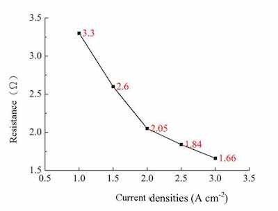 Fig. 4. Relative thickness of the Zinc coatings in accordance with current densites during 5 mins.The zinc coating in the electrolyte with additive contained a passive potential range from -1800 to -1200 mV (see curve c with 20 min period). Moreover, the corrosion current density of the coated metal in the electrolyte with additive was 1.2 × 10⁻⁶ A/cm2. Accordingly, the right additive can structure a dense, uniform, thick, and high crystalline zinc coating on substrate.
Figure 3 presented the impedance of the bath resistance of an alkaline zinc plating at different current densities. With the increase in current from 1A cm-2 to 3A cm-2, the resistance is reduced from 3.3 ohms to 1.6 ohms. The overall electroplating solution becomes low impedance, which is due to Lugalvan P complexing agent at a low density of zinc ions active malocclusion before alkali zinc plating solution, and when the working electrodes as the current density increases, the adsorption of wrong engagement Lugalvan P zinc ions and the like are also fold increase in the rate of release, can be seen Lugalvan P suitable for alkaline zinc plating bath known as leveling agent.
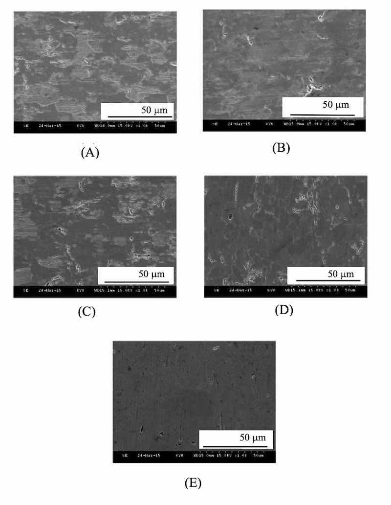 Fig. 5. The SEM morphologies of Zinc coatings are prepared at different current densities of (A) 1, (B) 1.5, (C) 2, (D) 2.5 and (E) 3 A cm-2 at high-density region.Figure 4 shows the impedance of the zinc plating thickness at different current densities. The data presented in the study were deposited in an alkaline bath with different current densities of 1, 1.5, 2, 2.5, and 3A cm-2 in a Hull cell. The data found by the Hatschek test, the current position at a high current density areas tend to be stable uniform thickness of 0.3 ~ 0.4 m. Thus, the Lugalvan P complexing agent system acts as an effective smooth zinc coating having a consistent performance.
The SEM images (Fig. 5) show the surface morphology of the high-conductivity zone of the Hull Cell substrate at different current densities of 1 A, 1.5 A, 2 A, 2.5 A and 3 A. The brightness corresponds to the different current density formed on the Hull Cell sheet. With Lugalvan P addition, high-conductivity zone of the zinc coating cathodes exhibit excellent brightness at high current density of 3A. The uneven pores are relatively smaller and less.
The surface morphology images of the alkaline zinc plating of the medium-conductivity zone of the Hull Cell substrate at different current densities are shown in Fig. 6. It is found that the flatness of the plating surface is the worst, and it is clear that there are a large number of uneven pores formed. As the current densities increases to an relatively high of 2.5A and 3 A, better flatness of zinc coating surfaces could be obtained, as sown in Fig. 6(D) and 6(E), respectively. However, compared with the surface flatness at the high- conductivity zone, the pores are unfortunately larger in the medium-conductivity zone at the same current densities.
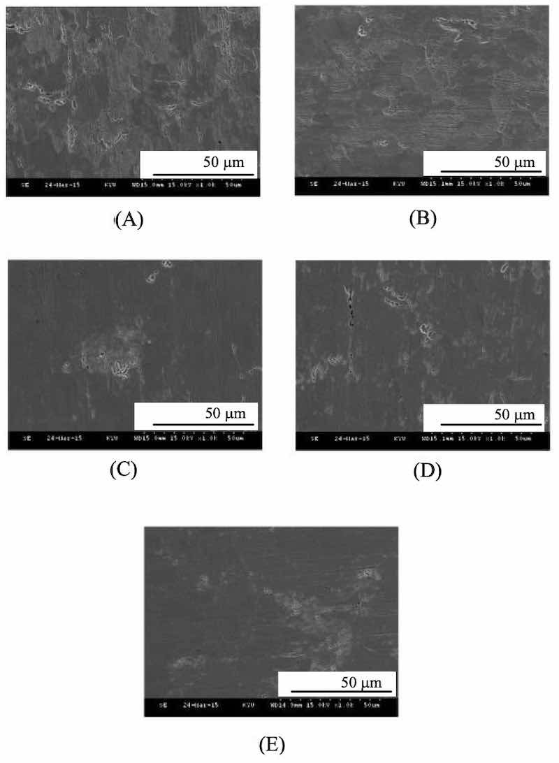 Fig. 6. The SEM morphologies of Zinc coatings are prepared at different current densities of (A) 1, (B) 1.5, (C) 2,Figure 7 shows basic zinc coated surface morphology at low-conductive region of the Hatschek sheets at different current densities. It was found that Lugalvan P plating solution in alkaline systems, flatness at the low density region behave of poor conductivity. The existing large pores were highly appeared, resulted the uneven surface.
A smoothness and gloss deposited surface could be obtained at a high electroplating efficiency of current intensity of 3A (in Fig. 5(E)) of the high-conductivity zone of the Hull Cell substrate. The higher the charge density of the additive, the physical stability adsorbing electrode, is formed. The Lugalvan P additive forms the relatively highest flatness, which inhibited the dendritic structure.
Figure 8 shows the X-ray diffraction results at high- current zone, medium-current zone and low-current zone of the zinc coating of current intensity of 3A during 5 mins. The mainly Fe (110), Zn (101), and Fe (200) peaks are appeared, and no other crystal phases were found. The anisaldehyde and the zinc ions complexes effectively, inhibiting the other crystal phases formatted during electroplating.
The results show that the type of complexing agent will be affected with the plating pattern to the coating surface morphology and crystal lattice arrangement, the anodic dissolution behaviour of the zinc coating by the addition of zinc salt anion and the effect of additives, but also by the current density and the plating pattern influences. Thus, an additive to Lugivam P having a higher flatness, and suppression of hydrogen generation with a dendritic structure of the plating.
Conclusions
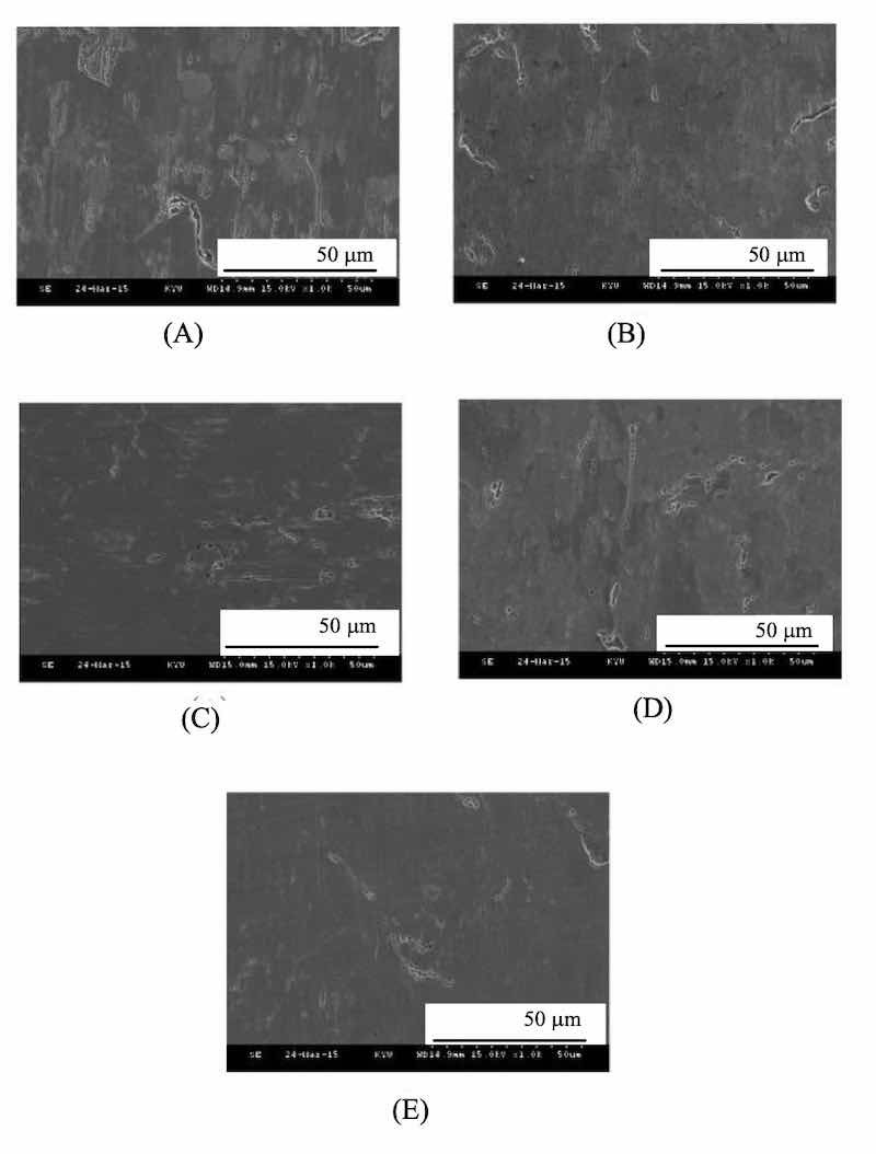 Fig. 7. The SEM morphologies of Zinc coatings are prepared at different current densities of (A) 1, (B) 1.5, (C) 2, (D) 2.5 and (E) 3 A cm-2 at high-density region.Polymeric additives are strongly affected the galvanized zinc coating quality. The higher the charge density of the additive, the physical stability adsorbing electrode is formed. Such that steric hindrance phenomenon in suppressing zinc coating unevenness is generated. After testing, the optimal current density was found of 3A cm-2, which could perform a relatively high plating efficiency to obtain a dense and smooth plating surface.
When quaternized Pyridine carboxylic acid inner salt is added to the system containing Lugalvan P, the original granular form zinc aggregates may be planarized. Thereby that between the quaternized polyamines has a strong additive effect of the addition of zinc alkaline cyanide bath, can effectively improve the flatness and grain boundary structure of the zinc coating.
Authors
Written by Allen Bai1, Kai-Lin Yang2, Hao-Long Chen2, Yu-hong Hong2, and Shyue-Bin Chang3
1: Department of Green energy Science and Technology, Kao-Yuan University, Kaohsiung, 821, Taiwan R.O. C.; 2: Department of Electronics Engineering, Kao Yuan University, Kaohsiung, 821, Taiwan R.O. C.; 3: Department of Mechanical & Automation Engineering, Kao-Yuan University, Kaohsiung, 821, Taiwan R.O. C.
 Fig. 8. The XRD pattens of Zinc coatings at different current densities (1, 1.5, 2, 2.5, and 3A cm-2) during 5 mins deposited at (a) high-current zone at (b) medium-current zone and (c) low-current zone.References
- Ramanauskas, Appl. Surf. Sci., 153, 53 (1999)
- Kim, B.N. Popov, K.S. Chen, Corros. Sci., 45, 1505 (2003)
- Veeraraghavan, B. Haran, S. Prabhu, B. Popov, J. Electrochem. Soc., 150, B131 (2003).
- M. Martyak, J. E. McCaskie, U.S. Pat. 6585812 (2003)
- Albalat, E. Gomez, C. Muller, J. Pregonas, M. Sarret, E. Valles, J. Appl. Electrochem., 20, 635 (1990)
- Fratesi, G. Roventi, J. Appl. Electrochem., 22, 657 (1992)
- Barcelo, J. Garcia, M. Sarret, C. Müller, J. Pregonas, J. Appl. Electrochem., 26, 1249 (1994)
- M. Martyak, J. E. McCaskie, U.S. Pat. 5718818 (1998)
- Passal, U.S. Pat. 4014761 (1977)
- E. Rosenberg, U.S. Pat. 4251331 (1981)
- W. Skimin, U.S. Pat. 4405413 (1983)
- D. Fellman, H. L. Kaufman, U.S. Pat. 4218292 (1980)
- W. McFarland, U.S. Pat. 4146442 (1979)
- Glaser, W. Streit, R. Fikentscher, G. Gotsmann, U.S. Pat. 4178217 (1979)
- V. Bishop, U.S. Pat. 4210500 (1980).
- K. Lowery, T. W. Starinshak, U.S. Pat. 4229268(1980)
- J. Lash, R. W. Herr, U.S. Pat. 4366036(1982)
- Steinecker,U.S. Pat. 4444630(1984)
- J. Willis, N. Royalton,U.S Pat. 4730022(1988)
- D. Fellman, H.L. Kaufman, U.S. Pat. 4218292(1980)
- Muiller, M. Sarret, M. Benballa, J. of Electroanal. Chem., 519, 85 (2002)