Almost all surface finishes cause some dimensional change, however small, to the part being finished.
 Milt Stevenson Jr.Many coatings even result in a significant buildup that should ideally be considered while the part is being designed. Typically, though, metal finishers and machinists are concerned with controlling the dimensions of existing parts on which design changes are impossible.
What at first looks like a “simple” plating job can entail complicated considerations involving electricity, chemistry, and physics, which may require special processing steps.
On the other hand, with the right preliminary information and the right testing, half the plater’s problems are solved. While plating thicknesses are sometimes difficult to predict, after trial runs and process adjustments, they can be duplicated quite accurately.
If the part’s design cannot be changed—and it usually can’t—it often falls to the plater to ensure that the final dimensions are maintained.
An Electroplater’s Formula
A basic formula of electroplating states that the amount of plating deposited is proportional to the amount of electricity that passes from the anode to the part. In other words, plating thickness is directly related to amps and time, or “amp-minutes.” (The power company figures your monthly electricity bill based on the number of amp-minutes registered on your meter.)
For example, say a part is plated at 10 amps for 10 minutes (100 amp-minutes), and the resulting coating is 0.0002 in. thick, but a 0.0003 in. minimum is required. According to the basic formula, increasing the amp-minutes from 100 to 150 — increasing them by half — will generate the required additional thickness.
So thickness and amp-minutes have a predictable, proportional relation to one another — in theory. Remember that this formula is a guideline. As such, it’s far from being reliable as a technical measurement.
Variations, Variables
Two common plating baths conform neatly to the values of the basic formula: acid copper sulfate and silver cyanide. With these solutions, increases in thickness are proportional to increases in amp-minutes. Both solutions plate very efficiently, nearly 100 percent of the formula’s predictions.
But some baths — conventional hard chrome, for instance — may plate less than 20% efficiency. Such baths can require increases in amp-minutes vastly different from what the formula would suggest. Here, your plater’s experience and technical knowledge are the best guides in estimating how a particular coating will affect dimensions. Especially on unusual coatings, we advise trial runs that include careful, sophisticated thickness testing.
Every plating solution also has a characteristic “current density” range that will affect results. Current density is usually expressed as amps per square foot—the number of amps applied to a part divided by the part’s exposed surface area.
If the current density is too high, parts can burn, and deposits may be powdery, dull, or frosty. But if the current density is too low, the coating can still be dull, or a coating may never form. Current densities vary from two or three amps per square foot for many gold baths to several hundred amps per square foot for hard chrome.
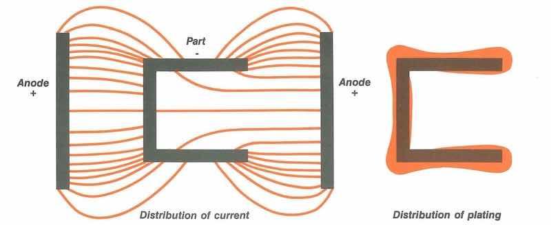 Figure 1: Flow of electrical current concentrates at protrusions and sharp edges. In these “high current-density areas,” plating deposits are thicker. The thickness of deposits is exaggerated for illustration purposes.
Effects of Current Distribution
While overall current density ‘ is measurable, current distribution is much harder to predict. Electricity travels the path of least resistance, so the current distribution over a part’s full surface is rarely uniform (see Figure 1).
Depending on the shape of the part, the racking method, the anode configuration, and the distance between the anode and the part, the current density may be ten times greater at one point than another. Consequently, plating thicknesses are affected.
The thickest deposits (due to high current density) often occur at the bottom-most point of a part closest to the anode. Thin deposits (due to low current density) occur mostly on interior surfaces, typically inside corners and grooves. Controlled thickness is also difficult to achieve in blind holes and on the inside surfaces of long cylinders.
Uneven current distribution, then, is often a real problem. Yet, with certain baths, it can become an advantage. In most cyanide solutions — zinc, copper, and cadmium, for instance — plating efficiency rises at points where the current density drops, usually at inside corners and recesses. Such areas receive a lower current density, so plating there is more effective, allowing coverage to occur in places where it otherwise would not.
Because they provide coverage, however thin, in these normally hard-to-reach places, cyanide baths are said to have good “throwing power.” Baths with “poor throw,” such as bright nickel and chrome, will cover less thoroughly.
Robbers, Dummies, Thieves
How, then, does the plater control uneven plating buildup? He can only minimize it.
First, the plater can shield the high-current areas. The shields — often called robbers, dummies, or thieves — may be conductive or nonconductive, but generally, they either accept some excess current or block its flow.
A second approach might be to raise the current in low current-density areas through an extra anode. In the case of the part shown in Figure 1, the plater might place an additional anode “inside” the part, thereby boosting the current flow. More current will then reach the interior surfaces, helping to coat them more uniformly.
Often, for interior surfaces where a minimum thickness is specified, we will isolate all the exterior anodes and use interior anodes exclusively for at least part of the plating cycle.
Studs, Holes, and Problem Parts
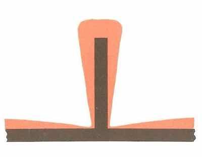 Figure 2: Stud protruding from sheet metal receives uneven plating buildup. Plating deposits are exaggerated.Sheet metal assemblies with protruding studs cause just as many headaches as parts with recessed surfaces. Anyone who has dealt with chrome plating knows that the ends of electroplated shafts are subject to much greater build-up than the center of the shaft is. Similarly, the end of a protruding stud — like most “high current-density areas” — will receive thicker deposits than the areas around it.
A stud can cause secondary problems, too, because the part that anchors it often shields it, reducing the amount of plating at the stud’s base (see Figure 2). To compensate, the finisher might have to plate the assembly until the studs have sufficient thickness, then cap the studs and continue plating until the thickness of the rest of the part increases. Of course, timing becomes crucial, thickness testing becomes more complicated, and the “simple” plating job is no longer simple.
Holes present troubles of a different sort. On large plates, holes near the edges will receive more plating than those nearer the plate’s center. As the tolerance for the holes tightens and as the minimum thickness increases, keeping their dimensions exact can be tricky.
Cadmium customers: beware of QQ-P-416, Class 1 callouts, i.e., minimum thicknesses of 0.0005 in. This high thickness can lead to problems.
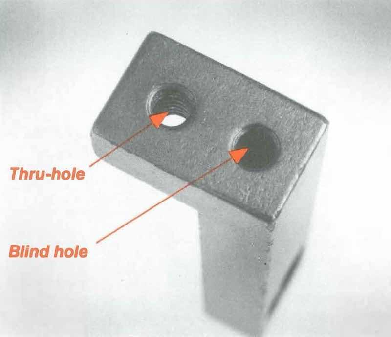 Figure 3: Threads of thru-hole receive plating. Blind hold traps solution, preventing desired coverage and promoting rust.Most seasoned platers would groan at the sight of the L-bracket shown in Figure 3. It has two tiny 6/32 threaded holes — normally no problem, since the holes are close together. But one is a thru-hole, and the other is blind. The thru-hole plates; the blind hole doesn’t. How do you keep their dimensions accurate?
Options here include:
- Instructing the machinist to tap both holes to size and have the plater mask them, or
- Having him tap the blind hole to size (since it won’t plate) and apply an oversized tap on the thru-hole (where a dimensional increase will occur).
Most machinists instinctively choose the first option because the part is more exact when it leaves their hands. The second option could produce parts at a lower cost on the plating end, but it’s impractical because it complicates the overall manufacturing process.
Talk is Cheap. Reprocessing Isn’t
When all is said and done, plating thickness will always be a function of the current distribution. Except on a few isolated shape-spheres, for instance, the current distribution will always be uneven, and so will the plating.
With this in mind, manufacturers need to know just how the finisher plans to process the part and how the processing will affect dimensions. If one plater processes a long bar horizontally because he has a long tank, while another runs it vertically because his tank is deep, the results may differ dramatically. Different shops might approach the same plating task differently due to tank dimensions, type of solution, size and volume of parts, and dozens of other factors.
This brings us back to that basic requirement of successful metal finishing: clear, open communications — preferably at every stage, from design, through manufacturing and machining, to the finishing process the plater conducts.
We all need to investigate, communicate, and talk. In this age of zero inventory, dock-to-stock, and just-in-time delivery, there’s only the time to do it right, not the time to do it over.
Milt Stevenson Jr. is Vice President and Chief Environmental Officer at Anoplate in Syracuse, New York. His father founded Anoplate in 1960, and it operates in a 104,000-square-foot facility. Milt is an active member of the finishing industry and its association and was named an NASF Fellow in 2019 for his lifelong work and dedication to the industry. Visit www.Anoplate.com.