A reader contacted me about their reel-to-reel plating operation, which has seen heavy management turnover over the past 10 years and is now operated under less-than-ideal conditions.
 Frank AltmayerThe manager was faced with the task of improving product quality and productivity, and had a number of issues that that he needed recommendations on:
Problems with the Equipment
- They would like to reduce high temperatures and humidity levels within the area.
- Chemical solution is drawn up into the hoods. Hoods and vents are hard to clean out. They become packed with chemical residues which reduce overall air flow.
- They need a new design on tank covers to aid in minimizing heat and moisture into the current environment and to keep the baths free of contaminants. Their existing covers have been warped with heat and age.
- The location of filters and pumps on tanks are in locations that are difficult to access; most of these are behind the line amidst piping, etc.
- They have issues with associates filling tanks and leaving hoses in the tanks, causing tanks to overflow and fill up the containment pits.
Line Speed Issues
- They need a 5% increase in production each year, and asked what specific actions can be taken to increase plating speed?
I paid a visit to your facility and made the following observations:
High Temperatures and Humidity
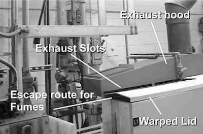 Photo 1This condition is caused by the poorly designed ventilation system currently employed. The shortcomings are:
- The exhaust slots are located above the tank lids, but most all of the lids are warped. Mist, sprays and foam are drawn into the duct from under the lid on the backside of the tank, clogging the ductwork and reducing exhaust rates. Any fumes or escaping water vapor that leaves from the front of the lid is not captured, as the exhaust hood only draws from the backside to the lids (See Photo 1).
- The tanks covers are warped due to the close proximity between the hot liquids and the lids (See Photo 2).
- The sump tanks are not exhausted and are uncovered.
- The tank covers physically block the exhaust duct from properly ventilating the process.
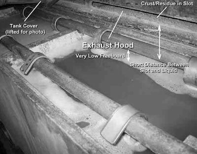 Photo 2Since replacing the entire ventilation systems and plating tanks is an expensive proposition we recommend that you consider modifying the ventilation system by adding artificial “freeboard” to the existing tanks. This can be accomplished by welding additional polypropylene onto the tops of the existing tanks as shown in the illustration in Photo 3.
While more costly, an over-all more effective recommendation would be to replace all process plating tanks and the entire exhaust system with new more modern technology. An example of a modern ventilated sump featuring in-tank filtration is shown in Photo 4.
The tank sumps need to have covers and exhaust ducts installed. These covers should be hinged so that they can not be totally removed. Water/chemical-proof switches can be installed to sound an alarm if a cover is not in place.
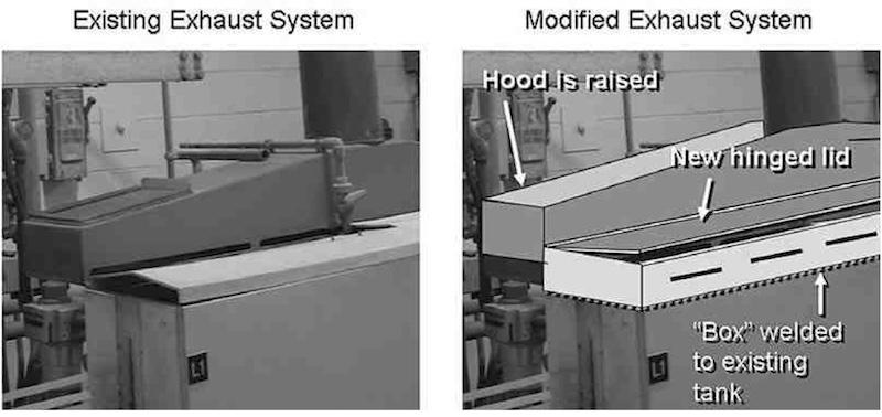 Photo 3: 1. Polypropylene “box” is welded onto existing tank, creating “artificial” freeboard; 2. Existing hood is raised 34”; 3. Slots are encased by box and are 34” higher up from solution top; 4. New hinged lids replace loose old lids; 5. Narrow slots in front of box allow air to flow into and over process solution and into hood slots, providing complete ventilation from all sides.
Location of Filters and Pumps
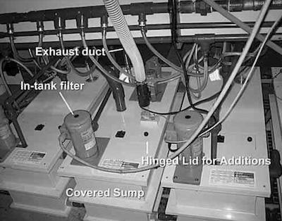 Photo 4Your sump tanks and filters are in locations that are difficult to access (most of these are behind the line amidst piping, etc.). The options for curing this issue include installing new sumps as per our above recommendation, or you can look into installing in-sump filters that take up less space.
Overflowed Sumps
This can be corrected by the installation of level switches and a solenoid controlled water addition system that would automatically keep each sump at a pre-determined level. An alternate system would sound an alarm when the level reached a low-low set point, allowing the worker to press a button to add the water, which then would automatically shut off when the correct level was reached.
Line Speed
The following are issues that can affect line speed.
1. Electrical connections
Electrical contact from the rectifier to the strip is made through use of capstan drives and rotary contacts at each end of the line (which is about 80 feet long). No additional contact is made with the strip. As a result, the distance between the rectifier and electrified cells are:
- Electroclean: 17 feet
- Copper Strike: 40 feet
- Copper Plate: 40 feet
- Tin Plate: 17 feet
The high resistance caused by the long length of strip between the electrical contacts is one of the reasons why this line can only be operated at 9 to 18 feet per minute maximum. The large distance between electrical contact and electrified cell(s) results in large voltage drops that limit plating current density and lower plating speed. On-site measurements that we made with a tong meter indicated that some plating cells are experiencing a 25% voltage drop from the rectifier to the plating cell.
As a rule, the optimum distance between electrical contacts to strip in a reel to reel plating line is between 24 and 30 inches for each electrified cell. Consideration should be given to installation of additional electrical (rectifier) contacts with the strip so that there is a contact before and after each plating cell. Manufacturers of equipment offer a variety of methods for making electrical contact that would not leave marks on the strip, including edge selective contacts which make contact only on the edges of the strip.
An even better (but more costly) solution would be to replace all of the processing cells with newer designs that incorporate more modern design, including optimized cell length, electrical contacts and freeboard.
2. One rectifier, two plating tanks
The copper strike and copper plating tanks should each have their own rectifiers. By running a single rectifier for two tanks it is impossible to optimize the current density of the copper plating cell. As a result, plating efficiency in the copper plate tank can not be optimized. As an alternate, we see no reason why the two copper plating solutions cannot be replaced by a single Rochelle-type copper plating solution.
Photo 5: Anode-cathode spacing.3. Anode-cathode spacing
The closer the strip runs to the anodes, the higher the plating efficiency and the faster the plating speed. Anode-cathode spacing is presently about 3” (See Photo 5). By reducing this to 2” or less (the closer, the better), plating speed can be increased by 30 to 50%, by allowing higher plating current densities. The spacing can be reduced by using wider anode baskets, or simply relocating the anode bars at the top of the tank.
4. Agitation
Almost all plating solutions can benefit from higher levels of agitation. In the plating solutions employed on this line, the sole source of agitation is the movement of the strip itself (See Photo 6). The absence of additional agitation slows plating speed by limiting the employable current density. We noted that the low level of freeboard prevents the use of any significant increase in agitation (See Photo 6). If additional freeboard is created per our discussion last month, then the addition of mechanical agitation provided by eductors or recirculating pumps can allow for operation at higher current densities, thus improving plating speed.
Note that it is unwise to use air agitation in the tin and cyanide based solutions, as air agitation can oxidize tin(II) to tin(IV), and air agitation can increase carbonate production in cyanide solutions.
5. Maintenance.
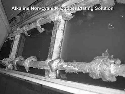 Photo 6: Tank with copper plating solution showing limited free- board and accumulated salts.Note that the tank bus in Photo 6 is heavily loaded with salt crystals. These can produce resistive connections between the anode bus and basket hooks, reducing the actual current delivered to the strip (and requiring a slowdown of the line). Maintenance personnel need to be made aware that the tank bus needs to be maintained in a clean, oxideand salt-free condition. If, for some reason, maintenance cannot keep up with the needs of the line, I would suggest bolting the anode hooks directly into the copper bus by tapping the hooks and copper bus and using thumb screws, to assure a firm level of electrical contact, even in the presence of salts.
Frank Altmayer is a Master Surface Finisher, an AESF Fellow, and the technical education director of the AESF Foundation and NASF. He owned Scientific Control Laboratories from 1986 to 2007 and has over 50 years of experience in metal finishing. He received the AESF Past Presidents Award, NAMF Award of Special Recognition, AESF Leadership Award, AESF Fellowship Award, Chicago Branch AESF Geldzahler Service Award, and NASF Award of Special Recognition.