Cardiovascular disease caused by the accumulation of atheroma plaques in the coronary arteries and the subsequent decrease in the blood flow through the affected vessel, known as atherosclerosis, is responsible for a high percentage of deaths worldwide.
 Marta Muñoz, Juan Pablo Fernández, Belén Torres, Nuria Pulido, Guangqi Zhang, Vesselin Shanov, Endzhe Matykina, and Joaquín Rams.Angioplasty is practiced to treat atherosclerosis which involves inserting a stent inside the occluded vessel to expand it and restore normal blood flow. In this work, temporary biodegradable stents made of AZ31 magnesium alloy have been fabricated using photo-chemical etching. The stents were coated via plasma electrolytic oxidation (PEO) technique. The radial strength of the stents was evaluated by cyclic compression, and the corrosion protection provided by the PEO coatings was studied by electrochemical and in vitro corrosion tests respectively. The stents showed an optimal maximum radial force of 0.147 N/mm and revealed elastic recuperation lower than 7 % of the total deformation after expansion.
The applied PEO coating helped to control the corrosion of the magnesium alloy, delaying its initiation and, once it has started, decreased the degradation rate compared with the bare AZ31 samples. Thus, the stents treated with the PEO coatings developed in this research present promising results for their use as temporary medical devices used in angioplasty.
1. Introduction
Magnesium and its alloys are light metals suitable for use in biomedical applications due to their good mechanical properties, biodegradability, non-toxicity, and biocompatibility [1]. Compared to traditional stent materials, such as stainless steel, Ti and its alloys, Mg alloys have a remarkable quality of self-degradation and complete resorption in the human body, making them an attractive option for temporal medical devices [2]. However, the pulsatile load of blood pressure (systolic and diastolic cyclic), the influence of body temperature (37 °C), and the relatively high corrosion rate of Mg in water-containing solutions such as blood, can lead to structural failure and collapse of the implanted stent before any vascular remodeling is completed [3].
Considerable effort has been devoted to the development of functional surface coating layers that can suppress fast corrosion of Mg stents and provide good vascular compatibility. Plasma electrolytic oxidation (PEO) [4] is a promising surface treatment process derived from conventional anodizing to form porous ceramic coatings with a composition, microstructure, porosity and roughness controlled by the electrical parameters of the process and the electrolyte composition. PEO coatings allow for a great control over the corrosion rate of Mg alloys and enables improved cell adhesion and proliferation [5] as well as tailors the overall mechanical behavior of the alloys [6].
However, the use of this technique is still limited in the biomedical industry due to its high cost, which is associated with great energy consumption stemming from the use of high voltage (200–400 V) and current density (10–60 A/dm2) along with long treatment times (10–60 min). In order to develop more efficient PEO processes, some alternatives have been explored such as modification of the deposition cell geometry, electrolyte, waveform design, etc. [[7], [8], [9]]. Another suitable low-cost alternative to improve the corrosion and fatigue behavior is to employ a flash-PEO process that consists of forming a thin ceramic coating (1–5 μm) in a short treatment time of 1–3 min. To the best of the authors' knowledge, flash-PEO coatings have not been explored on cardiovascular stents up to date, so they have a great potential for implementation in this field.
In the past, reports on Mg-based cardiovascular stents have been focused on the development of multifunctional composite polymeric coatings in order to improve the corrosion resistance and prevent late stent restenosis [[10], [11], [12], [13], [14]]. Despite the good results obtained in terms of corrosion resistance, mechanical properties and vascular compatibility in these reports, the poor adhesion of the polymer layers with Mg-based substrates has to be considered [15]. This could lead to undesirable interfacial failure and detachments. To the best of our knowledge, it has not been possible to successfully develop a single coating on Mg-based stents with an acceptable corrosion rate and long-term structural stability in the human body environment. The interfacial bonding with the Mg-based stent is an important factor that can affect the quality and stability of the coating because it must remain smooth, without cracking or flaking before and after balloon expansion. Consequently, the PEO process could be a suitable candidate for its use in cardiovascular stent protection due to its good mechanical properties, corrosion resistance and biological performance, which are required for the initial implantation phase.
Our literature search showed that no data focusing on the combined mechanical and corrosion performance of flash-PEO systems on Mg stents were available. In this work, the development of the flash-PEO coating on bulk AZ31 alloy specimens and stents made of AZ31 in terms of mechanical properties and corrosion behavior was carried out.
2. Materials and Methods
2.1. Photochemical etching of biodegradable metals for stent fabrication
University of Cincinnati has developed and patented a novel approach for patterning of biodegradable metals and employing it to fabricate medical devices such as stents, meshes and staples [16]. Most of these devices have been tested in vitro and in vivo. Details about the device fabrication using photo-chemical etching of biodegradable metal sheets have been previously published by the Cincinnati group [[17], [18], [19]]. The starting material was a rectangular sheet of AZ31 (99.9 %) with dimensions 250 mm × 250 mm and a thickness of 250 μm (Goodfellow, Oakdale, PA). The photo-chemical etching method transfers a selected pattern of the stent onto the metal sheet followed by chemical etching Fig. 1 [19].
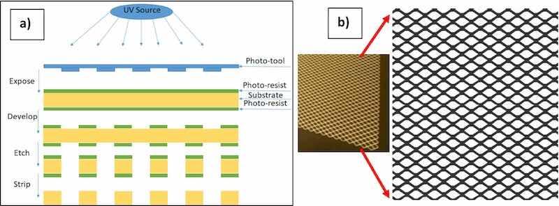
Fig. 1. (a) Photo-chemical etching method, (b) Picture of the patterned AZ31 magnesium sheet and enlarged pattern.
For stent fabrication, the etched sheet with desired dimensions was rolled to a cylinder and laser-welded along the side seam [17]. The dimensions of the manufactured stents varied from 20 mm to 30 mm length and from 3 mm to 9 mm in diameter, depending on the applications.
The photochemical etching approach is simple, offers high throughput and does not generate residual stress in the stent. It allows making different stent designs (rhombus, U, and Omega) as shown in Fig. 2 [18].
![Fig. 2. Modified and adapted from B.S.P.K. Kandala et al. [18] under the Creative Commons Attribution (CC BY 4.0) license . Pictures of AZ31 stents made by photochemical etching with different design. (a) Rhombus design; (b) U-design; (c) Omega design.](/images/images/whitepapers/peoAZ31magnesium/2.jpg)
Fig. 2. Modified and adapted from B.S.P.K. Kandala et al. [18] under the Creative Commons Attribution (CC BY 4.0) license . Pictures of AZ31 stents made by photochemical etching with different design. (a) Rhombus design; (b) U-design; (c) Omega design.
Two different sample configurations were used in this research to study the corrosion protection of the PEO coatings on AZ31 magnesium alloy substrates (called “plate” from now on) and AZ31 magnesium stent (called “stent” from now on). AZ31 plate samples of 1.5 × 1.5 × 0.3 cm were PEO coated. Before coating, the samples were grounded using SiC papers up to grain size of 1200. Then, the samples were cleaned and degreased in an ultrasonic isopropanol bath for 10 min. AZ31 stents were fabricated by photochemical etching of a 250 μm thick foil of AZ31 alloy [20] with a diameter of 4 mm and a length of 25 mm. AZ31 plate and stent's geometries are shown in Fig. 3.
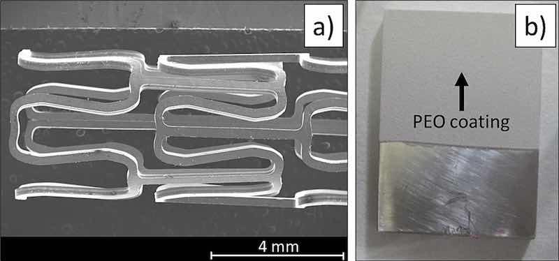
Fig. 3. (a) SEM image of a photochemically etched AZ31 stent. (b) Macroscopic image of PEO coated AZ31 plate.
2.2. Coating deposition and its material characterization
For applying of the PEO coating, the samples were immersed in an electrolyte which composition, shown in Table 1, was developed in previous research [21].
Table 1. Electrolyte composition for the PEO coating process.
| Compound | Concentration (g/L) |
| Na3PO4 · 12H2O | 10 |
| NaF | 8 |
| KOH | 1 |
| CaO | 2.9 |
As the stents must be deployed and deformed during their implementation, thin films are preferred to protect their surface in order to decrease the damage and the detachment of the coatings. Thus, it is important to control the current density and the coating time during the PEO treatment in order to reach the desired thickness of the final coating. In this study, the PEO coatings were applied on stents as well as on 15 × 15 × 3 mm plate specimens by immersing the AZ31 samples in the electrolyte, which was stirred and cooled to maintain a stable electrolyte temperature of 20 °C. A square waveform AC current with 480 V (+430 V, −50 V) RMS (root mean square) voltage was then applied to the AZ31 samples. The current density was limited at 100 mA/cm2 at a frequency of 50 Hz, and it was applied for 60 s. The current reached the established limit and remained steady after 20 s. A 316 L stainless steel mesh was used as a counter electrode. Upon the coating procedure was completed, the samples were rinsed in distilled water and isopropanol, and dried with warm air. The coatings created on the AZ31 plate samples were evaluated to verify that its set parameters have been achieved. Then five stents made out of AZ31 magnesium alloy were coated with the same parameters used in the case of the AZ31 plates. A system was developed with a titanium hook that acted both as a holder for the stent inside the electrolyte and an electrical connection for the working electrode during the PEO process (Fig. 4).
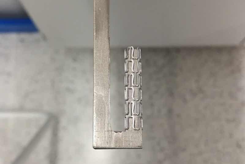
Fig. 4. Stent inserted on a titanium hook prior to the PEO process.
Scanning electron microscopy (Hitachi S-3400 N) was used to evaluate the thickness and the surface of the PEO coatings created on the surface of the AZ31 plates and on the AZ31 stents.
X-Ray diffraction (XRD) (PANalytical Xpert Pro MRD) was used to analyze the final composition and the different phases present in the PEO coating. The XRD pattern was obtained in Bragg-Brentano mode by varying 2Ɵ values between 10° and 80° (0.04° step size, 1 s per step).
2.3. Corrosion test
Different electrochemical tests were carried out (Metrohm Autolab PGSTAT302N) using coated plate specimens to assess the resistance against corrosion provided by the PEO coatings. First, linear polarization resistance (Rp) tests were performed. In this case, a three-electrode cell configuration was used in which a graphite rod was used as counter electrode, an Ag/AgCl electrode as reference electrode, and the studied sample acted as working electrode, with a surface area of 0.75 cm2 exposed to the electrolyte. Hanks' solution (CaCl2 (0.1396); MgSO4 (0.09767); KCl (0.4); KH2PO4 (0.06); NaCl (8.0); Na2HPO4 (0.04788) and d-Glucose (1.0) in g/L) was used as electrolyte to simulate the composition of the biological environments for in vitro corrosion tests. Upon1 h of stabilization time, the samples were polarized with ±10 mV around the corrosion potential, Ecorr, value, using a scanning rate of 1 mV/s. Measurements were taken after 1 h, 24 h, 72 h and 168 h of immersion.
Electrochemical anodic-cathodic potentiodynamic polarization tests were performed using the same cell configuration and electrolyte exposed for the linear polarization resistance tests. After 1 h of stabilization, measurements were made applying a polarization range of 1000 mV (−400 mV, +600 mV) around the Ecorr, using a scanning rate of 1 mV/s.
Electrochemical impedance spectroscopy (EIS) tests were conducted to evaluate the evolution of the corrosion behavior of the PEO coated specimens. The same electrolyte and cell configuration described in the previous electrochemical tests were used in this case. Measurements were made after 1 h, 24 h, 48 h, 72 h, 96 h and 168 h of the sample's immersion in the Hanks' solution. The frequency range used was selected from 105 Hz to 10−2 Hz, and the voltage amplitude was 10 mV with respect to the open circuit potential. The experiments were performed at the open circuit potential after 1 h of stabilization time before each measurement.
The hydrogen evolution tests were carried out using the setup described elsewhere [22]. Prior to the experiments, the solution was saturated with H2 during 24 h using scrap Mg alloy specimens. During the test, the plate samples were immersed in Hanks' solution for 110 h at a controlled temperature of 37 °C and pH of 7.4 ± 1 to simulate the biological conditions. The evolved H2 was collected inside a 25 mL burette connected to a funnel placed over the samples and filled with the testing electrolyte. Thus, the H2 bubbles generated during the corrosion of the samples were collected inside the burette where the volume of evolved H2 can be registered along the experimentation time.
After conducting different corrosion tests, scanning electron microscopy (Hitachi S-3400 N) was used to evaluate the evolution of the corrosion process for samples treated with the PEO coatings at different immersion times. Also, SEM was used to compare the degradation of the bare AZ31 samples and the coated samples after 110 h of immersion in Hanks' solution at 37 °C.
2.4. Mechanical testing of uncoated rhombus AZ31 stent
Rhombus AZ31 stents were evaluated by compressing them under load after the initial balloon expansion [17]. This procedure was applied for any pattern design of the stents and was conducted to assess the radial force and the minimal radial recoil. Before conducting the compression test, stents with 4 mm initial outer diameter were dilated with identical balloon catheters to 6.1 mm outer diameter and left to settle plastically until they reached an outer diameter of 5.7 mm (di). Upon expanding, the radial force of each device was evaluated by conducting a compression test using an instrument UniVert (Cell Scale Biomaterial Testing, Canada) with a 10 N load cell [18].
Initially, the system was set to zero corresponding to the diameter (di). Then the stents were compressed between two parallel flat plates with a step reduction of 0.04 mm. The gap between the plates was reduced to the final position of 50 % of the initial stent diameter (di). The resistive force utilized by the expanded stent was recorded during the loading and unloading cycles. The obtained hysteresis curve illustrates the crush resistance of the AZ31 stent. The resistive force was calculated following Eq. (1)
Radial force (N/mm) = The maximum resistive force exerted(N) / The total length of the stent (mm) (1)
The maximum radial force of a stent depends on the material used and its design. Rhombus pattern AZ31 Mg stents were tested under compression. Resistance force generated by the stent was recorded in loading and unloading mode [17]. A maximum value of 0.147 N/mm radial force (force over stent length) was calculated for the stent with rhombus design. This value is in the “sweet spot” when compared to the other AZ31 Mg stents with different pattern designs fabricated by our group. The obtained radial force falls in a similar range (0.1–0.25 N/mm) compared to a Zn stent fabricated by photo-chemical etching, as reported by our group [18].
The PEO-coated AZ31 stent samples were also tested under balloon expansion to investigate the coatings integrity. The coated stents were attached to a balloon catheter as shown in Fig. 5. The stent sample was expanded from its original diameter 4.5 mm to 8.3 mm and then the PEO coating was examined.
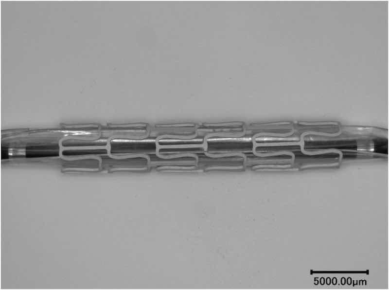
Fig. 5. PEO coated AZ31 stent attached to a balloon catheter.
3. Results and Discussion
3.1. Coating assessment
Fig. 6 shows SEM micrographs of the cross-section and plain view of the PEO coatings obtained on AZ31 plate specimens, respectively. SEM was used to evaluate the thickness of the coatings, and the acquired value was 2.8 ± 0.5 μm. The coating revealed a double layer structure (Fig. 6 a), with a porous and partially cracked top surface which is characteristic for these coatings due to their nature and their formation mechanism (Fig. 6 b). The coating also has an inner layer that is in contact with the surface of the AZ31 substrate and provides the barrier effect thus securing corrosion protection of the base metal (Fig. 9a). The zone of the inner layer is just less than 1 μm thick, dense and well adhered to the substrate. However, it also reveals a low presence of micro-defects. Figs. 6 (c, d) confirmed that the PEO coating was also reproducibly and uniformly formed on the AZ31 stents.
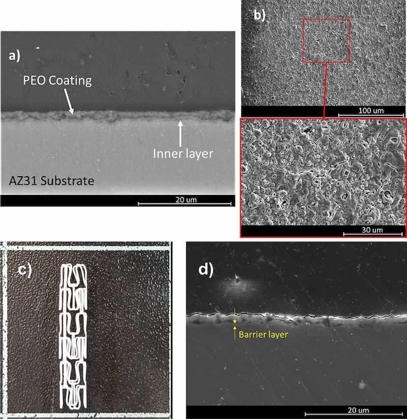
Fig. 6. (a) Cross-section view of the PEO coating formed on the AZ31 plate. (b) Plain view and a magnified area below from the surface of the PEO coating on the AZ31 plate. (c) Picture of PEO-coated AZ31 stent. (d) Cross-section revealing the interface of the PEO coating with the AZ31 stent imaged by SEM in a secondary electron mode.
Fig. 7 displays the XRD diffraction pattern obtained from the PEO coating on the AZ31 substrate. It shows that the coating is composed mostly of magnesium oxide formed during the corrosion of the AZ31 substrate. Magnesium peaks are also detected from the underlying substrate due to the relatively small thickness of the coating. Also, the detected magnesium fluoride is a product from the reaction of the substrate with the elements present in the electrolyte. In addition, calcium fluorophosphate is also present in the coating as a result of the reactions between some components of the electrolyte, such as Na3PO4·12H2O, NaF and CaO. This chemistry takes place inside the plasma micro discharge channels during the coating formation.
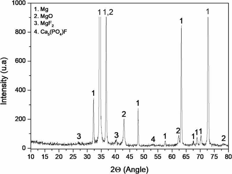
Fig. 7. XRD diffraction pattern of the PEO coating generated on the AZ31 substrate.
3.2. Corrosion tests
Fig. 8 shows the polarization resistance values for bare AZ31 and PEO coated samples over 168 h of specimen's immersion in the Hanks' solution. After 1 h of immersion, the polarization resistance for the coated sample is twice greater than the one for bare AZ31 substrate. During the first 24 h of immersion, the polarization resistance values of both materials decreased significantly, although the reduction was more pronounced for the PEO coated sample. However, the latter remained higher than the value of the bare AZ31 sample. This behavior can be explained by two different mechanisms depending on the nature of the samples. For bare AZ31 substrate, the layered corrosion products formed on the surface of the sample in the presence of water from the Hanks' is mainly composed of MgO and Mg(OH)2 [23, 24]. The solubility of Mg(OH)2 is low; therefore, it forms a stable protective layer on the surface of the AZ31 substrate in presence of water. However, the polarization resistance for this sample is lower after the initiation of the corrosion process, indicating that the corrosion products created on its surface does not provide effective protection, which is typically attributed to poor adhesion along with loose and cracked morphology of the formed corrosion layer. On the other hand, published data show that Mg(OH)2 layer reacts with Cl−-rich environment and form MgCl2 that dissolves easily in an aqueous environment thus does not providing protection against corrosion for the underlying substrate [25].
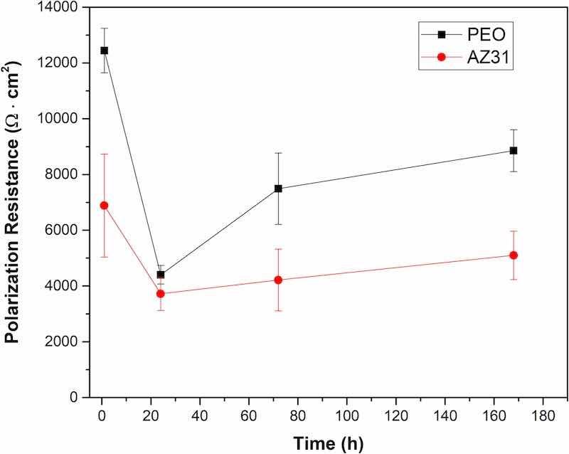
Fig. 8. Linear polarization resistance values for PEO coated and bare AZ31 substrates over 168 of immersion in Hanks' solution.
In the case of the PEO coated samples, as previously described the barrier effect to protect the metallic substrate from the Hanks' solution is provided by a thin intermediate layer with thickness less than 1 μm. However, this inner layer may present defects where the electrolyte can pass through in its way to the surface of the metallic substrate, particularly upon prolonged exposure. Thus, after 1 hour of immersion, the electrolyte has not yet reached the surface of the substrate, yielding high polarization resistance values compared with those for the bare substrate. However, 24 h is enough time for the electrolyte to pass through the pores and the defects of the inner PEO coating and react with the surface of the metallic substrate, which results in a decrease of the polarization resistance, as observed in Fig. 8.
After passing 24 h of immersion a rise in the polarization resistance is seen for both PEO coating and bare AZ31. However, this increment is only significant for the samples treated with the PEO coatings, reaching values that are twice as high as those for bare AZ31 substrates. It has been reported that PEO coatings reveal a self-sealing process that allows them to maintain their protection for a longer times [26, 27]. This self-sealing mechanism is based on the hydrolysis of the oxides and the compounds of the PEO coating in contact with the aqueous electrolyte. The products generated during the hydrolysis are then re-deposited and accumulated inside the pores of the PEO coating thus sealing them and increasing the dielectric behavior provided by the coating. Also, the build-up of undercoating corrosion products provides an additional protection, which will be further discussed later on when revealing the corrosion morphology.
Published data related to PEO coatings on magnesium substrates claim much higher polarization resistance than the values obtained in the present study [21]. However, it must be noticed that one of the goals of this research is to create thin layers of a few microns in order to control the degradation rate of the stents once implanted in arteries, and not to completely avoid the degradation of the implants. Thus, thin corrosion-protective films are more effective to let the stents degrade and also to decrease the generation of defects within the PEO coating during the balloon expansion of the stents.
Fig. 9 shows the polarization curves for bare AZ31 and PEO coated substrates after 1 h of immersion in Hanks' solution. As previously demonstrated regarding the polarization resistance values, the presence of a thin PEO coating provides excellent protection against corrosion for short immersion time. At this point, the electrolyte has not been able to pass through the pores and the defects of the inner layer of the PEO coating to reach the surface of the metallic substrate. Thus, the Ecorr of the PEO coated sample is less electronegative and the current density passing through this system is one order of magnitude lower than the value for the bare AZ31 substrate. This is because the layered corrosion products for the base metal is composed of magnesium oxides and chlorides which do not provide any effective protection against corrosion. The values of Ecorr and current density for both materials are shown in Table 2.
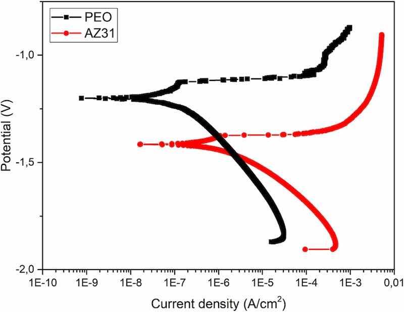
Fig. 9. Polarization curves for the PEO coated and bare AZ31 substrates after 1 h of immersion in Hanks' solution.
Table 2. Ecorr and current density values extracted from the anodic-cathodic polarization tests.
| Empty Cell | Ecorr (V) | i (A/cm2) |
| PEO coated | −1.2 | 1.4E–7 |
| Bare AZ31 | −1.4 | 1.9E–6 |
Fig. 10 shows the Nyquist and Bode plots obtained from PEO coated AZ31 substrate by electrochemical impedance spectroscopy tests after different immersion times (1 h, 24 h, 48 h, 72 h, 96 h and 168 h) in Hank's solution. The initial (1 h) value of |Z|10mHz is at least an order of magnitude greater than those typically reported in the literature for bare AZ31 alloy in physiological media [22, 28].
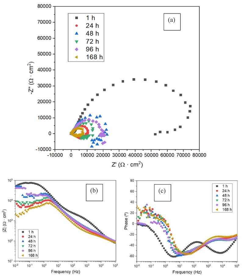
Fig. 10. EIS curves for PEO coated AZ31 substrate obtained after different immersion time: a) Nyquist plot, b) Bode plot of total impedance modulus, (c) Bode plot of phase angle.
From Fig. 10 is clear that as the immersion time increases, the corrosion resistance decreases. This can be deduced from the decrease in the diameter of the capacitive loop in the Nyquist plot (Fig. 10a), and the reduced values of modulus of impedance with time from the Bode plot following 24 h of immersion (Fig. 10 b and c). As observed in the Bode plot (Fig. 10 b and c), at higher frequencies (103–104 Hz) a time constant associated with the outer porous layer of the PEO coating can be identified. At frequencies close to 10 Hz an additional time constant associated to the inner barrier layer of the coating can be recognized. The inner barrier layer is responsible for the corrosion resistance of the coating [29]. However, the outer layer presents interconnected porosity [30], which facilitates the penetration of the electrolyte through this part of the coating causing its degradation. This can be observed from the decrease in the time constant at high frequencies after 24 h of immersion in Hank's solution.
Importantly, the total impedance modulus at low frequencies recovers after 48 h and 96 h of immersion, compared with the 24 h and 72 h time points, respectively. These fluctuations can be related to the self-sealing effect of the porous PEO coatings. This effect can be a consequence of two factors. On one hand, Mg(OH)2 is a corrosion product that is generated during corrosion of magnesium in aqueous media. In the case of the PEO coated sample, this product is generated on the interface between the magnesium substrate and the PEO coating thus filling cracks and pores of the inner layer of the PEO coating. Although Mg(OH)2 is not stable for pH values lower than 10.5 [31], alkalization of the medium promoted by the generation of OH− during the corrosion process of magnesium occurs inside the cracks and pores of the inner layer coating layer.There the volume of the electrolyte is low [32] which allows reaching pH values higher than 10.5. This local environment stabilizes the formed corrosion product Mg(OH)2 which starts filling the defects of the coating thus increasing its dielectric behavior and overall, the protective properties of the coating. The second favourable factor is associated with sealing the pores of the outer PEO layer c via accumulation of hydrolysis products from the compounds and oxides of the coating causing increasing the dielectric properties of the coating to some extent [26]. The latter may also be facilitated by the intrinsic capacity of fluorapatite generated in the coating (Fig. 6) to chemisorb water [33],and locking it in place thus detaining the permeation of the barrier layer of the PEO coating.
Fig. 11 shows the results of the hydrogen evolution tests during 110 h of immersion in Hanks' solution at 37 °C and pH of 7.4.
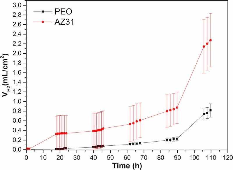
Fig. 11. Hydrogen volume generated from the PEO coated and the bare AZ31 substrates after 110 h of immersion in Hanks' solution at 37 °C.
For the bare AZ31 substrate, a remarkable increment in the volume of H2 is observed for the first 24 h of immersion. There, the volume of H2 increased continuously from 24 h to 90 h of immersion. Further, a jump in hydrogen evolution is noticed from 90 h until the end of the experiment reaching values around 2.3 mL/cm2. These fluctuations in the amount of evolved H2, and therefore in the degradation rate of the samples, are a consequence of the low passivation properties of the corrosion products layer formed during the corrosion process of the AZ21 sample in the presence of Cl− from the electrolyte. Throughout the entire experimentation time, the volume of H2 generated from the bare AZ31 substrate is significantly higher compared with the volume generated from the PEO coated samples. In the case of the PEO coated samples, the evolution of H2 starts from ∼48 h of immersion onwards, but the increment in H2 volume is insignificant until 90 h of immersion in the Hanks' solution. This behavior indicates that, by that experimentation time, the electrolyte was able to reach the surface of the metallic substrate only at some points of the surface of the sample. Overall, the magnitude of the corrosion in this case was negligible, not only because of the barrier effect provided by the PEO coating, but also because of its self-sealing properties. However, from 90 h of immersion until the end of the experiment, a significant increment in the volume of evolved H2 is observed, reaching a final value around 0.8 mL/cm2 at 110 h which value is significantly lower than that obtained for the bare substrate. At the end of the experimentation time the electrolyte is expected to reach the surface of the PEO coated samples and corrosion started to spread all over the surface of the metallic substrate, along the interface between the sample and the coating. It is obvious from the conducted experiment that the hydrogen evolution behaves in two different ways. For both materials, the hydrogen evolution rate reveals a remarkable increment after 90 h of immersion.
The corrosion reaction of magnesium in aqueous solutions (Eq. (2)) makes it possible to relate the H2 generated for each condition with the amount of degraded magnesium. Moreover, the corrosion rate of the magnesium samples in mm per year can be obtained from the final volume of H2 measured for both materials using the relation shown in Eq. (3) [21].
Mg + 2H2O ↔ Mg2+ + 2OH− + H2 (2)
CR = 2.279 × VH2 (3)
The values of evolved hydrogen in mL/(cm2day), as well as the corrosion rate in mm/year for both conditions, are shown in Table 3. As displayed there, the presence of the PEO coating decreases about 3 times the corrosion rate of the bare AZ31 magnesium alloy.
Table 3. Corrosion rate extracted from the H2 evolution tests.
| Empty Cell | H2 (mL/(cm2day)) | Corrosion Rate (mm/y) (CR = 2.279 × VH2) |
| PEO coated (90 h) | 0.05 | 0.11 |
| PEO coated (110 h) | 0.19 | 0.43 |
| Bare AZ31 (90 h) | 0.18 | 0.41 |
| Bare AZ31 (110 h) | 0.49 | 1.11 |
From these values and taking the total surface of the stent into account, which is about 4 cm2, a daily evolution of hydrogen from a stent immersed in a simulated body fluid can be deduced. Thus, up to 90 h of immersion, the bare AZ31 substrate with the same surface area will generate about 0.72 mL/day of H2, and the PEO coated sample will evolve about 0.2 mL/day. After 90 h of immersion until the end of the experimentation time, the bare AZ31 stent would generate about 2 mL/day of H2, and the coated stent would produce about 0.76 mL/day. These values, especially the one referred to the PEO coated stent, are comfortably low for the human body to assimilate and eliminate them with no adverse effects [34]. Further, the bloodstream inside the vessel where the stent could be implanted, would carry the generated H2 bubbles thus dispersing the hydrogen gas throughout the body blood system and thereby facilitating its assimilation and elimination. Hydrogen has been reported in the literature to quickly exchange through tissues in vivo and can accumulate in fatty tissue, also is more soluble in non-polar solvents than in body fluids [35]. The obtained results in this work show that the presence of the PEO coating efficiently protects the magnesium substrate up to 90 h of immersion, delaying the initiation of the degradation rate and decreasing the degradation once it has started.
For a better understanding the corrosion process of the PEO coated samples, cross-sectional SEM images have been taken which illustrated the evolution of the corrosion process on the AZ31 substrate protected with the PEO coating obtained at different immersion time up to 110 h in Hanks' solution at 37 °C. The results are displayed in Fig. 12.
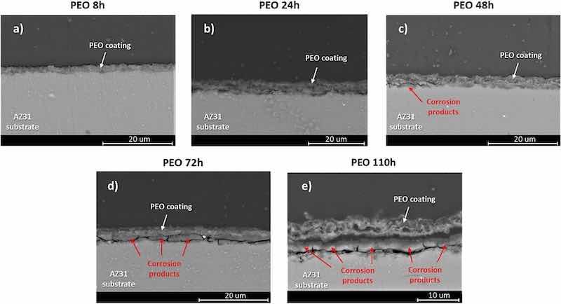
Fig. 12. Cross-sectional SEM images illustrating the evolution of the corrosion process on the AZ31 substrate protected with the PEO coating obtained at different immersion time up to 110 h in Hanks' solution at 37 °C.
As previously discussed, PEO coatings are inherently porous, but this porosity is mostly present only within their outer layer. However, the inner layer of the coating, which is thinner than the outer one, but relatively compact with nano-size defects [36], provides an effective barrier effect thus delaying the access of the electrolyte to the surface of the metallic substrate. After 8 h of the immersion in Hanks' solution (Fig. 12 a), no signs of initiation the degradation process are visible on the AZ31 substrate. By this time, the surface of the metallic substrate is successfully isolated from the electrolyte. This behavior is evident from different electrochemical experiments where after 1 h of immersion, the current density extracted from the anodic-cathodic polarization of the PEO coated sample was one order of magnitude lower than the value for the AZ31 substrate. Also, the polarization resistance for the PEO coated sample was about twice the value of the bare substrate. Moreover, the H2 volume measured during the first hours of the hydrogen evolution experiment reinforced the notion that at the beginning of the immersion time, the PEO coatings provide effective protection against corrosion.
After 24 h of immersion no significant signs of corrosion are visible on the surface of the metallic substrate treated with the PEO coating (Fig. 12 b). The micrograph is consistent with the results extracted from the hydrogen evolution test, where the volume of H2 reaches a negligible value of 0.02 mL/cm2 after 24 h of immersion. However, the polarization resistance value for the PEO coated samples after 24 h of immersion has suffered a sharp drop compared with the value at the beginning of the immersion. Although it is a significant decrease in the polarization resistance value, it does not necessarily is related to an abrupt increment in the degradation of the metallic substrate. Rather it may be associated with the fact that 24 h of immersion provides enough time for the electrolyte to completely fill the pores of the outer layer of the PEO coating, and also to pass through the micro-defects that can be present in the protective inner layer of the PEO coating interfacing with the surface of the AZ31 substrate. Thus, the dielectric behavior of the coating suddenly decreases as the current finds ways to reach the metallic sample.
After 48 h of immersion, local failure is visible at the points where the electrolyte reaches the surface of the substrate through the microdefects in the inner PEO layer (Fig. 12c). Here, several aspects of the sample's behavior can be highlighted. First, the results show that the hydrogen evolution has slightly increased as a consequence of the initiation of the corrosion process, but still displays a very low value compared with that obtained for the bare AZ31 sample. On the other hand, the polarization resistance of the coated sample increases reaching a value that is almost twice as the value of the bare AZ31 substrate. The fact that, by this time, the corrosion starts but the polarization resistance increases, can be explained by two processes taking place at the same time. First, as the corrosion takes place at the interface between the surface of the metallic substrate and the PEO coating, the corrosion products that are generated grow thus sealing the microdefects in the inner layer of the PEO coating. As previously revealed, these corrosion products are only partially stable, but their presence helps to temporary isolate the substrate from the electrolyte. Also, the self-sealing effect of the PEO coatings help to decrease, to some extent, the porosity of the outer layer, again improving the barrier effect of the coating. The combination of these processes results in an increase in the coating's dielectric behavior and, therefore, in the polarization resistance value of the coated sample.
As immersion time increases, the corrosion process spreads under the PEO coating and the volume of corrosion products increases until it reaches thickness comparable to that of the PEO coating (Fig. 12d). Moreover, the layer of the corrosion products starts to cause detachment of the PEO coating from the substrate. Thus, the metallic substrate is exposed to the electrolyte which can infiltrate through the detached PEO coating and also via the cracks and defects of the layer from corrosion products. By this time, the hydrogen evolution from the PEO coated sample slowly rises, however remains still much lower than that of the bare AZ31 substrate. The polarization resistance remains significantly higher in the case of the coated sample.
At the end of the experimentation time (110 h), the layer of corrosion products has grown significantly and the PEO coating over it is totally detached (Fig. 12e) which precluded further protect the substrate. However, it should be highlighted that, although corrosion takes place under the PEO coating, it is restricted to the zones where the inner PEO layer is damaged or microdefects are generated during the formation of the coating. However, after 110 h of immersion certain zones on the surface of the metallic substrate appear that are only slightly affected by corrosion. The PEO coating still remains adhered on the thin layer of corrosion products that is formed on the AZ31 substrate due to the low thickness of the PEO coating. On the other hand, in the case of bare AZ31 substrates, the whole surface of the samples was affected by corrosion.
Fig. 13 and Table 4 show Energy Dispersive Spectroscopy (EDS) analysis of the PEO coating after 48 h of immersion in the electrolyte. The elemental analysis of the coating at points 1, 3, and 5 reveals the presence of O, Mg, Ca, and P. O and Mg can be attributed to the corrosion products resulting from the degradation of the magnesium substrate, typically MgO and Mg(OH)2.
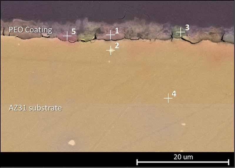
Fig. 13. EDS analysis of PEO coated sample after 48 h of immersion in Hanks' solution.
Table 4. Elemental analysis obtained from the sample displayed in Fig. 13.
| Element | Point 1 | Point 2 | Point 3 | Point 4 | Point 5 |
| C | 18.6 | 10.5 | 36.8 | 15.5 | 18.0 |
| O | 45.3 | 2.2 | 31.0 | – | 43.1 |
| Mg | 16.1 | 61.7 | 10.5 | 81.3 | 17.5 |
| Al | 2.2 | 19.6 | 0.8 | 3.2 | 2.4 |
| P | 5.0 | – | 2.2 | – | 5.4 |
| Ca | 4.3 | – | 4.5 | – | 4.4 |
| F | 5.5 | – | 11.5 | – | 6.4 |
| Na | 0.7 | – | 0.5 | – | 0.6 |
As previously mentioned, the accumulation of these corrosion products can provide temporary protection against corrosion, been responsible for the fluctuations in corrosion resistance observed in the Rp and EIS diagrams (Fig. 8, Fig. 10). On the other hand, Ca and P are elements present in the composition of the PEO coating. However, previous research [21] has shown that while P can be found throughout the volume of the coating, Ca tends to accumulate on the surface and outer layer of the coating during its formation. Therefore, the detection of Ca and P in the inner layers of the PEO coating suggests the presence of calcium phosphate compounds deposited within the inner pores of the PEO coating because of the hydrolysis of the coating material. These calcium phosphates can temporarily seal the inner pores of the coating, improving its dielectric behavior. Similar to the corrosion products from the degradation of the magnesium substrate, the accumulations of calcium phosphates sealing the coating can lead to fluctuations in the corrosion resistance of the coating, observed in Fig. 8, Fig. 10 between 24 and 48 h of immersion in the electrolyte.
Fig. 14 reveals the cross-section view micrographs of the corrosion process on PEO coated and bare AZ31 substrate after 110 h of immersion in Hanks' solution. The PEO coating still remains intact on the thin layer of corrosion products that is formed on the AZ31 substrate due to the low thickness of the PEO coating. This situation is depicted in the areas marked with yellow arrows in Fig. 14a. Deposits of corrosion products with different thicknesses can be found all over the surface of the samples in Fig. 14 b and c along with sites of localized corrosion on the bare substrates. Finally, the depth of the corrosion attack on the AZ31 bare substrates is almost double than the depth of the coated PEO samples. However, it must be noticed that these large pits are generalized over the surface of the bare AZ31 substrate, while their presence is much lower on the surface of the PEO coated samples and restricted only to those places where the electrolyte was able to reach the surface of the metallic substrate. Thus, by the assessment of the sample's surface after the immersion in Hanks' solution and based on the data extracted from the hydrogen evolution experiments, the degradation rate of the AZ31 substrates can be determined and controlled. The latter can be achieved via applying a thin PEO coating on the base metal which enables a dramatic decrease of the bare AZ31 degradation rate in contact with a simulated biological medium, making it possible to maintain the mechanical integrity of the magnesium alloy in physiological environments.
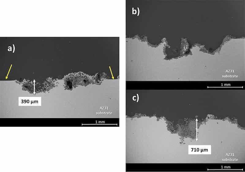
Fig. 14. Cross-section view micrographs for comparison of the corrosion process on PEO coated substrate (a), and bare AZ31 substrate (b and c) after 110 h of immersion in Hanks' solution.
In the future, the PEO technique can be used to create coatings on the surface of biodegradable stents made from this material thus decreasing the degradation rate and maintaining the mechanical properties of the coated stents for a long period upon implantation in the body. Thus, this procedure could be used for protecting the implanted biodegradable stents until the remodeling of the inner lumen of the vessel occurs.
The SEM image of expanded PEO coating on the AZ31 stent samples is shown in Fig. 15. It was observed in the zoom-in image that the same porous surface morphology as observed in Fig. 6b remains unchanged even after the stent diameter was dilated twice from its original value. A broader view in Fig. 15 showed that after the severe mechanical deformation, the PEO coating was able to stay overall intact and attached to the stent struts. It was noted that PEO coating peeling was observed for stents samples that went through a crimping and then expanding procedure. It is known that PEO coatings are susceptible to cohesive failure due to their multilayered microstructure [37], while the adhesion of protective barrier layer remains unaffected. Therefore, at such locations, only negligible loss of protective capacity would be expected.
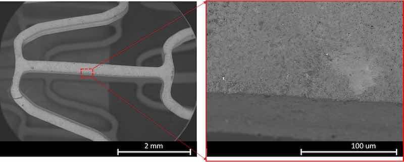
Fig. 15. PEO coating on AZ31 stent samples after conducting balloon expansion tests. Low magnification of stent segment with coating-(left). High magnification of a strut with the PEO coating intact-(right).
4. Conclusions
A PEO coating procedure has been developed and successfully applied for surface treatment of AZ31 bioresorbable stents manufactured by photochemical etching technology. The coating consisted of an external porous layer and an internal compact one. It was found that the external layer adhered well to the metal surface of the device while the inner one acted as a protective layer. The dilation tests showed that the PEO coating was able to survive the balloon expansion tests and remained intact as a surface barrier. The electrochemical tests revealed that the coating effectively protected the magnesium stents in the initial hours if immersion in Hanks' solution. A self-sealing effect that further protected the substrate has been observed from 24 h on thus increasing the corrosion resistance. This effect was stable, although the protection provided by the PEO coating was reduced after 168 h. Hydrogen evolution confirmed the electrochemical results and showed that the PEO coating nearly inhibited the corrosion of the stent during the first 90 h yielding a corrosion rate of 0.11 mm/year. The coating also enabled a reduction of the corrosion rate afterwards (CR = 0.43 mm/year) as compared with the uncoated stent (CR = 1.11 mm/year). The mechanism that was responsible for the corrosion in Hanks' solution has been discussed and determined. It was found that during the first hours of corrosion, the products formed by the degradation of the magnesium alloy, hydrolysis of the coating material and precipitation of Casingle bondP species were deposited within the pores of the PEO layer, causing a self-sealing effect. Local failure of the barrier layer because of its complete hydration caused undercoating propagation of corrosion process with formation of a continuous corrosion products layer. This reduced the protection capability of the coating, although it did not fully expose the substrate to the aggressive medium.
We believe this work resulted in creating a coating method for magnesium alloys, particularly AZ31, which allowed extending the in-service life of bioresorbable photochemically etched stents. The achieved corrosion rate may be considered compatible with the time required for the body to integrate the stent, with suitably low volume of generated hydrogen, while allowing the stent dissolution and hopefully remodeling of the stenotic artery. The latter must be tested by in vivo experiments using pigs, which may take place in the future.
Written by Marta Muñoza, Juan Pablo Fernándeza, Belén Torresa, Nuria Pulidoa, Guangqi Zhangb, Vesselin Shanovbc, Lara Morenod, Endzhe Matykinade, Joaquín Ramsa
- Area de Ciencia e Ingeniería de Materiales, ESCET, Universidad Rey Juan Carlos, C/Tulip´ an s/n, 28933 M´ ostoles, Spain
- Department of Mechanical and Materials Engineering, University of Cincinnati, OH 45221, United States of America
- Department of Chemical and Environmental Engineering, University of Cincinnati, OH 45221, United States of America
- Departamento de Ingeniería Química y de Materiales, Facultad de Ciencias Químicas, Universidad Complutense, 28040 Madrid, Spain
- Unidad Asociada al ICTP, IQM (CSIC), Grupo de Síntesis Org´ anica y Bioevaluaci´ on, Instituto Pluridisciplinar (UCM), Paseo de Juan XXIII 1, Madrid 28040, Spain
CRediT authorship contribution statement: Marta Muñoz: Writing – review & editing, Visualization, Validation, Supervision, Methodology, Formal analysis, Conceptualization. Juan Pablo Fernández: Writing – original draft, Software, Investigation, Formal analysis, Data curation. Belén Torres: Writing – review & editing, Supervision, Resources, Project administration, Methodology, Funding acquisition, Formal analysis. Nuria Pulido: Validation, Investigation, Formal analysis, Data curation. Guangqi Zhang: Validation, Software, Investigation, Data curation. Vesselin Shanov: Writing – review & editing, Software, Resources, Project administration, Methodology, Funding acquisition, Formal analysis. Lara Moreno: Writing – original draft, Validation, Software, Investigation. Endzhe Matykina: Writing – review & editing, Validation, Supervision, Methodology, Investigation, Formal analysis. Joaquín Rams: Writing – review & editing, Visualization, Supervision, Resources, Project administration, Funding acquisition, Formal analysis.
Declaration of competing interest: The authors declare that they have no known competing financial interests or personal relationships that could have appeared to influence the work reported in this paper.
Acknowledgment: The authors gratefully acknowledge the support of PID2021-124341OB-C21 and PID2021-124341OB-C22 (MICINN/AEI/FEDER, UE) and ADITIMAT-CM (S2018/NMT-4411, Regional Government of Madrid and EU Structural Funds). The UC team would like to acknowledge the support by NSF through grant EEC-0812348.
Data availability: The data that has been used is confidential.
References
[1] X. Gu, Y. Zheng, Y. Cheng, S. Zhong, T. Xi, In vitro corrosion and biocompatibility of binary magnesium alloys, Biomaterials 30 (2009) 484–498, https://doi.org/10.1016/j.biomaterials.2008.10.021.
[2] X. Chen, R. Chang, H. Liu, L. Zhang, Y. Zheng, Moving research direction in the field of metallic bioresorbable stents-a mini-review, Bioact. Mater. 24 (2023) 20–25, https://doi.org/10.1016/j.bioactmat.2022.12.004.
[3] S. Jafari, S.E. Harandi, R.K. Singh Raman, A review of stress-corrosion cracking and corrosion fatigue of magnesium alloys for biodegradable implant applications, Jom 67 (2015) 1143–1153, https://doi.org/10.1007/s11837-015-1366-z.
[4] M. Mohedano, X. Lu, E. Matykina, C. Blawert, R. Arrabal, M.L. Zheludkevich, Plasma electrolytic oxidation (PEO) of metals and alloys, Encycl. Interfacial Chem. Surf. Sci. Electrochem. (2018) 423–438, https://doi.org/10.1016/B978-0-12- 409547-2.13398-0.
[5] A. Santos-Coquillat, M. Esteban-Lucia, E. Martinez-Campos, M. Mohedano, R. Arrabal, C. Blawert, M.L. Zheludkevich, E. Matykina, PEO coatings design for mg-ca alloy for cardiovascular stent and bone regeneration applications, Mater. Sci. Eng. C 105 (2019) 110026, https://doi.org/10.1016/j.msec.2019.110026.
[6] A. Nˇ emcov´ a, P. Skeldon, G.E. Thompson, S. Morse, J. ˇ Cíˇ zek, B. Pacal, Influence of plasma electrolytic oxidation on fatigue performance of AZ61 magnesium alloy, Corros. Sci. 82 (2014) 58–66, https://doi.org/10.1016/j.corsci.2013.12.019.
[7] E. Matykina, R. Arrabal, M. Mohedano, B. Mingo, J. Gonzalez, A. Pardo, M. C. Merino, Recent advances in energy efficient PEO processing of aluminium alloys, Trans. Nonferrous Met. Soc. China. 27 (2017) 1439–1454, https://doi.org/ 10.1016/S1003-6326(17)60166-3.
[8] R. del Olmo, M. Mohedano, B. Mingo, R. Arrabal, E. Matykina, LDH post-treatment of flash PEO coatings, Coatings 9 (2019) 6–20, https://doi.org/10.3390/ coatings9060360.
[9] R. del Olmo, M. Mohedano, P. Visser, E. Matykina, R. Arrabal, Flash-PEO coatings loaded with corrosion inhibitors on AA2024, Surf. Coatings Technol. 402 (2020) 126317, https://doi.org/10.1016/j.surfcoat.2020.126317.
[10] W. Xu, K. Sato, Y. Koga, M. Sasaki, T. Niidome, Corrosion resistance of HF-treated Mg alloy stent following balloon expansion and its improvement through biodegradable polymer coating, J. Coatings Technol. Res. 17 (2020) 1023–1032, https://doi.org/10.1007/s11998-019-00284-5.
[11] Y. Shi, L. Zhang, J. Chen, J. Zhang, F. Yuan, L. Shen, C. Chen, J. Pei, Z. Li, J. Tan, G. Yuan, In vitro and in vivo degradation of rapamycin-eluting mg-Nd-Zn-Zr alloy stents in porcine coronary arteries, Mater. Sci. Eng. C 80 (2017) 1–6, https://doi.org/10.1016/j.msec.2017.05.124.
[12] M.H. Kang, K.H. Cheon, K. Il Jo, J.H. Ahn, H.E. Kim, H. Do Jung, T.S. Jang, An asymmetric surface coating strategy for improved corrosion resistance and vascular compatibility of magnesium alloy stents, Mater. Des. 196 (2020) 109182, https:// doi.org/10.1016/j.matdes.2020.109182.
[13] J. Liu, B. Zheng, P. Wang, X. Wang, B. Zhang, Q. Shi, T. Xi, M. Chen, S. Guan, Enhanced in vitro and in vivo performance of mg-Zn-Y-Nd alloy achieved with APTES pretreatment for drug-eluting vascular stent application, ACS Appl. Mater. Interfaces 8 (2016) 17842–17858, https://doi.org/10.1021/acsami.6b05038.
[14] W. Xu, K. Yagoshi, T. Asakura, M. Sasaki, T. Niidome, Silk fibroin as a coating polymer for Sirolimus-eluting magnesium alloy stents, ACS Appl. Bio Mater. 3 (2020) 531–538, https://doi.org/10.1021/acsabm.9b00957.
[15] Z.Q. Zhang, Y.X. Yang, J.A. Li, R.C. Zeng, S.K. Guan, Advances in coatings on magnesium alloys for cardiovascular stents – a review, Bioact. Mater. 6 (2021) 4729–4757, https://doi.org/10.1016/j.bioactmat.2021.04.044.
[16] V.N. Shanov, P. Roy-Chaudhury, M.J. Schulz, Z. Yin, B. Campos-Naciff, Y. Wang, Methods for making magnesium biodegradable stents for medical implant applications, US (2017), 9,655,752 B2.
[17] B.S.P.K. Kandala, G. Zhang, C. LCorriveau, M. Paquin, M. Chagnon, D. Begun, V. Shanov, Preliminary study on modelling, fabrication by photo-chemical etching and in vivo testing of biodegradable magnesium AZ31 stents, Bioact. Mater. 6 (2021) 1663–1675, https://doi.org/10.1016/j.bioactmat.2020.11.012.
[18] B.S.P.K. Kandala, G. Zhang, T.M. Hopkins, X. An, S.K. Pixley, V. Shanov, In vitro and in vivo testing of zinc as a biodegradable material for stents fabricated by photo-chemical etching, Appl. Sci. 9 (2019), https://doi.org/10.3390/ app9214503.
[19] B. Kandala, G. Zhang, X. An, S. Pixley, V. Shanov, Effect of surface-modification on in vitro corrosion of biodegradable magnesium-based helical stent fabricated by photo-chemical etching, Med. Res. Arch. 8 (2020), https://doi.org/10.18103/mra.v8i3.2067.
[20] J. Wang, V. Giridharan, V. Shanov, Z. Xu, B. Collins, L. White, Y. Jang, J. Sankar, N. Huang, Y. Yun, Flow-induced corrosion behavior of absorbable magnesium- based stents, Acta Biomater. 10 (2014) 5213–5223, https://doi.org/10.1016/j.actbio.2014.08.034.
[21] J.P. Fern´ andez-Hern´ an, A.J. L´ opez, B. Torres, E. Martínez-Campos, E. Matykina, J. Rams, Anticorrosion and Cytocompatibility assessment of graphene-doped hybrid silica and plasma electrolytic oxidation coatings for biomedical applications, ACS Biomater Sci. Eng. 7 (2021) 5861–5877, https://doi.org/ 10.1021/acsbiomaterials.1c00326.
[22] M. Daavari, M. Atapour, M. Mohedano, H.M. S´ anchez, J. Rodríguez-Hern´ andez, E. Matykina, R. Arrabal, A. Taherizadeh, Quasi-in vivo corrosion behavior of AZ31B Mg alloy with hybrid MWCNTs-PEO/PCL based coatings, J. Magnes. Alloy. 10 (2022) 3217–3233, https://doi.org/10.1016/j.jma.2021.09.010.
[23] Y. Xin, K. Huo, T. Hu, G. Tang, P.K. Chu, Corrosion products on biomedical magnesium alloy soaked in simulated body fluids, J. Mater. Res. 24 (2009) 2711–2719, https://doi.org/10.1557/jmr.2009.0323.
[24] Y. Xin, C. Liu, X. Zhang, G. Tang, X. Tian, P.K. Chu, Corrosion behavior of biomedical AZ91 magnesium alloy in simulated body fluids, J. Mater. Res. 22 (2007) 2004–2011, https://doi.org/10.1557/jmr.2007.0233.
[25] Y. Xin, T. Hu, P.K. Chu, In vitro studies of biomedical magnesium alloys in a simulated physiological environment: a review, Acta Biomater. 7 (2011) 1452–1459, https://doi.org/10.1016/j.actbio.2010.12.004.
[26] E. Wierzbicka, B. Vaghefinazari, S.V. Lamaka, M.L. Zheludkevich, M. Mohedano, L. Moreno, P. Visser, A. Rodriguez, J. Velasco, R. Arrabal, E. Matykina, Flash-PEO as an alternative to chromate conversion coatings for corrosion protection of mg alloy, Corros. Sci. 180 (2021) 109189, https://doi.org/10.1016/j.corsci.2020.109189.
[27] F.H. Cao, J.L. Cao, Z. Zhang, J.Q. Zhang, C.N. Cao, Plasma electrolytic oxidation of AZ91D magnesium alloy with different additives and its corrosion behavior, Mater. Corros. 58 (2007) 696–703, https://doi.org/10.1002/maco.200704050.
[28] Y. Song, D. Shan, R. Chen, F. Zhang, E.H. Han, Biodegradable behaviors of AZ31 magnesium alloy in simulated body fluid, Mater. Sci. Eng. C 29 (2009) 1039–1045, https://doi.org/10.1016/j.msec.2008.08.026.
[29] B. Mingo, R. Arrabal, M. Mohedano, Y. Llamazares, E. Matykina, A. Yerokhin, A. Pardo, Influence of sealing post-treatments on the corrosion resistance of PEO M. Mu˜ noz et al. Surface & Coatings Technology 479 (2024) 130539 14 coated AZ91 magnesium alloy, Appl. Surf. Sci. 433 (2018) 653–667, https://doi.org/10.1016/j.apsusc.2017.10.083.
[30] S. Moon, R. Arrabal, E. Matykina, 3-dimensional structures of open-pores in PEO films on AZ31 mg alloy, Mater. Lett. 161 (2015) 439–441, https://doi.org/ 10.1016/j.matlet.2015.08.149.
[31] J. Liang, P.B. Srinivasan, C. Blawert, W. Dietzel, Influence of pH on the deterioration of plasma electrolytic oxidation coated AM50 magnesium alloy in NaCl solutions, Corros. Sci. 52 (2010) 540–547, https://doi.org/10.1016/j.corsci.2009.10.011.
[32] X. Lu, S.P. Sah, N. Scharnagl, M. St¨ ormer, M. Starykevich, M. Mohedano, C. Blawert, M.L. Zheludkevich, K.U. Kainer, Degradation behavior of PEO coating on AM50 magnesium alloy produced from electrolytes with clay particle addition, Surf. Coatings Technol. 269 (2015) 155–169, https://doi.org/10.1016/j.surfcoat.2014.11.027.
[33] W. Cui, X. Song, J. Chen, Y. Chen, Y. Li, C. Zhao, Adsorption behaviors of different water structures on the fluorapatite (001) surface: a DFT study, Front. Mater. 7 (2020) 1–8, https://doi.org/10.3389/fmats.2020.00047.
[34] S.Y. Cho, S.W. Chae, K.W. Choi, H.K. Seok, H.S. Han, S.J. Yang, Y.Y. Kim, J.T. Kim, J.Y. Jung, M. Assad, Load-bearing capacity and biological allowable limit of biodegradable metal based on degradation rate in vivo, J. Biomed. Mater. Res. - Part B Appl. Biomater. 100 B (2012) 1535–1544, https://doi.org/10.1002/jbm.b.32722.
[35] J. Kuhlmann, I. Bartsch, E. Willbold, S. Schuchardt, O. Holz, N. Hort, D. H¨ oche, W.R. Heineman, F. Witte, Fast escape of hydrogen from gas cavities around corroding magnesium implants, Acta Biomater. 9 (2013) 8714–8721, https://doi.org/ 10.1016/j.actbio.2012.10.008.
[36] L. Moreno, C. Wang, S.V. Lamaka, M.L. Zheludkevich, J. Rodríguez-Hern´ andez, R. Arrabal, E. Matykina, Ciprofloxacin release and corrosion behaviour of a hybrid PEO/PCL coating on Mg3Zn0.4Ca alloy, J. Funct. Biomater. 14 (2023), https://doi.org/10.3390/jfb14020065.
[37] M. Mu˜ noz, B. Torres, M. Mohedano, E. Matykina, R. Arrabal, A.J. L´ opez, J. Rams, PLA deposition on surface treated magnesium alloy: adhesion, toughness and corrosion behaviour, Surf. Coatings Technol. 388 (2020) 125593, https://doi.org/