A shop contacted me that operated a zinc plating tank and was having trouble with their system for replacing the zinc in the solution.
 Frank AltmayerThe plating tank utilizes insoluble steel anodes, and an anode basket containing zinc is hung between the anodes and the tank wall. The space between the tank wall and the insoluble anodes is quite small—about six inches. The zinc does not appear to be dissolving readily.
Without further details, my first suspicion would be a bipolar condition created by the zinc being too close to the electrified insoluble anodes. Bipolarity is simply described as an opposite potential induced by the presence of a charged conductor near an uncharged conductor. Think of it like magnetism—if you bring a steel rod near the north pole of a magnet, the steel will become a south pole at the end of the nearest magnet and a north pole farthest away. Similarly, suppose you bring a conductive metal (not connected to a power supply) near a metal that is connected to a power supply. In that case, the end nearest to the powered conductor will obtain an induced voltage of opposite polarity.
Because their insoluble anodes are positively charged, the zinc in the space between the tank wall and the insoluble anodes probably has an induced negative charge. The induced negative voltage may be large enough to prevent the zinc from dissolving.
The solution is to place an insulating plastic shield between the insoluble anodes and the zinc baskets. You will also need to provide a solution circulation from the main part of the tank through the space containing the soluble zinc. Of course, a better solution would be to dissolve the zinc in a separate, recirculating tank.
I have used the above problem as an illustration of troubles caused by “current.” Many plating problems are related to stray, bipolar, or other “current events.” Problems related to improper “current” conditions are often tied to poor maintenance of equipment rather than an actual malfunction of well-maintained equipment. Poorly engineered plating equipment, as illustrated by the above letter, can also result in poor performance of a plating tank.
More on Bipolarity
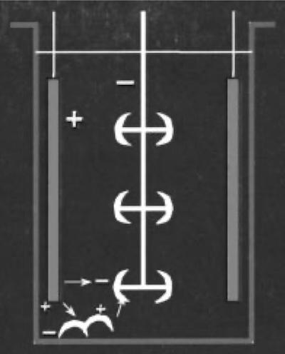 Fig. 1—Dropped parts producing a bipolar circuit.Bipolarity is particularly prevalent in plating solutions with poor conductivity, notably those containing hexavalent chromium. Many automated plating lines have a “hot” shoe and no anodes near the entry of the plating tank so that racks of parts do not enter the solution without power, creating a bi-polar condition during the short time between the first part entering the solution and the connection of power upon full entry of the rack.
Such a bipolar condition is often recognized by a dull or white deposit on the parts at the bottom of the rack, as the parts become negatively charged on the side nearest the anode but positively charged on the side farthest from the anode, resulting in a passive nickel surface.
Parts dropped into a plating tank can also yield bipolar conditions, as shown in Fig. 1. The dropped parts, located near an anode, will develop a negative charge near the anode and a positive charge farther away. That means the dropped parts may act as undesirable “auxiliary” anodes at the bottom of the tank.
Maintenance of the tank should include routine removal of dropped parts to prevent such a problem.
Stray Currents
Stray currents typically cause problems in selected parts of the tank. Look for nonuniform defects that are related to current density or reverse polarity. Because plating equipment provides service in a wet environment, there is ample opportunity for currents to stray through undesirable paths. Stray currents result from poor insulation at critical points. For example, the saddle on a tank needs to be insulated from the tank itself, especially if the tank is not lined.
Saddles that are operated under very wet conditions may introduce a stray current even though an insulator is present. Failure of these insulators will result in some amount of current traveling through the tank, yielding undesirable polarities or current densities. A similar condition is produced by mounting tanks on top of wet floors (they typically are raised off the floor on “I” beams to eliminate this possibility).
Lined tanks should be spark-tested annually to confirm the integrity of the liner. Perforated liners are sources of stray currents and can eventually lead to catastrophic leakage problems. Automated plating equipment may be operated with large motors running on alternating current. Poorly grounded equipment may send stray currents through the superstructure and into processing tanks or racks/ barrels.
A troubleshooter must be aware that conductors carrying current produce a magnetic field that can also produce currents (in places where they may not be wanted).
Hunting for stray currents can be quite a challenge. It should be left to a competent electrician or a rectifier representative, as they are familiar with the location of grounds and how to identify a stray current condition.
Rectifier/Busing Failures
While rectifiers are generally highly reliable, they can burn out a diode, or circuitry designed to filter out ripple may fail, resulting in a rectifier that is “single-phasing” or producing “high ripple.” In most cases, such failures can result in a poor appearance, especially in solutions that are sensitive to ripple.
Ripple is the amount of “leftover” AC that remains after the conversion to DC. Most high-quality rectifiers produce DC with five percent or less ripple. Although numerous solutions are not sensitive to ripple, some—especially hexavalent chromium plating solutions—are quite sensitive. Suppose high ripple is suspected and a rectifier change-out is not practical. In that case, a rectifier technician will need to put an oscilloscope on the unit to determine the level of ripple.
Busing from the rectifier(s) to the tank(s) is rarely a problem. Still, suppose the rectifier output varies significantly in voltage between the rectifier terminals and the anode/cathode bus on the tank. In that case, you should look for a bad connection, which typically runs hot. Well-designed bus connections typically do not run so hot that you cannot put your unprotected hand on one of the conductors and keep it there. If the bus runs too hot, look for a weak connection.
Safety note: To prevent hand burns in high-power systems, spray water from a squirt gun on the bus connection and look for sizzle.
Current Density/Agitation
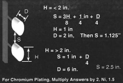 Fig. 2—Part spacing to avoid shading.While calculations can be made to predict how long to plate a part to achieve a desired thickness, Faraday did not devise a method to ensure that the thickness is uniform across the entire part. Therefore, any given part will have high-, medium-, and low-current densities during the electroplating process.
Because almost all desirable properties we seek to obtain from a plated metal are a function of current density, an effort must be made to make this parameter as uniform as possible. Parts placed too close to an anode will tend to have less uniform thickness than parts placed farther away. Shielding, proper part-spacing on racks, and anodes that are shorter than cathodes (racks) are typical measures taken to make current densities more uniform across complex shapes.
We must also realize that each contact between the rack and the part can carry only about 10 amperes during plating. Figure 2 is a guide developed by the Belke Company for proper part spacing on a rack. Note that the figure requires the application of a multiplication factor for nickel and hexavalent chromium plating.
The current density and agitation should be manipulated to work in tandem. The higher the operating current density, the higher the level of agitation in the plating tank should be.
Frank Altmayer is a Master Surface Finisher, an AESF Fellow, and the technical education director of the AESF Foundation and NASF. He owned Scientific Control Laboratories from 1986 to 2007 and has over 50 years of experience in the metal finishing industry. He received the AESF Past Presidents Award, the NAMF Award of Special Recognition, the AESF Leadership Award, the AESF Fellowship Award, the Chicago Branch AESF Geldzahler Service Award, and the NASF Award of Special Recognition.