Corrosion is an extremely crucial problem that is of concern in many different applications.
 Maria FernandezAlvarez, Cristina Hijon-Montero, Asunción Bautista, Francisco Velasco, and Danielde la FuenteThe use of organic coatings is one of the most efficient and used methods to protect metals since, in addition to being economical, they are exceptionally versatile [1]. In recent years, organic powder coatings have been increasingly used because of their important advantages with respect to conventional liquid organic coatings. Their strong point is that they have no solvents in their compositions, making them eco-friendly materials. This is of great interest due to current restrictions limiting volatile organic compounds (VOCs) in both waterbased and solvent-based products [2]. Some other advantages of these coatings are, for instance, the possibility of recovering 99 % of the powder lost during the coating process and the superior finish that this type of coating [3,4] has. In fact, it is considered to comply with the “4E principle” (environment, efficiency, ecology and economy) in the coating industry, making its development of special interest [5].
Different studies are found in the literature regarding improvement of protection given by the coatings to the metal substrates in aggressive environments. Some work has been able to obtain mechanical improvements in coatings with different types of inert reinforcements [6,7]. At the same time, other authors have focused more on manufacturing anticorrosive coatings with the addition of smart corrosion inhibitors that present different protection mechanisms when the corrosive agents appear.
Silica additions are very common in organic coatings. Silica microparticles usually act as extenders, with the advantage of being inert, and also promoting abrasion resistance. Silica particles can act as fillers, decreasing the permeability of the coatings and so affecting the corrosion behaviour of the metallic metals. The SiO2 microparticles addition to the organic coating has also proven to have a positive effect on surfaces pretreated with silanes [8].
On the other hand, it has also been shown that SiO2 nanoparticles can release SiO2ions at alkaline pH, helping to the passivation of galvanized steel [9]. Moreover, it has been recently reported that mesoporous nanosilica particles can exert an inhibitory effect against delamination [10]. As far as nanoparticles are concerned, their direct effect in metalcoating adhesion improvement and polymer crosslinking cannot be ignored [6], as well as the improvement of strength and barrier properties of coating [10]. However, the use of nanosilica as smart carriers for corrosion protection has been strongly developed in recent years, acting as reservoir for functional species (inhibitor/self-healing agent). Non-modified silica has not been considered up to now a typical corrosion inhibitor, even when particles in the nanoscale are concerned [11,12], although degradation products of silica can be expected in the alkaline environment of the delaminating interface [10].
Ion-exchanged silica are anticorrosive pigments that were already introduced in the 1980s and that can affect the corrosion by developing an essentially electrochemical active action [13]. Due to metallic cation releasing, exchanging or adsorbing on the metal surface, clear improvements in corrosion resistance have been reported [14].
In general, it can be considered that ion-exchanged silica anticorrosive pigments have become a non-toxic alternative to chromate for increasing the effectiveness of protective organic coatings. One of the corrosion inhibitors often considered in previous relevant studies for defective liquid coatings was silica calcium-ion exchanged particles. They must be considered of special interest because of their eco-friendly characteristics. The inhibition mechanism of these Ca/Si pigments is assumed to be based on the precipitation of a protective film between anodic and cathodic sites of the metal surface [13]. This film is formed when water and aggressive ions provoke the release of calcium and silicon ions and their precipitation in the interface, and its presence is assumed to hinder the ionic movements between anodic and cathodic sites. The effectiveness of this mechanism can be affected by the chemistry and morphology of the pigment particle [13].
The inhibitory properties of Ca-exchanged silica in liquid epoxy coating have been already tested and results supporting the formation of the interfacial protective silica layer reported [15,16]. The protection against corrosion is due to the formation of a calcium silicate film in the coating-metal interface, thought the additional formation of other silicates after the reaction with the metal substrate cannot be discarded [13]. The alkaline pH of the pigments, due to silica nature, also contributes to decrease the aggressivity of the media, as they would react with OHgenerated in the cathodic regions [13].
In general, many studies with ion-exchanging corrosion inhibitors can be found for other types of liquid and sol-gel coatings [16–22], but only one previous research has been found for their use in powder coatings [23].
These ion-exchange Ca-pigments were successfully used in liquid organic coatings improving their corrosion resistance with contents up to 5 wt% of particles [22], but positive results are obtained at lower concentrations. For powder coatings, the requirements of the organic powders to be electrostatically charged limits the presence of inorganic particles as in their surface.
For coatings whose electrical resistance and permeability to water and oxygen are not enough to avoid the formation of anodes and cathodes in the metal substrate, the addition of inhibitive pigments can contribute to decrease the corrosive attack. However, the degradation process for coatings with good barrier properties starts by a mechanical failure. The coating is damaged by an external agent, leaving the metal substrate exposed to the atmosphere. The inhibition of the progress of the delamination front is the key for limiting the progress of the destructive process through the material. The steel regions exposed to the environment through a defect corrode in a generalized way, whose rate can be increased by the formation of differential aeration cells as the ones often generated between the non-covered metal region and the limit of the coating on the defect. The formation of this type of cells not only causes a higher corrosion rate in the regions that become preferential anodes; their most dangerous effect is to cause the debonding of the coating and the dramatic increase of the amount metal surface exposed to corrosion. The debonding of the coatings can take place through two different mechanisms: cathodic delamination [24] or anodic undermining.
Scanning Kelvin probe (SKP) technique is an ideal tool for in situ monitoring of the degradation processes at the interface between the coating and the metal [25]. SKP is a non-contact and non-destructive technique that is used for studying atmospheric corrosion of polymeric coated metals, since it was proposed 1983 by Leidheiser and col. [26]. SKP allows obtaining information in condition where other, more traditional, electrochemical techniques are not applicable. SKP allows the delamination mechanism of the painted system to be understood, once a defect has been previously made in the coating, and the damage progresses under drops or ultra-thin electrolyte layers [27]. Moreover, using SKP, it can be obtained information about the delamination rate and how it evolves with time [6], and also identify the rate-determining step of the mechanism [28]. Though many studies have been published with interesting results using SKP in liquid organic coating systems [17,29,30], there is currently only one that examines the progress of the delamination front of powder coatings using this technique [6]. Other techniques, as electrochemical impedance spectroscopy (EIS), often used to evaluate anticorrosive properties of coatings, have shown not to be sensitive enough to monitor the electrochemical attack under the coating when starting from a defect, when thick, highly protective epoxy powder coatings are considered. In [6], there are 1-year exposure results obtained with EIS and a discussion that can help to understand in-depth this fact. A review about cathodic disbondement of organic coatings has also come to the same conclusions about the limitations of EIS for cathodic delamination studies [31].
Moreover, in order to minimize the onset of mechanical damage of the organic coatings during their in-service life, different strategies of functionalization have recently been explored to develop new protective coatings. Within powder organic coatings, different types of microparticles [32] and nanoparticles [3,33–35] have been added to improve both mechanical properties and wear resistance. Furthermore, nanoparticles can improve other properties, as UV degradation -nanosilica slow down this degradation process [36]or antibacterial properties-using nanosilver additions [37].
On the other hand, it is very important not only to add appropriate reinforcements to improve the adhesion, protective and mechanical properties of powder organic coatings, but also to obtain homogeneous mixtures, ensuring that the particles are well embedded in the polymeric resin after curing [38], since heterogeneities can even cause coating failure [39]. Furthermore, another novelty of this work is the mixing method used. Generally, researchers who have carried out studies on anticorrosive particles in powder coatings use more expensive mixing methods such as extrusion [40,41]. In this case, the mixing method used (hot mixer) requires lower temperatures and shorter mixing times than extrusion. Along these lines, recently published results about other mixes of functionalized powder coatings [42,43] have proven the ability of hot mixing to provide homogeneity in the particle distribution and good bonding with the polymeric matrix.
It is clear that, to ensure a good in-service performance under exposures in corrosive atmospheres, it is important not only to have coatings that hinder delamination of the coatings from defects due to metal corrosion under drops or thin condensed electrolyte layers, but that also to limit prior mechanical failures of the coating. Therefore, the objective of this work is to obtain a powder coating with an excellent performance in order to have a longer service life. For this, the study is focused on the improvement of the mechanical properties (hardness and scratch) and wear resistance (with reciprocating tribometer) of the coatings to delay the mechanical failure of the coating. On the other hand, it is pretended to obtain coatings that, in the event of a mechanical failure, have better corrosion resistance thanks to a decrease in their cathodic delamination, studying this mechanism with the SKP
technique. In order to achieve this goal, the effect of calcium ionexchanged silica micropigments was studied on the wear resistance and delamination of epoxy powder coatings. To do this, these pigments were added through hot-mixing in the epoxy powder, and also the feasibility of using this innovative mixing method for functionalizing powder coatings (that have previously been explored for adding nanoparticles [4,6]) was studied for particles with bigger size, as the tested corrosion inhibitors.
Materials and Methods
Manufacturing of organic coatings
An epoxy powder coating provided by Cubson International (Humanes de Madrid, Spain) was used to manufacture different organic coatings. The composition of this epoxy powder coating also contains pigments such as TiO2 (2 wt%) and additives like dolomite (24 wt%) and talc (14 wt%). The Shieldex C 303 particles used (W.R. Grace & Co.Conn., USA) are non-toxic and anticorrosive pigments, which are calcium ion-exchanged, synthetic amorphous silica. These anticorrosive pigments have particle sizes ranging from 1 to 10 μm, with a D50 of 3.6 μm. Fig. 1 shows the morphology of the micropigments and their particle size distribution.
The epoxy powder coating and the anticorrosive pigments were mixed through a hot mixer Haake Rheocord 252p (Thermo Fisher Scientific Inc., USA) for 15 min at 72.0 ± 0.5 ◦C, at 40 rpm and under dry conditions. Three different organic coatings were studied: the commercial as received epoxy coating (labeled as EP), the EP passed through the hot mixer (labeled as 0 %) and the hot mixed coating with 3 % (by wt.) anticorrosive micropigments. If pigments in amounts higher than 3% were added to the epoxy powders, the electrostatic gun started showing charge limitations that affected the final quality of the organic coatings.
In liquid coatings, other authors have determined additions up to 6.5% [15] or 10 % [44] as being optimum. However, for the epoxy powder under study and the electrostatic method that must be employed, amounts higher than 3 % in the mix start to hinder the powder application.
Once the powder coatings and the pigments were mixed, the materials were deposited on degreased carbon steel sheets, using a COLO900 T control unit, with a voltage source of 100 kV and a COLO-07 electrostatic spray gun (COLO, China). After the coating process and according to the manufacturer, the coatings were cured for 15 min at 180 ◦C. The thicknesses of the coatings were about 60–70 μm.
To evaluate the effect of the microparticles on the curing of the epoxy powder, a kinetic study was performed. Differential scanning calorimeter (DSC) equipment, model 822 (Mettler Toledo GmbH, Switzerland), was used for the three organic powders under study. The tests were carried out in the range of 25–250 ◦C, using aluminum crucibles (capacity of 40 μl) and with nitrogen as purge gas (flow of 35 ml⋅min-1). The epoxy sample weight was 10.4 ± 0.1 mg. To calculate the activation energy (Ea) of the curing reaction of each organic powder, two methods were performed: the Kissinger and the Model Free Kinetics (MFK) methods. As both methods require testing at three different heating rates for the calculation of Ea, tests on each powder were carried out at 5, 10 and 20 ◦C⋅min-1. The Kissinger method [45] allows the constant Ea of the curing process to be known and was calculated with Eq. (1), where Tp is the peak of the curing curve, β is the heating rate, R is the gas constant, and C is a constant.
ln(β/T2p ) = -Ea/RTp + C (1)
On the other hand, the MFK method [46,47] supposes an Ea that varies with the curing degree (α) of the resin and was calculated with the STARe software (Mettler Toledo GmbH, Switzerland). This method allows simulate reliable predictions about conversions of reactions and calculate the Ea [48], being based on Vyazovkin and Wight assumptions [49] Its fundamental assumption is that the reaction model f(α) is not dependent on temperature or heating rate.
Characterization of organic coatings
Universal hardness (HU) was measured with a ZHU 2.5 universal hardness tester (Zwick Roell, Germany), and a Vickers pyramidal diamond indenter was employed. At least nine measurements were performed on each coating. The conditions applied were a load of 5 N and a load application speed of 1 mm⋅min-1.
Scratch resistance tests were carried out in order to evaluate the adherence between the epoxy coating and the carbon steel substrate. For this purpose, an Elcometer 3000 Clem Unit (Elcometer, UK) was used. The scratch test was performed under a mass of 5 kg. Image-Pro Plus 5.0 software was used in order to evaluate the scratched area in each coating. The ratio between the delaminated area and the length of the scratch was represented. A minimum of eight measurements were carried out in each epoxy-based coating.
To evaluate the delamination resistance, the scanning Kelvin probe (SKP) was used to study the delamination of each coating. SKP is a nondestructive and non-contact technique for measuring the potential between the sample (working electrode) and the reference electrode [50]. The equipment used was a Height-Regulating Scanning Kelvin Probe (HR-SKP) from Wicinski & Wicinski GmbH (Germany). This system maintains a constant tip–sample distance. A flat-ended cylindrical Ni/Cr (Ni80/Cr20, Goodfellow, UK) probe with a diameter of 50 μm was used as the needle, which was moved by means of three stepping motors for X, Y, and Z directions. Before measuring, the Kelvin probe was calibrated using a standard Cu/CuSO4 solution in order to establish a relation between the work function and corrosion potential. SKP potentials are given relative to the potential of the Standard Hydrogen Electrode (SHE) [51].
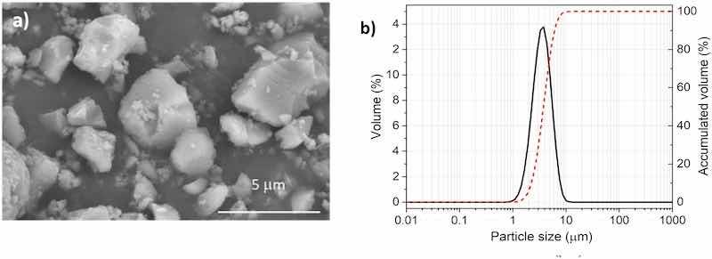
Fig. 1. a) Morphology and b) particle size distribution of micropigments used.
The size of the tested sample was 3 × 2 cm2 and the mechanical defect in the organic coating was 1 × 2 cm2. An electrolyte reservoir was performed with an adhesive resin around the defect in order to place the 3.5 % NaCl drop. All the scans were performed stepwise and were fully automated. The scanned area was 3000 × 500 μm2 with a step of 50 μm in both X and Y directions, and the speed was set at 5 μm/s. All measurements were carried out in a humid environment with 99 % RH and at 25 ◦C. Before the measurements, the samples were placed in the chamber for 24 h. The delamination front of the coatings was studied for 26 days, obtaining SKP profiles also at intermediate days (1, 6, 8, 12, and 19 days) after the depositing the 3.5 % NaCl drop. Four scans to obtain several SKP profiles were performed for each coating and each day studied. Finally, the delamination front of each coating was calculated taking into account the criterion established in previous studies [52]. Cathodic delamination errors have been calculated as the standard deviation of each scan performed for each coating and each day. After performing the SKP measurements, the samples were storage in an inner atmosphere with RH about 45 % and then immersed in 65 % HNO3 for 80 s. Just after acid immersion the formed rust and organic coating that become detached from the metal substrate due to the acid cleaning were carefully eliminated.
Moreover, another electrochemical analysis were carried out on coated samples, on which a defect was created. All defects were created with a standardized tool, showing an average area of 1.7 ± 0.5 mm2. The area was measured with an optoelectronic microscope (Olympus Corporation, Japan), to normalize the electrochemical parameters on each different coating. A 4.6 cm diameter polymethylmethacrylate tube was adhesively bonded to the coating to limit the testing area. A 3.5 % NaCl solution was used. Electrochemical impedance spectroscopy (EIS) measurements were carried out using a Gamry 600+ potentiostat (Gamry Instruments, USA). A three-electrode cell was always employed. A saturated calomel electrode (SCE) was the reference electrode, a graphite bar was the counter electrode, and the defective steel coated samples acted as working electrode. The study was carried out at open circuit potential (OCP) with a signal amplitude of 10 mVrms. Frequency ranges were 105 to 5⋅10-3 Hz. Samples were tested for 35 days. The subsequent analysis of EIS spectra was performed with the ZView4 software (Scribner Associates).
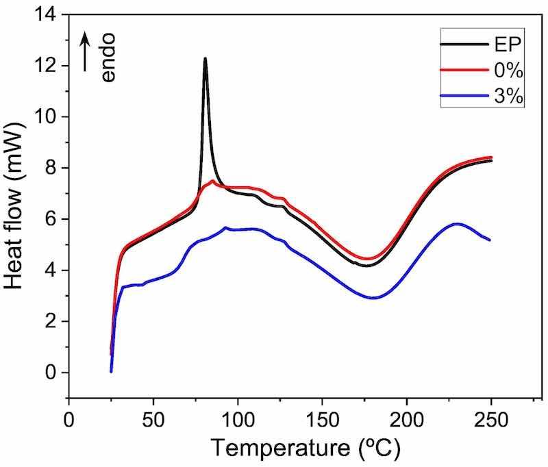
Fig. 2. DSC curves of the three epoxy-powders measured at 20 ◦C⋅min-1
Polarization curves were also carried out the days 1 (obviously, this sample was then discarded and not used for EIS) and 35. The same cell configuration, electrolyte and equipment used for the EIS measurement were used for the polarization curves. Voltages were swept from -0.2 V to 0.2 V (always vs OCP), and scan rate was 0.5 mV/s.
The wear resistance was studied for all organic coatings. An UMT Tribolab reciprocated tribometer (Bruker Optik GmbH, USA) was used at room temperature and under dry conditions. Four experiments were carried out on each organic coating and the conditions were: 10 Hz frequency, 5 mm amplitude, a time of 10 min and a 5 N load applied. The coefficient of friction (COF) was also measured during each wear test. Average depth and width of wear tracks were measured (nine values were taken in each wear track) with the optoelectronic microscope. The wear mechanism of each organic coating was also evaluated with scanning electron microscopy (SEM), under a Teneo-LoVac equipment (Thermo Fisher Scientific Inc., USA).
Results and Discussion
The possible effect of microparticles on the curing kinetics of the epoxy powder is the first important aspect to analyze. Powder samples were analyzed with DSC after the hot mixing process. Fig. 2 shows examples of DSC curves for the three powders studied. In all the curves, an exothermic peak related to curing can be appreciated. During this stage, the crosslinking of the epoxy resin takes place. In the case of plotted curves, when the heating rate is 20 ◦C⋅min-1, the curing peak starts at approximately 110 ◦C, finishing at 230 ◦C. At first sight, it seems that the curing is somewhat similar for the three materials. The main difference found is the presence of an endothermic peak at around 80 ◦C in the EP material, that is, in the only material that has not been passed through the hot mixer (Fig. 2). This peak could correspond with the relaxation enthalpy of the polymer, a common phenomenon in polymers, which has been previously seen for epoxy powder coatings with nanoparticles [38,42]. The fact that the other two powders (0 % and 3 %) do not show this peak can be easily explained. As the hot mixing process was carried out at 72 ◦C, the heat input during mixing has been able to relax the stresses in the as-manufactured powder, thus provoking the disappearance of this endothermic peak in the DSC curves.
Moreover, a deeper analysis of DSC results can be carried out through the Kissinger and MFK methods. These methods allow the activation energy (Ea) of the curing process to be calculated. Table 1 shows the calculated values for the three epoxy-based powders. First, it has to be pointed out that the differences in Ea values between both methods clearly depend on their specific assumptions. On one hand, the Kissinger method supposes a first order curing reaction during the whole process to calculate a constant curing Ea, using Eq. (1), with plots as those shown in Supplementary Material (Fig. S1). On the other hand, the MFK method assumes a varying Ea with the curing degree, without defining a specific order of the reaction model, taking into account the influence of heating rate on curing reaction and of the latter on Ea (Supplementary Material, Figs. S2 and S3) [42].
As can be clearly seen (Table 1), Ea of unloaded powders (EP and 0%) are very similar, as could be expected. This shows that the hot mixing process carried out has not affected the curing process of the resin, and the temperature was kept low enough to avoid any partial curing or modification of the original epoxy powder. However, the material with added microparticles (3 %) clearly presents higher Ea values than the other two powders (Table 1). As the resin has not been affected by the hot mixing method (as indicated when comparing EP to 0 %), the only reason is the presence of the microparticles, which must slightly hamper the curing process. Possible reasons for this effect could be an increase in the viscosity of the resin during the curing process due to microparticles, or a hindering of the diffusion of species when crosslinking takes place, among others. The presence of hydroxyl functional groups on the surface of the added pigments has been reported [13]. Any acidic group existing in the epoxy resin can lead to acid-base interactions with micropigments, instability of viscosity and a reduction in the curing rate [13].
Table 1: Ea (kJ/mol) of the curing process of epoxy powders, obtained through the Kissinger and MFK methods from DSC data. Curing time (min) for a 99 % curing degree at 180 ◦C calculated from the MFK method.
| Method | EP | 0 % | 3 % | |
| E (kJ/mol) | Kissinger | 69.7 | 69.0 | 72.2 |
| E (kJ/mol) | MFK | 73.2 | 72.9 | 83.9 |
| t (min) | 5.8 | 5.7 | 8.8 |
Moreover, the MFK method is able to simulate the time required for curing at a fixed temperature. Accordingly, the changes of Ea can be taken into account for the real curing process. As the manufacturer conditions for curing are 180 ◦C, this temperature was selected for calculating the curing times in Table 1. These tabulated times are the ones required for 99 % curing of each coating at this temperature. Obviously, the values are consistent with Ea analysis (Table 1): very similar for EP and 0 % resins, and somewhat higher for 3 %. However, the typical curing conditions for EP suggested by the manufacturer are 15 min. That is, the addition of the micropigments affects the curing process in such a moderate way that it is not necessary to modify the traditional parameters for the industrial curing of the epoxy powder.
Once the coatings were cured, the hardness was measured (Fig. 3). The achieved hardness is indicative of an adequate curing process, and the differences in hardness between EP and 0 % are plainly negligible, as could be expected from the DSC results (Fig. 2, Table 1). Average hardness results of 3 % coating are slightly higher than unloaded coatings. This indicates that not only has the epoxy resin cured properly, as there is no hardness reduction in spite of the Ea decrease and the no change in the curing, but also that some beneficial effect could have been generated due to the presence of microparticles. The ceramic nature of the amorphous silica microparticles could be responsible for this suggested slight increase (although error bars overlap in Fig. 3). However, this increase is not as big as that found in studies with other silica nanoparticles [43], whose smaller size very effectively limits the sliding and movement of the polymer chains, and significantly increases the hardness and stiffness of the coatings. The present results are consistent with other research using microadditions. For instance, CaCO3 microcontainers on epoxy coating, in the same amount and with a similar sieve size, do not change the hardness of the coating [53], although the pencil method is used and this technique is not as accurate as microhardness for detecting small differences. The addition of 6 % SiC microparticles to an epoxy resin only slightly increased the Shore D hardness of the material [54].
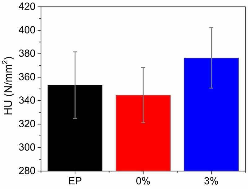
Fig. 3. Universal hardness (HU) results for the surface of the three organic coatings.
The adhesion of the developed organic coatings to the steel substrate was likewise measured. Results are shown in Fig. 4a. The data reflect the delaminated area during the scratch test (Fig. 4b); thus, higher values imply lower adhesion. As expected, all the coatings behave in a very similar manner; but there is a slight trend for the 3 % to delaminate less. A naked-eye comparison among scratches seems to show slightly wider scratches on coatings without micropigments (EP and 0 %), with more straight boundaries, while somewhat narrower scratches on 3 % are more irregular (Fig. 4b). The observed increase in hardness caused by the additions (Fig. 3) can be responsible for lower crack propagation and delamination when the scratches are made.
The SKP measurements allow the potential in each part of the coated system to be measured: in the metal, under the intact coating and in the metal-coating interface. In this way, it is possible to understand the debonding mechanism of the coating and quantify the damage. Fig. 5 shows the SKP profiles (the distance from the defect made in the coating vs the potential) of the coatings under study at days 1, 8 and 26, as an example. The delamination front of the curves on day 26 has been marked with a red cross. First, the SKP profiles obtained for all the epoxy coatings are similar to those obtained for another steel protected with other coatings in similar conditions [6,55]. In the defect area, low potential values, typical from anodic regions, are detected. High potentials with stable values monitored at a certain distance correspond to regions of intact coating well bonded to the substrate. Intermediate potentials values allow the identification of regions where the cathodic reactions are located. This type of profiles suggests that a cathodic delamination mechanism is occurring in the metal-coating system [6,56]. In all cases, the SKP profiles start at low potentials, corresponding to the defect, and therefore to the metal (anodic behaviour). Then, it is observed how the potential increases, up to values practically of 0 mV potential, which corresponds to the intact metal under the adhered organic coating. The intermediate zone between the anodic behaviour and the intact coating relates to the cathodic activity that promotes the loss of adherence of the coating with the metal.
The delamination front is identified with the midpoint between the anode and the intact coating. To do this, the first derivative of each curve is calculated, as described in other previous work [51,57]. In Fig. 6, the delamination front values of the three epoxy coatings at the different times can be observed. The coating containing microparticles clearly has the lowest delamination rate. During the first 6 days of measurement, there are practically no differences between the cathodic delamination of the epoxy coatings. However, as of day 8, the coatings without microparticles experience an increase in their delamination rate, while the 3 % displays a slow progression of the delamination attack. In fact, in the 3 % coating, the delamination is practically constant throughout the test. The microparticles manage to hinder this delamination mechanism considerably. At day 26, the cathodic delamination is three times smaller in the 3 % coating than in the EP coating.
In studies carried out with thin coatings [58,59], it has been observed that non-inhibited systems have a cathodic delamination process only controlled by the diffusion of Na+ cations, which advance from the electrolyte (drop) to the cathodic region. In this way, the large local increase of OHin that cathodic region causes a debonding of the coating with the metal [60] in the absence of pigments. However, for thicker coatings with low permeability like the ones considered in this study, the phenomenon is more complex [6] and the influence of oxygen diffusion through epoxy coating in environments with high relative humidity cannot be disregarded.
One of the strategies that can be used to hinder the progress of the cathodic delamination is the presence of a poorly conductive layer at the coating/substrate interface [24]. Previous studies have suggested that these pigments effectively delay the progress of the delamination front from a defect [13,16]. Under corrosive exposure conditions, water and aggressive ions provoke the release of metal ions (Ca2+) and soluble silica from the micropigment particles. They migrate to the steel-coating interface, the area under study with the SKP test, possibly being able to find Si enrichment on the interface, forming a protective silicate film on the steel surface [16,23,44]. For coatings with this type of pigments, EIS results compatible with the formation of film in the coating-metal interface at a slow rate can be found in the literature [15]. This film is proposed to hinder the migration of Fe2+ cations from the anode, slowing down the strength of the corrosion cell. At the same time, the negative charge of the micropigments suggested in the literature [16] can reduce the migration of the chlorides to the anodes, lessening the contribution of this ion-concentration cell to the development of the attack. Moreover, when the progress of the attack is based on the cathodic delamination caused by OH(as it is the case), the presence of a calcium silicate layer in the interphase [15,16] can partly neutralize local alkaline pH and reduce the rate of coating debonding.
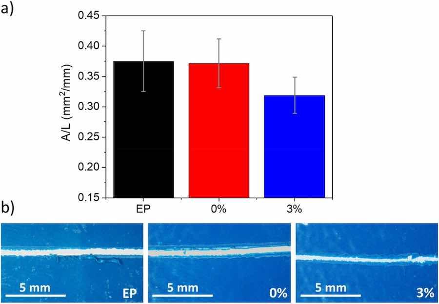
Fig. 4. a) Adherence (delaminated area by unit length) of the three organic coatings to the carbon steel substrate determined using the scratch test. b) Examples of scratches made on coatings.
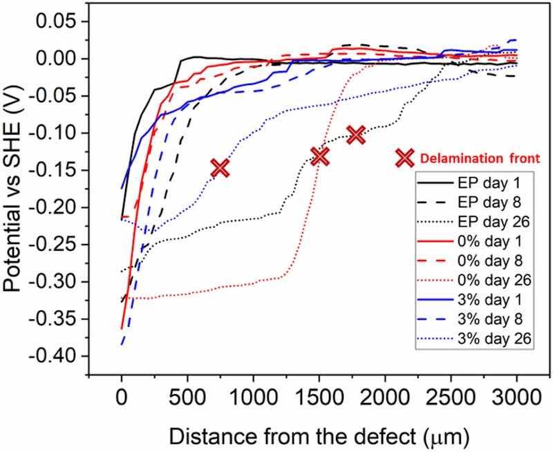
Fig. 5. SKP potential profiles of the three organic coatings (days 1, 8 and 26).
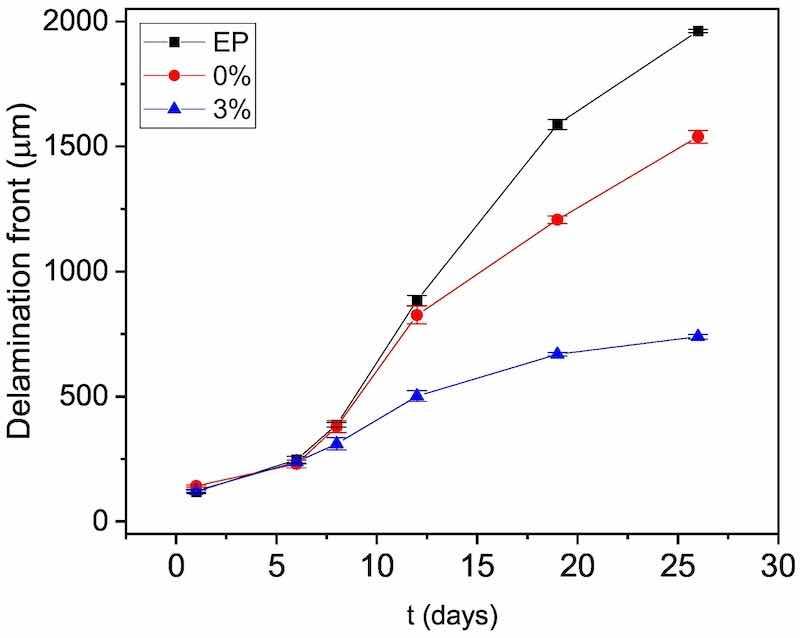
Fig. 6. Progress of delamination front from the defect obtained through the SKP measurements carried out for the three organic coatings studied.
Hence, the positive effect of the tested ion-exchanged pigments has been proved for the hindering of the progress of the attack from a defective epoxy powder coating when they have previously been added by hot-mixing. It can be related to synergistic effect of the presence of calcium and silica, as it has been traditionally assumed [15,16,21]. However, the obtained results do not allow to deepen more into this mechanism up to the point of concluding with confidence what would have occurred if pristine mesoporous silica containers would have been added. Previous results about the effects of pristine silica have been reported only for mesoporous, nanometric silica particles and have been positive for Zn surfaces, but not for steel [10]. In our research, micrometric silica (that would be less reactive than nanometric) is considered, and iron silicates, if formed, are considered non-protective [10].
Moreover, though the exchange ability of this pigment in media with high amounts of chlorides is very limited and has been questioned by some authors [16], it has been demonstrated that Na+ ions of the medium (relevant for the development of the cathodic delamination process) are exchanged by calcium ions [44]. However, basic further research about the mechanism of this pigment to control the cathodic debonding, once the practical interest of the coating has been demonstrated, will become clearly interesting.
In Fig. 7, it can be seen the visual aspect of each type of coating (in blue) under study after the SKP testing and the nitric acid cleaning of the oxides. It is obvious that the coating detachment taking place in the coating functionalized with 3 % silica exchange pigments is much lower and that the additions have been clearly efficient for delaying the progress of the attack by cathodic delamination.
The relevance and sensitivity of SKP measurements for monitoring the cathodic debonding and the progress of the corrosive attack for highresistive, defective coatings were checked through a parallel study with EIS and polarization curves. After the EIS and polarization tests, coating detachment was intended using the same conditions than those used for obtaining the images in Fig. 7, and even also other ones slightly more aggressive, but no debonding of the coating have been observed after a very careful visual exam. This result proves that the coating degradation mechanism is highly determined by the specific exposure conditions to NaCl solution. The studies carried out under droplets, simulating atmospheric corrosion attack, which are the ones SKP tests replays, favour the location of preferential cathodes and clear cathodic debonding of the coatings in less than 30 days (Fig. 7). Fully immersion in NaCl solution, which is the condition where the EIS and polarization tests were carried out, modifies the oxygen access and affects the cathode distribution, which has clearly changed for the coating under study, and the degradation mechanism.
In Fig. 8, the time evolution of the EIS spectra of the samples can be observed. The three coatings under study exhibit a similar performance. The experimental spectra obtained prove a clear decrease of the lowfrequency impedance for all the cases, being the magnitude of the impedances at low frequency very similar for identical exposure times.
The experimental impedance data can be properly simulated using a Randles circuit with a Warburg element (W), that is to say, a Rs(CPEdlRt(W) circuit. CPEdl and Rt are used to simulate the capacitive behaviour of the double layer and charge-transfer resistance and W the contribution of the diffusion stage to the kinetics. The quality of the fitting obtained using this equivalent circuit can be easily checked in Fig. 8. This equivalent circuit is typical of uncoated corroding steel and informs that the electrochemical response of the systems corresponds to that of the bare steel surface exposed directly to the solution through the small defect.
In Fig. 9, the resistance values obtained for the fitting, which are key points for estimating the kinetics of the processes, are plotted. It can be seen that the resistance associated to diffusion (Rw) is the one that control the process, as it is expected for steel immersed in a still electrolyte with high salinity (and low oxygen solubility).
In Fig. 10, results of destructive polarization tests are shown for the same exposure conditions used for EIS (Fig. 8). It can be seen that, for all the cases, there exists a clear control of the kinetics of the process by diffusion. The corrosion rate (icorr) is determined by the cathodic process, confirming the conclusions drawn for the simulation of the EIS data (Fig. 9).
The numerical results obtained from the analysis of the polarization curves can be seen in Table 2. The results from the dc potentiodynamic tests are coherent with those obtained from the ac ones: the corrosion rates (icorr) are similar for all the defective systems for the same immersion time, and the icorr of all the systems increases as the exposure is extended. The increase on the corrosion potential (Ecorr) is also coherent with an increase of the icorr in processes with kinetics determined by the cathodic process.
It can be seen that, for high-resistive coatings, traditional electrochemical techniques as EIS or potentiodynamic curves are unable to offer information about the delamination that progresses from the defect, at least in moderate exposure periods, and to explain phenomena such as that shown in Fig. 7, that occurs under droplets. The limitation of techniques as EIS for obtaining information regarding processes taking place under resistive epoxy coatings have also been recently discussed in a different publication [6]. Moreover, the modification of oxygen distribution that takes place under fully immersion condition in comparison to atmospheric exposures, is another reason of the clear limitations of traditional electrochemical methods for studying delamination under coatings such the ones considered in this study with high resistivity (able to hide the electrochemical response of the metal surface in the delaminated region) [6,31]. A transmission line model has been previously proposed to simulate the high attenuation of the electrochemical response and the shift of the contribution of cathodes under the coating to the frequencies lower than those experimentally considered for EIS corrosion studies. Hence, information obtained with EIS and polarization curves essentially correspond to the exposed metal surface and, in cases as the ones under study, it is mandatory to resort to techniques as SKP to be able to quantify the progress of the cathodic delamination. Moreover, under full immersion, the degradation mechanism of these type of coatings can change and become anodic [6] unlike that occurring under drops (Fig. 5) as the oxygen diffusion, that has been proved to be the rate controlling step (Figs. 9 and 10), can obviously be affected by the thickness and extent of the coverage of the electrolyte.
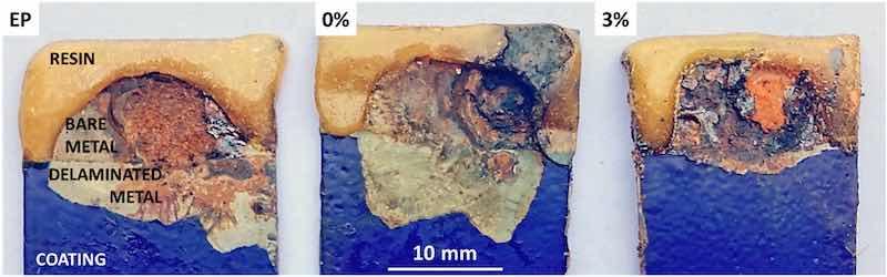
Fig. 7. Images of the samples after SKP measurements and further HNO3 cleaning.
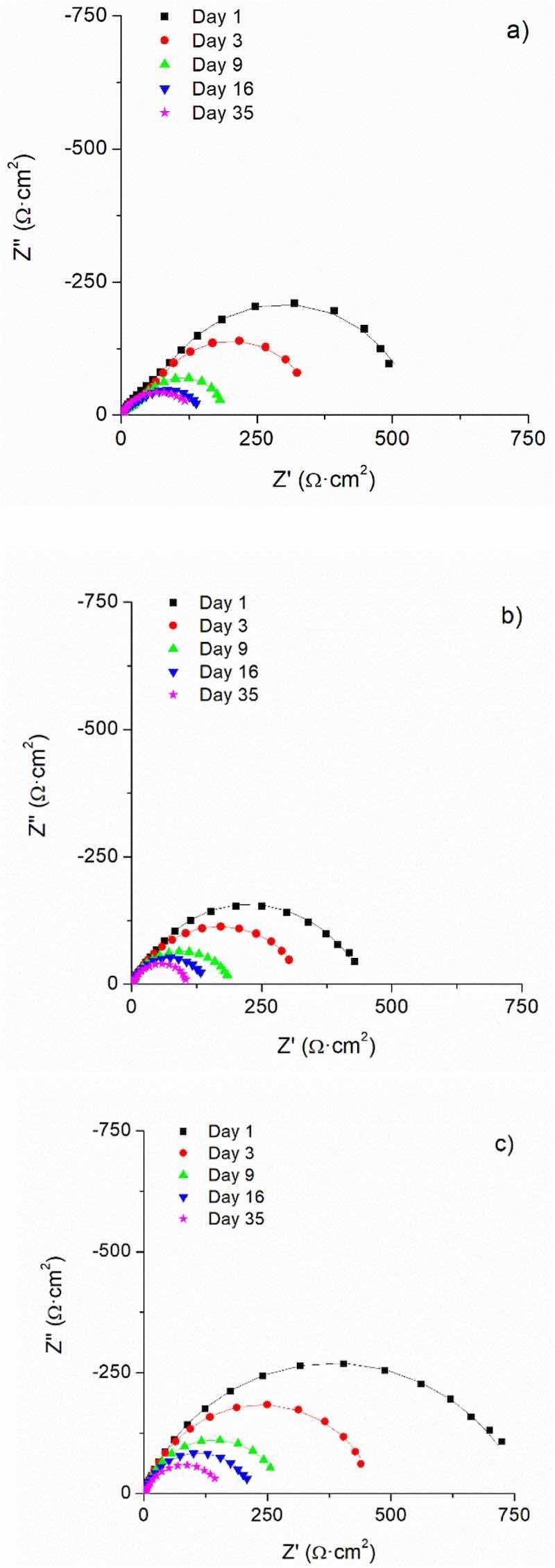
Fig. 8. Time evolution of the EIS spectra measured on defective coatings fully immersed in 3.5 % NaCl solution: a) EP; b) 0 %; c) 3 %. Experimental data are plotted with symbols and the fitted data with lines.
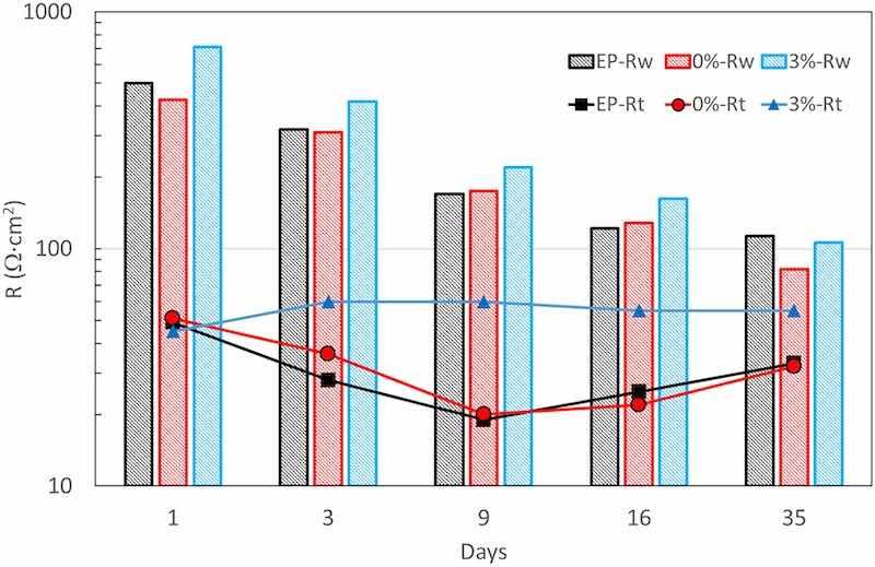
Fig. 9. Resistances obtained from the fitting of the experimental EIS data.
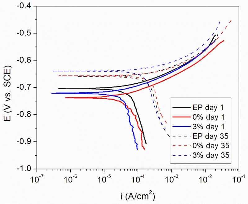
Fig. 10. Polarization curves of the defective systems under study after 1 and 35 days of immersion in 3.5 % NaCl solution.
Table 2: Numerical parameters obtained from the analysis of the polarization curves.
| Day | Ecorr (mV vs SCE) | icorr (mA/cm2) | |
| EP | 1 | -705 | 0.06 |
| EP | 35 | -655 | 0.21 |
| 0 % | 1 | -740 | 0.06 |
| 0 % | 35 | -655 | 0.22 |
| 3 % | 1 | -720 | 0.04 |
| 3 % | 35 | -640 | 0.14 |
The results obtained in this research by SKP shows the lower delamination of the innovative epoxies formulated. This would allow that, if the organic coating suffers a mechanical damage, the development of the corrosive attack and further exposure of a higher amount of metal surface would be hindered by the slower progress of the polarization front. Fig. 11 shows images of the wear tracks obtained with the optoelectronic microscope. The green parts of the image in each case correspond to the intact epoxy coating, whereas the wear tracks correspond to the blue zones. As expected, hardly any differences can be found between EP and 0 %. The fact that both materials cure in the same manner (Fig. 2) and develop a similar hardness (Fig. 3) and scratch resistance (Fig. 4) clearly explain that the tracks are similar, as is their depth distribution (violet areas). In fact, when measuring both width and depth of tracks, the results are nearly the same (Fig. 12), as could be expected. The material with microparticles (3 %), on the other hand, presents narrower wear tracks (Fig. 11), but its lower depth is more significant. Violet zones, pertaining to the deepest areas, are not found at all in the 3 % material, clearly indicating that the tracks are also shallower. After measuring the depth and width of 3 % wear tracks (Fig. 12), those values are smaller than both unloaded epoxy coatings. Hence, the 3 % has the best wear performance among the materials studied.
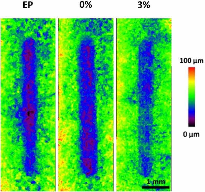
Fig. 11. Optoelectronic images corresponding to the tracks generated by the wear tests on the three studied organic coatings.
The evolution of COF during the wear test can be seen in Fig. 13. Typically, this type of coating shows a time evolution in three stages that can be observed during the wear test: a) a sliding stage, with constant and low COF; b) the start of wear, characterized by the increase of COF; and c) the development of wear in a well-defined track, characterized by high, almost constant COF [61]. The effect of the micropigments is clear in the formation step of the track. For the 3 %, the initial sliding stage cannot be observed during the tests, unlike what occurs for EP and 0 %. This fact suggests that the micropigments could become detached from the surface of the coating from the very beginning of the test. The particles would initially act as a third body contributing to an early onset of the formation of the wear track. However, the COF results suggest that the effect of the pigments is not clearly adverse, since, although the second stage starts earlier for the 3 %, it ends later. The formation of well-defined wear tracks is slower in the presence of micropigments, as they could also form a discontinuous, hard barrier between the steel ball countermaterial and the coating. Hence, the pigments could delay the progression of the wear, as it has been shown in the results in Figs. 11 and 12.
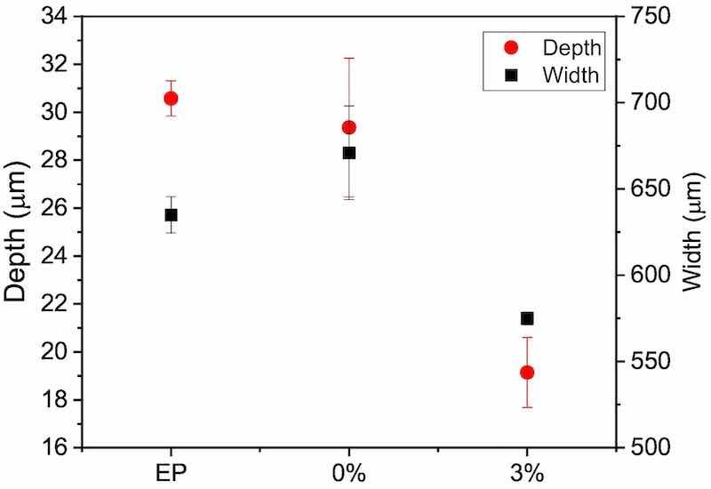
Fig. 12. Depth and width of wear tracks of the three organic coatings studied after the wear tests, obtained from optoelectronic characterizations as those shown in Fig. 11.
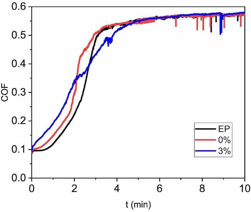
Fig. 13. Examples of COF evolution with sliding time during the wear test of the three organic coatings studied.
The SEM observations of wear tracks (Fig. 14) can provide a better understanding of the role of the micropigments in the wear of these organic coatings. EP and 0 % organic coatings show a well-defined wear track (in accordance with Fig. 11). The back and forth reciprocal movement during the test has created a very slight accumulation of worn material al the tip of the track, indicating that removed material has formed debris that is non-bonded to the track. Additionally, transverse cracks can be clearly seen in the wear tracks (marked with yellow arrows). These transverse cracks could be related to tensile loadings during the reciprocal wear test [62], as the high stable COF of the coatings (0.57 as can be seen in Fig. 13) suggests. Nevertheless, fatigue cracking (related to change of direction of movement) [63] cannot be discarded.
On the other hand, the 3 % powder organic coating shows less damage than the other two coatings at low magnifications (Fig. 14); although scratches, typical of abrasive wear, can still be seen, they are much less numerous and smaller in size.
The surfaces of the as-manufactured coatings at higher magnifications can be seen in Fig. 15a and b, and the worn surface of the coatings (Fig. 15c and d) at the same magnification is also shown. The addition of silica micropigments increases the amount of inorganic fillers in the coating as can be seen when comparing Fig. 15a with b. Bearing in mind the size of the micropigments (Fig. 1), it is clear that additions essentially contribute to increase the fraction of inorganic fillers of the coating with the biggest sizes [6,36,43]. The micropigments cannot be distinguished with confidence from other fillers of the commercial powder, as calcium silicate (talc) is present among these fillers.
After the wear tests (Fig. 15c and d), the wear reduces the amount of particles that can be seen in the surface, especially those big ones that are compatible with silica micropigments (compare Fig. 15b with d).
The sliding stress on the ceramic particles causes the wear of their surfaces (that causes their loss of material), but also the detachment from the epoxy matrix, or the breakage of some of them (bearing in mind that their nature must be essentially brittle). The detached particles and the pieces of the worn/broken ones can be re-embedded in the epoxy after being pulled along by the countermaterial ball. This phenomenon will explain the white trails in 3 % wear track (enriched in inorganic particles) that can be seen in the lowest, right image in Fig. 14. The nature and structure of the pigments can make them more prone to be broken than other ceramic fillers present in the commercial epoxy powder.
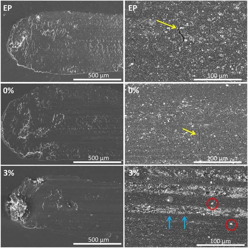
Fig. 14. SEM micrographs showing the wear mechanism of the three tested organic coatings.
The progress of small initial cracks through the epoxy matrix can be effectively hindered by the higher amount of bigger ceramic particles in 3 % coatings than in the two other coatings under study. Moreover, when the cracks develop, the higher amount of broken particles contributes to fill them, improving the withstanding of the stress distribution caused by the countermaterial. Debris filled cracks are easily observed (marked with blue arrows) in Figs. 14 and 15d.
The white trails inside the wear track correspond to the surface regions that support, at this moment of the test, the wear loads. In Fig. 14, it can be checked that between this debris enriched regions, other darker trails with big particles (marked with red circles) that cannot be identified in the white trails exist. The darker trails correspond to regions of the surface the countermaterial has not worn yet, and the particles that can be identified with pigments are not broken and transformed in white finer debris. The protective effect of the broken pigments provides a better understanding of the slower track definition (second stage of COF evolution) observed for 3 % in Fig. 13 and justifies the good results for this material in Figs. 11 and 12.
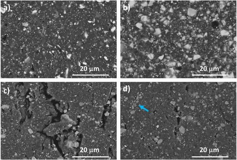
Fig. 15. High-magnification SEM images of the surfaces of the 0 % and 3 % coatings (images corresponding to EP coatings are not included for being almost identical to those corresponding to 0 % coatings: a) 0 % surface before being worn; b) 3 % surface before being worn; c) 0 % surface inside the wear track; d) 3 % surface corresponding to the white trails inside the wear tracks.
Conclusions
The main conclusion that can be drawn from the results obtained is that the addition of calcium-exchanged silica micropigments can be a good option for increasing the durability of epoxy powder coatings in aggressive exposure conditions. This conclusion is based on the following experimental results:
- The addition of 3 % (by wt.) of amorphous silica micropigments does not meaningfully affect the curing process of the selected epoxy powder coating, maintaining or even slightly increasing its hardness and adherence to the steel substrate.
- The calcium ion-exchanged silica micropigments added to the epoxy coating by hot mixing are able to delay the detachment of the coating from a mechanical defect when the coating is exposed to drops of NaCl solution.
- The wear resistance of epoxy powder organic coating with 3 % micropigments is better than neat epoxy resins, with the depth of wear track being reduced by a third under the tested conditions. The detachment and/or fragmentation of the micropigments into particles filling the scratches and covering the contact surface, that helps to better withstanding loads during the wear test and explains the increased wear performance.
- Fully-immersion in 3.5 NaCl solutions affects the development of delamination process, being demonstrated that takes place under the droplets used to simulate atmospheric corrosion.
Written by Maria FernandezAlvareza,b, Cristina Hijon-Monteroa, Asunción Bautistaa, Francisco Velascoa, Danielde la Fuentec
a Department of Materials Science and Engineering, IAAB, Universidad Carlos III de Madrid, Avda. Universidad 30, 28911 Legan´es, Madrid, Spain; b Electroceramic Department, Instituto de Cera´mica y Vidrio (ICV-CSIC), Kelsen 5, 28049 Madrid, Spain; c National Centre for Metallurgical Research (CENIM-CSIC), Avda. Gregorio del Amo 8, 28040 Madrid, Spain
Declaration of competing interest: The authors declare that they have no known competing financial interests or personal relationships that could have appeared to influence the work reported in this paper.
Acknowledgments: The authors acknowledge financial support from the European Union‘s Horizon 2020 research and innovation program through grant agreement No 766437 (ESSIAL project).
References
[1] A. Cambruzzi, S. Rossi, F. Deflorian, Reduction on protective properties of organic coatings produced by abrasive particles, Wear 258 (2005) 1696–1705, https://doi. org/10.1016/j.wear.2004.11.023.
[2] D. Czachor-Jadacka, B. Pilch-Pitera, Progress in development of UV curable powder coatings, Prog. Org. Coat. 158 (2021), 106355, https://doi.org/10.1016/j. porgcoat.2021.106355.
[3] I. Stojanovic, V. Sˇimunovi´c, V. Alar, F. Kapor, Experimental evaluation of polyester and epoxy-polyester powder coatings in aggressive media, Coatings 8 (2018) 98, https://doi.org/10.3390/coatings8030098.
[4] M. Ferna´ndez-A´lvarez, F. Velasco, A. Bautista, F.C.M. Lobo, E.M. Fernandes, R. L. Reis, Manufacturing and characterization of coatings from polyamide powders functionalized with nanosilica, Polymers 12 (2020) 2298, https://doi.org/ 10.3390/polym12102298.
[5] C.X. Wang, Y.Y. Han, W. Wang, J. Liu, N. Wang, B.R. Hou, Polyvinyl chloride/ epoxy double layer powder coating enhances coating adhesion and anticorrosion protection of substrate, Prog. Org. Coat. 158 (2021), 106335, https://doi.org/ 10.1016/j.porgcoat.2021.106335.
[6] M. Ferna´ndez-A´lvarez, F. Velasco, A. Bautista, Y. Gonzalez-Garcia, B. Galiana, Corrosion protection in chloride environments of nanosilica containing epoxy powder coatings with defects, J. Electrochem. Soc. 167 (2020) 1–25, 10.101610.1149/1945-7111/abd003.
[7] S.J. García, J. Suay, Epoxy powder clearcoats used for anticorrosive purposes cured with ytterbium III trifluoromethanesulfonate, Corrosion 63 (2007) 379–390, https://doi.org/10.5006/1.3278391.
[8] M.F. Montemor, A.M. Cabral, M.L. Zheludkevich, M.G.S. Ferreira, The corrosion resistance of hot dip galvanized steel pretreated with bis-functional silanes modified with microsilica, Surf. Coat. Technol. 2006 (2009) 2875–2885, https:// doi.org/10.1016/j.surfcoat.2004.11.012.
[9] M. Fedel, F. Deflorian, S. Rossi, P. Kamarchik, Study of the effect of mechanically treated CeO2 and SiO2 pigments on the corrosion protection of painted galvanized steel, Prog. Org. Coat. 74 (2012) 36–42, https://doi.org/10.1016/j. porgcoat.2011.09.013.
[10] Y. Yin, H. Zhao, M. Prabhakar, M. Rohwerder, Organic composite coatings containig mesoporus silica particles: degradation of the SiO2 leading to sefthealing of the delaminated interface, Corros. Sci. 200 (2022), 110252, https://doi. org/10.1016/j.corsci.2022.110252.
[11] F. Oliveri, R. Castaldo, M. Cocca, G. Gentile, M. Lavorgna, Mesoporous silica nanoparticles as carriers of active agents for smart anticorrosive organic coatings: a critical review, Nanoscale 14 (2021) 9091–90111, https://doi.org/10.1039/ D1NR01899J.
[12] S. Habib, R.A. Shakoor, R. Kahraman, A focused review on smart carriers tailored for corrosion protection: developments, applications, and challenges, Prog. Org. Coat. 154 (2021), 106218, https://doi.org/10.1016/j.porgcoat.2021.106218.
[13] T. Fletcher, Ion-exchanged silica anticorrosive pigments: a review and recent developments, JCT Coat. Tech. 10 (2013) 28–39.
[14] E. Shchukina, D. Shchukin, D. Grigoriev, Halloysites and mesoporous silica as inhibitor nanocontainers for feedback active powder coatings, Prog. Org. Coat. 123 (2018) 384–389, https://doi.org/10.1016/j.porgcoat.2015.12.013.
[15] L.W. Vasconcelos, I.C.P. Margarit, O.R. Mattos, F.L. Fragata, A.S.B. Sombrad, Inhibitory properties of calcium exchanged silica epoxy paintings, Corros. Sci. 43 (2001) 2291–2303, https://doi.org/10.1016/S0010-938X(01)00037-3.
[16] R. Romagnoli, M. Deya´, B. del Amo, The mechanism of the anticorrosive action of calcium-exchanged silica, Surf. Coat. Int. B: Coat. Trans. 86 (2003) 135–141, https://doi.org/10.1007/BF02699625.
[17] C. Zea, R. Barranco-García, J. Alc´antara, B. Chico, M. Morcillo, D. de la Fuente, Hollow mesoporous silica nanoparticles loaded with phosphomolybdate as smart anticorrosive pigment, J. Coat. Technol. Res. 14 (2017) 869–878, https://doi.org/ 10.1007/s11998-017-9924-7.
[18] M. Yeganeh, M. Omidi, T. Rabizadeh, Anti-corrosion behavior of epoxy composite coatings containing molybdate-loaded mesoporous silica, Prog. Org. Coat. 126 (2019) 18–27, https://doi.org/10.1016/j.porgcoat.2018.10.016.
[19] Y. Dong, S. Li, Q. Zhou, Self-healing capability of inhibitor-encapsulating polyvinyl alcohol/polyvinylidene fluoride coaxial nanofibers loaded in epoxy resin coatings, Prog. Org. Coat. 120 (2018) 49–57, https://doi.org/10.1016/j. porgcoat.2018.03.010.
[20] C. Zea, J. Alc´antara, R. Barranco-García, J. Simancas, M. Morcillo, D. de la Fuente, Anticorrosive behavior study by localized electrochemical techniques of sol–gel coatings loaded with smart nanocontainers, J. Coat. Technol. Res. 14 (2017) 841–850, https://doi.org/10.1007/s11998-017-9936-3.
[21] B. Chico, J. Simancas, J.M. Vega, N. Granizo, I. Díaz, D. de la Fuente, M. Morcillo, Anticorrosive behaviour of alkyd paints formulated with ion-exchange pigments, Prog. Org. Coat. 61 (2008) 283–290, https://doi.org/10.1016/j. porgcoat.2007.07.033.
[22] J.M. Vega, N. Granizo, J. Simancas, D. de la Fuente, I. Diaz, M. Morcillo, Corrosion inhibition of aluminum by organic coatings formulated with calcium exchange silica pigment, J. Coat. Technol. Res. 10 (2013) 209–217, https://doi.org/ 10.1007/s11998-012-9440-8.
[23] F. Deflorian, S. Rossi, M. Fedel, L.G. Ecco, R. Paganica, M. Bastarolo, Study of the effect of corrosion inhibitors on powder coatings applied on steel, Prog. Org. Coat. 77 (2014) 2133–2139, https://doi.org/10.1016/j.porgcoat.2014.03.014.
[24] M.A. Petrunin, L.B. Maksaeva, N.A. Gladkikh, T.A. Yurasova, M.A. Maleeva, V.E. Ignatenko, Cathodic delamination of polymer coatings from metals. Mechanism and prevention methods. A review, Int. J. Corros. Scale Inh. 10 (2021) 1–28, https://doi.org/10.17675/2305-6894-2021-10-1-1.
[25] D. de la Fuente, M. Rohwerder, Fundamental investigation on the stability of the steel/coating interfaces contaminated by submicroscopic salt particles, Prog. Org. Coat. 61 (2008) 233–239, https://doi.org/10.1016/j.porgcoat.2007.07.035.
[26] H. Leidheiser Jr., W. Wang, L. Igetoft, The mechanism for the cathodic delamination of organic coatings from a metal surface, Prog. Org. Coat. 11 (1983) 19–40, https://doi.org/10.1016/0033-0655(83)80002-8.
[27] M. Stratmann, The investigation of the corrosion properties of metals, covered with adsorbed electrolyte layers—a new experimental technique, Corros. Sci. 27 (1987) 869–872, https://doi.org/10.1016/0010-938X(87)90043-6.
[28] N. Khayatan, M. Rohwerder, A new insight into the rate determining step of cathodic delamination, Corros. Sci. 202 (2022), 110311, https://doi.org/10.1016/ j.corsci.2022.110311.
[29] D. de la Fuente, B. Chico, M. Morcillo, A SEM/XPS/SKP study on the distribution of chlorides in contaminated rusty steel, Corros. Sci. 48 (2006) 2304–2316, https:// doi.org/10.1016/j.corsci.2005.07.009.
[30] N. Jadhav, V.J. Gelling, Review—the use of localized electrochemical techniques for corrosion studies, J. Electrochem. Soc. 166 (2019) C3461–C3476, https://doi. org/10.1149/2.0541911jes.
[31] F. Mahdavi, M. Forsyth, M.Y.J. Tan, Techniques for testing and monitoring the cathodic disbondment of organic coatings: an overview of major obstacles and innovations, Prog. Org. Coat. 105 (2017) 163–175, https://doi.org/10.1016/j. porgcoat.2016.11.034.
[32] S.M. Mirabedini, A. Kiamanesh, The effect of micro and nano-sized particles on mechanical and adhesion properties of a clear polyester powder coating, Prog. Org. Coat. 76 (2013) 1625–1632, https://doi.org/10.1016/j.porgcoat.2013.07.009.
[33] M. Fern´andez-A´lvarez, F. Velasco, A. Bautista, Effect on wear resistance of nano-
particles addition to a powder polyester coating through ball milling, J. Coat. Tecnhol. Res. 15 (2018) 771–779, https://doi.org/10.1007/s11998-018-0106-z.
[34] S. Palraj, M. Selvaraj, K. Maruthan, G. Rajagopal, Corrosion and wear resistance behavior of nano-silica epoxy composite coatings, Prog. Org. Coat. 81 (2015) 132–139, https://doi.org/10.1016/j.porgcoat.2015.01.005.
[35] M. Kalaee, S. Akhlaghi, A. Nouri, S. Mazinani, M. Mortezaei, M. Afshari,
D. Mostafanezhad, A. Allahbakhsh, H.A. Dehaghi, A. Amirsadri, D.P. Gohari, Effect of nano-sized calcium carbonate on cure kinetics and properties of polyester/epoxy blend powder coatings, Prog. Org. Coat. 71 (2011) 173–180, https://doi.org/ 10.1016/j.porgcoat.2011.02.006.
[36] M. Fern´andez-A´lvarez, F. Velasco, A. Bautista, Performance of ultraviolet exposed
epoxy powder coatings functionalized with silica by hot mixing, J. Mater. Res. Technol. 10 (2021) 1042–1057, https://doi.org/10.1016/j.jmrt.2020.12.094.
[37] J. Cui, Y. Shao, H. Zhang, H. Zhang, J. Zhu, Development of a novel silver ionsnanosilver complementary composite as antimicrobial additive for powder coating, Chem. Eng. J. 420 (2021), 127633, https://doi.org/10.1016/j.cej.2020.127633.
[38] M. Fern´andez-A´lvarez, F. Velasco, A. Bautista, B. Galiana, Functionalizing organic powder coatings with nanoparticles through ball milling for wear applications, Appl. Surf. Sci. 513 (2020), 145834, https://doi.org/10.1016/j. apsusc.2020.145834.
[39] Z.T. Khodair, A.A. Khadom, H.A. Jasim, Corrosion protection of mild steel in different aqueous media via epoxy/nanomaterial coating: preparation, characterization and mathematical views, J. Mater. Res. Technol. 8 (2018) 1–12, https://doi.org/10.1016/j.jmrt.2018.03.003.
[40] B. Pilch-Pitera, D. Czachor, K. Kowalczyk, E. Pavlova, J. Wojturski, Ł. Florczak, Ł. Byczyn´ski, Conductive polyurethane-based powder clear coatings modified with carbon nanotubes, Prog. Org. Coat. 137 (2019), 105367, https://doi.org/10.1016/ j.porgcoat.2019.105367.
[41] M. Sharifi, M. Ebrahimi, S. Jafarifard, Preparation and characterization of a high performance powder coating based on epoxy/clay nanocomposite, Prog. Org. Coat. 106 (2017) 69–76, https://doi.org/10.1016/j.porgcoat.2017.02.013.
[42] M. Ferna´ndez-A´lvarez, F. Velasco, A. Bautista, J. Abenojar, Effect of silica nanoparticles on the curing kinetics and erosion wear of an epoxy powder coating, J. Mater. Res. Technol. 9 (2020) 455–464, https://doi.org/10.1016/j. jmrt.2019.10.073.
[43] M. Ferna´ndez-A´lvarez, F. Velasco, A. Bautista, Epoxy powder coatings hot mixed with nanoparticles to improve their abrasive wear, Wear 448–449 (2020), 203211, https://doi.org/10.1016/j.wear.2020.203211.
[44] N. Granizo, J.M. Vega, D. de la Fuente, J. Simancas, M. Morcillo, Ion-exchange pigments in primer paints for anticorrosive protection of steel in atmospheric service: cation-exchange pigments, Prog. Org. Coat. 75 (2012) 147–161, https:// doi.org/10.1016/j.porgcoat.2012.04.013.
[45] H.E. Kissinger, Reaction kinetics in differential thermal analysis, Anal. Chem. 29 (1957) 1702–1706, https://doi.org/10.1021/ac60131a045.
[46] D. Lascano, L. Quiles-Carrillo, R. Balart, T. Boronat, N. Montanes, Kinetic analysis of the curing of a partially biobased epoxy resin using dynamic differential scanning calorimetry, Polymers 11 (2019) 391, https://doi.org/10.3390/ polym11030391.
[47] S. Vyazovkin, C.A. Wight, Model-free and model-fitting approaches to kinetic analysis of isothermal and nonisothermal data, Thermochim. Acta 340–341 (2002) 53–68, https://doi.org/10.1016/S0040-6031(99)00253-.
[48] A.Q. Barbosa, L.F.M. Da Silva, J. Abenojar, J.C. Del Real, R.M.M. Paiva, A. O¨ chsner, Kinetic analysis and characterization of an epoxy/cork adhesive, Thermochim. Acta 604 (2015) 52–60, https://doi.org/10.1016/j.tca.2015.01.025.
[49] S. Vyazovkin, C.A. Wight, Isothermal and non-isothermal kinetics of thermally stimulated reactions of solids, Int. Rev. Phys. Chem. 17 (1998) 407–433, https:// doi.org/10.1080/014423598230108.
[50] A. Nazarov, N. Le Bozec, D. Thierry, Assessment of steel corrosion and deadhesion of epoxy barrier paint by scanning kelvin probe, Prog. Org. Coat. 114 (2018) 123–134, https://doi.org/10.1016/j.porgcoat.2017.09.016.
[51] A. Leng, H. Streckel, M. Stratmann, The delamination of polymeric coatings from steel. Part 1: calibration of the kelvinprobe and basic delamination mechanism, Corros. Sci. 41 (1998) 547–578, https://doi.org/10.1016/S0010-938X(98)001668.
[52] A. Leng, H. Streckel, M. Stratmann, The delamination of polymeric coatings from steel. Part 2: first stage of delamination, effect of type and concentration of cations on delamination, chemical analysis of the interface, Corros. Sci. 41 (1998) 579–597, https://doi.org/10.1016/S0010-938X(98)00167-X.
[53] W. Liu, J. Li, X. Huang, J. Bi, Corrosion protection of Q235 steel using epoxy coatings loaded with calcium carbonate microparticles modified by sodium lignosulfonate in simulated concrete pore solutions, Materials 14 (2021) 1982, https://doi.org/10.3390/ma14081982.
[54] J. Abenojar, M.A. Martínez, M. Pantoja, F. Velasco, J.C. del Real, Epoxy composite reinforced with nano and micro SiC particles: curing kinetics and mechanical properties, J. Adhes. 88 (2012) 418–434, https://doi.org/10.1080/00218464.2012.660396.
[55] N.W. Khun, G.S. Frankel, Cathodic delamination of polyurethane/multiwalled carbon nanotube composite coatings from steel substrates, Prog. Org. Coat. 99 (2016) 55–60, https://doi.org/10.1016/j.porgcoat.2016.05.002.
[56] N.W. Khun, G.S. Frankel, Effects of surface roughness, texture and polymer degradation on cathodic delamination of epoxy coated steel samples, Corros. Sci. 67 (2013) 152–160, https://doi.org/10.1016/j.corsci.2012.10.014.
[57] J.P.B. van Dam, S.T. Abrahami, A. Yilmaz, Y. Gonzalez-Garcia, H. Terryn, J.M. C. Mol, Effect of surface roughness and chemistry on the adhesion and durability of a steel-epoxy adhesive interface, Int. J. Adhes. Adhes. 96 (2020), 102450, https:// doi.org/10.1016/j.ijadhadh.2019.102450.
[58] A. Nazarov, M.G. Olivier, D. Thierry, SKP and FT-IR microscopy study of the paint corrosion de-adhesion from the surface of galvanized steel, Prog. Org. Coat. 74 (2012) 356–364, https://doi.org/10.1016/j.porgcoat.2011.10.009.
[59] H. Bi, J. Sykes, Cathodic delamination of unpigmented and pigmented epoxy coatings from mild steel, Prog. Org. Coat. 90 (2016) 114–125, https://doi.org/ 10.1016/j.porgcoat.2015.10.002.
[60] P.A. Sørensen, K. Dam-Johansen, C.E. Weinell, S. Kiil, Cathodic delamination of seawater-immersed anticorrosive coatings: mapping of parameters affecting the rate, Prog. Org. Coat. 68 (2010) 283–292, https://doi.org/10.1016/j. porgcoat.2010.03.012.
[61] M. Ferna´ndez-A´lvarez, F. Velasco, M. Torres-Carrasco, A. Bautista, Hindering the decrease in wear resistance of UV-exposed epoxy powder coatings by adding nanoSiO2 through ball milling, Wear 480–481 (2021), 203935, https://doi.org/ 10.1016/j.wear.2021.203935.
[62] K. Friedrich, A.K. Schlarb, Scratch damage resistance of sol-gel coatings, in: K. Friedrich, A.K. Schlarb (Eds.), Tribology of Polymeric Nanocomposites: Friction and Wear of Bulk Materials and Coatings, Elsevier, Oxford, 2011, pp. 479–480.
[63] N.L. McCook, D.L. Burris, N.H. Kim, W.G. Sawyer, Cumulative damage modeling of solid lubricant coatings that experience wear and interfacial fatigue, Wear 262 (2007) 1490–1495, https://doi.org/10.1016/j.wear.2007.01.042.