Several investigations on physical vapor deposition (PVD) coated steel substrates under cyclic bending load have reported an increase in fatigue strength of the coated compound.
The compressive residual stress state of the coating can delay the initiation and propagation of surface or subsurface fatigue cracks. There are also investigations reporting no significant effect or a negative effect of PVD coatings on fatigue behavior of steels. The argument here is that the coating cracks during deformation and may lead to an earlier crack initiation in the substrate. Therefore, the effect of PVD coatings on fatigue behavior needs to be studied independently for different substrate materials. Here, the investigations on fatigue behavior of PVD coated tool steels are rather limited. Moreover, the fatigue damage mechanisms have been analyzed ex situ after the sample failure mostly for low stress amplitudes.
 Kirsten Bobzin, Christian Kalscheuer, and Muhammad TayyabThe presented work is aimed at investigating the effect of CrAlN coating on the fatigue behavior of HS6–5-2C tool steel along with the analysis of fatigue cracks initiation and propagation in coated compound. For this purpose, the fatigue behavior of uncoated and coated tool steel was studied at high as well low bending stress amplitudes. Scanning electron microscopy (SEM) was used to analyze the fractured samples. Moreover, the fatigue damage mechanism in coated compound was studied in situ by carrying out a cyclic bending test inside large chamber SEM. It was shown that the fatigue damage in PVD coated high speed tool steel compounds under cyclic bending load is largely initiated in the substrate at low stress amplitudes. Here, the large carbide particles, carbide clusters or nonmetallic inclusions at the substrate surface or subsurface act as fatigue crack initiation sites.
Depending on bending stress amplitude and residual stress state of the PVD coating, the coating may resist the propagation of fatigue cracks in certain cases to positively influence the fatigue behavior of tool steel substrate. The investigation contributes to fundamental understanding of fatigue damage in PVD coated tool steel compounds.
1. Introduction
With increased requirements for high strength workpiece materials and continuous improvement of existing manufacturing processes, the operational limits of the manufacturing tools are being stretched. High speed tool steels are widely used in the manufacturing industry for producing cutting and forming tools. Functional performance of these tools is further improved by wear resistant physical vapor deposition (PVD) nitride hard coatings. However, fatigue failure also becomes relevant for tools such as cold forming and blanking dies. Considering the stress collective, forming tools are subjected to a combination of cyclic impact and bending loads. Therefore, the effect of PVD coating on the fatigue strength of tool steel is of interest here. The fatigue behavior of PVD coated steel substrates under cyclic bending load has been a consistent subject of investigation. Hereby, cyclic bending tests has been used to study the fatigue strength of coated compounds. Table 1 summarizes the results from few such investigations focusing on steel substrates coated with PVD nitride hard coatings. The results presented in Table 1 give an impression that nitride hard coatings can lead to an increase in the fatigue strength of the coated steel. As mentioned in [1], the compressive residual stresses on the PVD coated surface can counteract the fatigue failure by delaying the initiation and propagation of fatigue cracks.
Table 1. Fatigue behavior of various steels coated with nitride hard coatings deposited using magnetron sputtering (M) or cathodic arc evaporation (A).
| Substrate | PVD coating | Test parameters | Fatigue strength σf [MPa] C | Fatigue strength σf [MPa] UC | Reference |
| C45 | M-CrAlN | Rotating bending; N = 1 × 10⁶ cycles | 475 ± 25 | 457 ± 24 | [2] |
| C45 | M-BCN | Rotating bending; N = 1 × 10⁶ cycles | 476 ± 25 | 457 ± 24 | [2] |
| C45 | M-TiCN | Rotating bending; N = 1 × 10⁶ cycles | 501 ± 25 | 457 ± 24 | [2] |
| X3CrNiN17–8 | Arc-CrN | Rotating bending; N = 3 × 10⁵ cycles | 852 ± 20 | 721 ± 17 | [3] |
| X37CrMoV5–1 | A-CrN | 4-point bending; N = 2 × 10⁶ cycles | 845 ± 43 | 730 ± 26 | [4] |
| X2CrNiMo17–12-2 | A-TiN | Rotating bending; N = 5 × 10⁶ cycles | 464 ± 2 | 381 ± 2 | [5] |
Contrary to the results presented in Table 1, there are also investigations reporting no significant effect or a negative effect of PVD nitride hard coatings on fatigue behavior of steels. For instance, in [6], a reduction in endurance limit for CrN coated 34CrMo4 steel compared to the uncoated variant has been reported for low stress amplitudes. In [7], the TiN coating of 100Cr6 and HS6–5-2 samples did not show any major influence on the fatigue behavior of these steels at high stress amplitudes. In [8], thin Cr coating improved the fatigue behavior of X5CrNiMo17–12-2 steel at low stress amplitudes and deteriorated it at high stress amplitude. Other than steel substrates, a negative effect of TiN coating on fatigue strength of TC11 titanium alloy in [9] and Diamond-Like Carbon (DLC) coating on 7075-T6 aluminum alloy in [10] has been reported. One of the explaining arguments here is that a comparatively brittle coating cannot follow the elastic-plastic deformation of the substrate under load. The cracks that develop in the coating can propagate further and result in an earlier crack initiation in the substrate [11]. Moreover, depending on the substrate material, the process temperature during coating deposition can also be an influencing factor [4].
To summarize the above discussion, the effect of PVD coatings on fatigue behavior of the steel substrates needs to be investigated independently for each case. Hereby, the investigations on fatigue behavior of PVD coated tool steels are rather limited. Moreover, the fatigue crack initiation has been analyzed ex situ after the sample failure mostly for low stress amplitudes. The present work aims to investigate the effect of CrAlN coating on the fatigue behavior of HS6–5-2C tool steel at high as well as low stress amplitudes. Due to the presence of tungsten, vanadium and molybdenum based carbides in the considered steel, the damage analysis of CrAlN coated compound presents an additional challenge. Hence, a further goal of the investigation is to study the fatigue crack initiation and propagation in coated compound through ex situ as well as in situ damage analysis. For this purpose, the fatigue behavior of uncoated and coated tool steel is studied through cyclic bending tests. Scanning electron microscopy (SEM) has been used to carry out the damage analysis of fractured samples. Moreover, the fatigue crack initiation and propagation in coated compound are studied in situ through cyclic bending test in large chamber SEM.
2. Experimental methods
2.1. Coating deposition and characterization
Prior to coating deposition, the HS6–5-2C substrates were heat treated to achieve a final hardness H = (61 ± 1) HRC. After that, the samples went through surface grinding, polishing and lapping, resulting in a mirror finish with an average line roughness of Ra = 0.01 μm. The CrAlN coating was deposited using a combination of direct current magnetron sputtering (dcMS) and high power pulse magnetron sputtering (HPPMS), in an industrial coating unit CC 800/9 custom, CemeCon AG, Wuerselen, Germany. The coating architecture comprised of CrAl interlayer followed by a CrAlN top layer. Further details about process parameters and coating characterization methods can be found in [12] against the coating process CrAlN-3. The residual stress state of the coating was also measured using focused ion beam/digital image correlation (FIB/DIC) ring-core method, as explained in [13]. Fig. 1 shows the SEM image of the coating cross section along with interlayer and substrate.
![Fig. 1. SEM image of the CrAlN coated compound in cross-section; sample ID 4052 [12].](/images/images/whitepapers/pvdtool/1.jpg)
Fig. 1. SEM image of the CrAlN coated compound in cross-section; sample ID 4052 [12].
2.2. Cyclic bending tests
The fatigue behavior of the uncoated and CrAlN coated HS6–5-2C substrates was studied through cyclic bending tests at high as well as low stress amplitudes. For high stress amplitude, 3-point bending tests were carried out using bending module from Kammrath & Weiss GmbH, Schwerte, Germany, at GFE, RWTH Aachen University, Germany. Uncoated and coated rectangular samples having length l = (44 ± 0.5) mm, width b = (10 ± 0.5) mm and thickness h = (2.4 ± 0.2) mm were used for this purpose. Fig. 2a) schematically represents the 3-point bending test setup. The tests were carried out with bending force FN = 1.8 kN, frequency f = 0.05 Hz and loading ratio R ≈ 0. The stress amplitude at these test parameters was σa ≈ 1875 MPa. With the loading ratio R ≈ 0, the coated surface as well as the interface between coating and substrate were subjected to a tensile stress in x-direction during bending, as shown schematically in Fig. 2b). The tests were repeated twice for each variant.
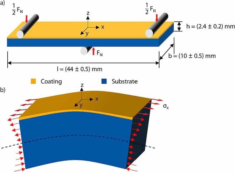
Fig. 2. a) Schematic of the 3-point bending test setup for cyclic bending tests at high stress amplitude along with b) stress distribution in x-direction on x-y plane and x-z plane of the sample during bending.
The cyclic bending tests with comparatively low stress amplitudes were carried out at Chair of Materials Test Engineering (WPT), TU Dortmund University, Germany, using a resonance testing system, Rumul Cracktronic, from Russenberger Prüfmaschinen AG, Neuhausen am Rheinfall, Switzerland. Fig. 3 schematically shows the test setup along with the sample geometry. In order to comprehensively study the fatigue behavior of the investigated variants at low stress amplitudes, load increase and single step cyclic bending tests were combined as per the recommendation in [14]. Initially, the approximate range of endurance limit for the uncoated and coated samples was determined using a step wise load increase test (LIT). As shown schematically in Fig. 4, the LIT for both variants was started with stress amplitude σa, start = 100 MPa, frequency f = 73 Hz and stress ratio R = 0.1. The stress amplitude was increased by ∆σa = 10 MPa after every ∆N = 10,000 cycles until sample fracture. The uncoated sample fractured at σa,f = 770 MPa, whereas the coated variant fractured at σa,f = 740 MPa. Based on that, the single step tests were carried out at stress amplitudes σa = 720 MPa, σa = 760 MPa, σa = 780 MPa, σa = 800 MPa and σa = 820 MPa with f = 73 Hz and R = 0.1. The stress amplitude σa in single step tests was kept constant until the sample failure or N = 1 × 10⁷ cycles, whichever occurred first.
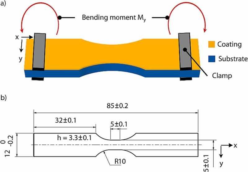
Fig. 3. a) Schematic of the test setup and b) sample dimensions in mm for cyclic bending tests at relatively low stress amplitudes.
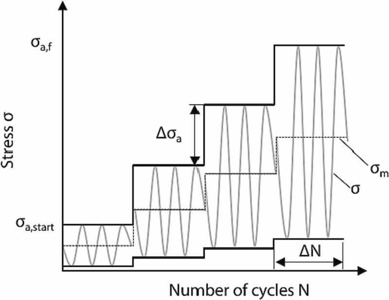
Fig. 4. Loading procedure of the load increase test (LIT).
2.3. Analysis of fatigue crack initiation
In order to find out, whether the surface or subsurface fatigue cracks initiate in the coating or substrate, the x-y plane along with coating-substrate interface in x-z plane of sample in Fig. 2 were identified as areas of interest for in situ SEM observation during cyclic 3-point bending test. For this purpose, the bending module, previously used for high stress amplitude tests, was installed inside a large chamber SEM, Mira 1430 VP, VisiTec, Ellcie Industries GmbH, Grevesmühlen, Germany. Preliminary test was carried out with the loading direction shown in Fig. 2a), whereby the coated surface, i.e. x-y plane, was in situ analyzed from the top. However, the propagation of fatigue cracks on the surface could not be captured in this case. The used combination of bending module and large chamber SEM only allowed the in situ analysis from the top. Therefore, in order to observe the crack sensitive interface between the coating and substrate in x-z plane during the test, the sample was loaded as shown in Fig. 5a). It is important to note here, that in situ monitoring test was carried out to analyze the fatigue crack initiation in the coated compound rather than the fatigue limit. Although the sample was loaded differently than the test setup in Fig. 2a), the interface area, relevant for in situ observation of fatigue cracks, still underwent a tensile stress in x-direction during bending. Moreover, the test setup in Fig. 5a) presented the advantage to subject the interface, coating and substrate area, being observed under the large chamber SEM, to a uniform stress in x-z plane during bending, see Fig. 5b). This offered the possibility to analyze, whether the fatigue cracks, under a uniform tensile stress on the observed interface area, initiate first in the coating or substrate. Therefore, the in situ monitoring test represented a model test focused on basic research of fatigue crack initiation in interface area of coated compound under tensile bending stress. These findings, regarding the initiation of fatigue cracks, can also contribute to understanding the surface or subsurface fatigue crack initiation in the coated samples loaded differently, as in Figs. 2a) and 3a. Considering the sample size limitations of the bending module, a smaller sample was prepared for the in situ monitoring test, see Fig. 5a). The loading procedure of the test is shown in Fig. 6. The test was started with an initial load of FN,start = 180 N, frequency f ≈ 0.05 Hz and loading ratio R ≈ 0.4. In order to reduce the experimental effort associated with in situ SEM monitoring, the bending load was increased to FN = 200 N after N = 1200 cycles and to FN = 240 N after N = 1300 cycles due to the absence of crack evidence in the observed region. Eventually the fatigue crack was first observed at N = 2000 cycles. The experiment was continued for ∆N = 500 cycles to further observe the damage propagation and finally stopped at N = 2500 cycles without sample fracture. Afterwards, the sample was taken out of the experimental setup and analyzed in detail with a high-resolution SEM, ZEISS DSM 982 Gemini, Carl Zeiss AG, Oberkochen, Germany. The in situ monitoring test and the subsequent damage analysis were carried out at GFE, RWTH Aachen University, Germany.
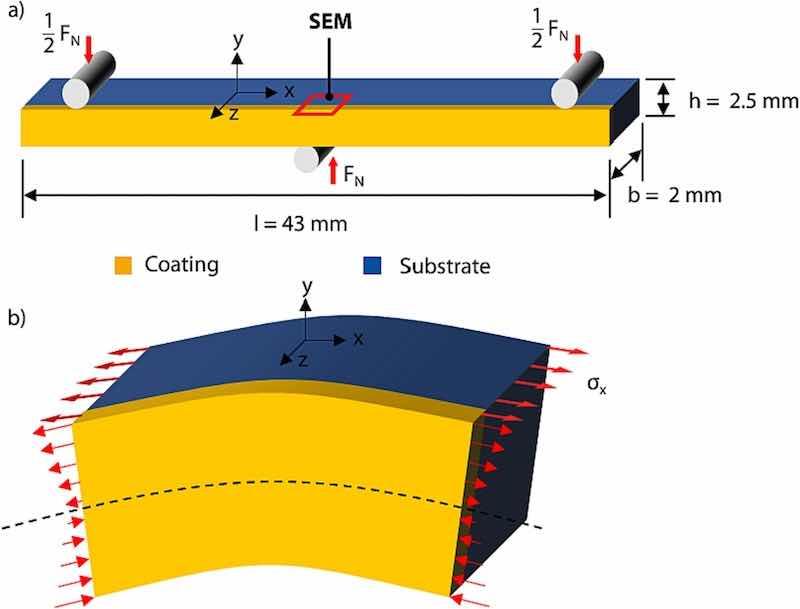
Fig. 5. a) Schematic of in situ monitoring test setup in large chamber SEM along with b) stress distribution in x-direction on x-y plane and x-z plane of the sample during bending.
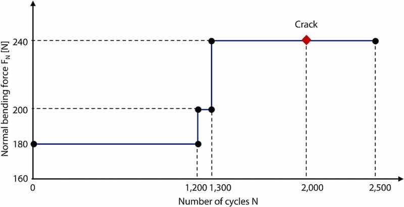
Fig. 6. Loading procedure of in situ monitoring cyclic bending test carried out in large chamber SEM.
3. Results
3.1. Coating properties
The coating properties such as thickness, chemical composition, thickness and indentation hardness HIT among others are summarized in Table 2. Moreover, the residual state of the coating confirmed the presence of compressive residual stresses in the range |σ| ~ 2.7–3.4 GPa [13].
Table 2. Coating properties and adhesion strength class of the investigated CrAlN/HS6–5-2C compound.
| Coating | CrAlN |
| Coating thickness s [μm] | 1.7 |
| Average line roughness Ra [μm] | 0.04 |
| Cr content [at. %] | 31 |
| Al content [at. %] | 16 |
| N content [at. %] | 53 |
| Indentation hardness HIT [GPa] | 26.7 ± 3.1 |
| Indentation modulus EIT [GPa] | 348 ± 36 |
| Adhesion strength class HF [−] | 3 |
3.2. Fatigue behavior
The results of 3-point cyclic bending tests, carried out as per Fig. 2, are shown in Table 3. All samples fractured between N = 274 and N = 654 cycles. However, no significant difference in number of cycles to failure Nf between coated and uncoated variants could be observed from the results. Overall, the tested samples showed a fatigue life of Nf = 471 ± 135 cycles under the used test parameters.
Table 3. Results of 3-point bending tests for uncoated and coated variants at high stress amplitude.
| Test # | Sample variant | No. of cycles to failure Nf |
| 1 | 537 | |
| 2 | Uncoated | 447 |
| 3 | 370 | |
| 4 | 274 | |
| 5 | Coated | 539 |
| 6 | 654 |
The damage analysis of the selected samples is shown in Fig. 7, Fig. 8. Fig. 7 exemplarily shows the surface of the fractured half sample from above. Compared to the uncoated variant, the coated samples showed longer cracks on the surface around the fracture area. The cracks visible on the uncoated HS6–5-2C surface are shorter in length and seem to be concentrated around the carbide phases. The cross-section images of the fractured uncoated substrate revealed several cracks running through or around the carbide particles, Fig. 8a) and b). In case of the coated variant, the fracture area did not exhibit any significant coating delamination or cracks running along the interface between coating and substrate. Fig. 8c) exemplarily shows that the coating remained mostly intact in the fracture area. Moreover, the surface or subsurface cracks ran through the coating, see Fig. 8d) and e). Hereby, two types of cracks were observed. The first type, as seen in Fig. 8d), were contained solely in the coating without any propagation into the substrate. The second type of cracks, as seen in Fig. 8e) and f), revealed a crack path including coating and substrate. At this stage, it remains unclear whether the crack initiated in the coating or substrate. However, in general, the cracks observed in the cross-section of coated samples were mostly concentrated around carbide phases in the substrate. Moreover, the bending tests at high stress amplitude revealed no significant effect of coating on the fatigue strength of the substrate.
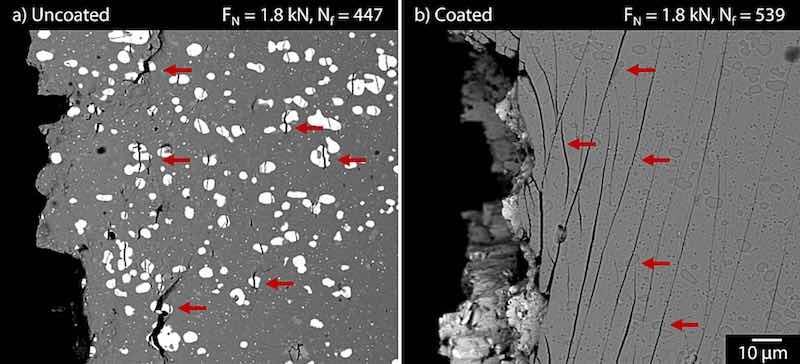
Fig. 7. SEM images of the surface around fracture area for (a) uncoated and (b) coated samples subjected to high stress amplitude 3-point bending test.
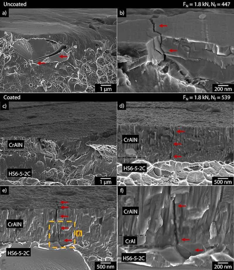
Fig. 8. SEM images of the fracture cross-section of (a-b) uncoated and (c-f) coated samples subjected to high stress amplitude 3-point bending test.
The results from cyclic bending tests at low stress amplitudes are shown in Fig. 9. With exception of one uncoated sample at σa = 760 MPa, which did not fail after N = 1 × 10⁷ cycles, the endurance limit for the tested uncoated samples could be below σa = 720 MPa. On the other hand, the coated samples seem to have a higher endurance limit, σa ≈ 760 MPa. The single step tests at σa ≥ 780 MPa were repeated to examine the effect of coating on fatigue behavior of coated samples above the endurance limit of coated samples. The single step tests for uncoated samples showed a good repeatability in number of cycles to failure Nf at σa ≥ 780 MPa. Interestingly, the coated samples showed a large deviation in fatigue behavior. Either the sample failed in a similar range as the uncoated variant or it exhibited a significant increase in the number of cycles to failure. This deviation in number of cycles to failure Nf for coated variants reduced as the stress amplitude increased from σa = 780 MPa to σa = 820 MPa. Hence, the fatigue behavior of the coated variants seems to be approaching that of uncoated substrate as stress amplitude increases. The damage analysis of the fracture surface of the samples showed small surface cracks for uncoated and large surface cracks for coated variant, as previously observed in Fig. 7. Moreover, no surface cracks were observed on the coated samples which did not fracture until N = 1 × 10⁷ cycles. Fig. 10 exemplarily shows the cross-section images of the fracture area for selected samples. Again, for uncoated variant, the cracks were mostly concentrated around the carbide particles, see Fig. 10a). As opposed to the coated samples tested at high stress amplitude, the observed coated variants subjected to low stress amplitudes did not reveal any cracks running through the coating cross-section. As shown in Fig. 10b), the coating remained mostly intact without any major cracks running through the coating. However, it is interesting to see a crack, marked by red arrow, running through the carbide particle in the substrate without further propagation into the coating. The fracture cross-sections of the coated variants showing a deviation in number of cycles to failure Nf at the same stress amplitude σa were also compared. The samples which withstood significantly larger number of cycles to failure showed locations with adhesive coating damage along the fracture area. Fig. 11a) and b) exemplary show the adhesive damage and cohesive plus adhesive damage, respectively, for the sample subjected to σa = 800 MPa. This sample showed a significant increase in number of cycles to failure, Nf = 1,549,683, compared to the uncoated samples as well the second coated sample. However, these locations with adhesive damage of the coating were absent for the second sample which failed at Nf = 33,591 cycles, see Fig. 10b).
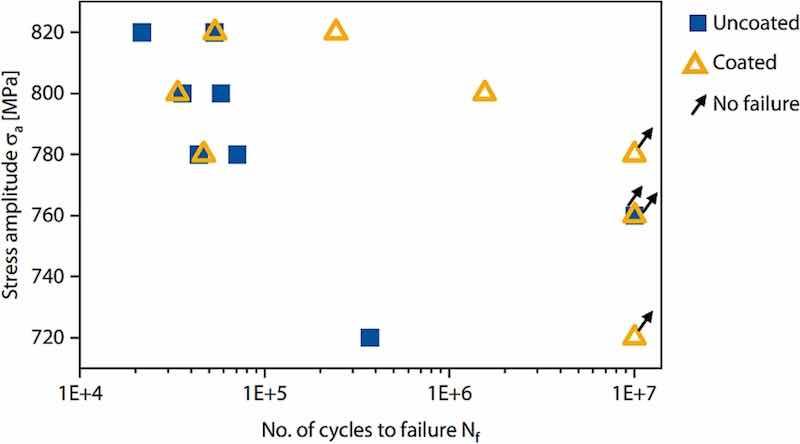
Fig. 9. Results of single step cyclic bending tests for uncoated and coated samples at low stress amplitudes.

Fig. 10. Fracture cross-section SEM images of (a) uncoated and (b) coated samples after single step cyclic bending test at σa = 800 MPa.
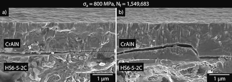
Fig. 11. SEM images of the a) adhesive and b) cohesive plus adhesive coating damage along the fracture cross section for the coated sample, which showed significant increase in fatigue life during single step cyclic bending test at σa = 800 MPa.
3.3. Fatigue damage mechanism
Fig. 12a), b) and c) show the in situ images from the test in large chamber SEM. The location on which the crack appeared is marked in Fig. 12a). The crack was first observed after N = 2000 cycles, see Fig. 12b). Eventually, the test was stopped after N = 2500 cycles to analyze the crack propagation in detail, see Fig. 12c). Fig. 12d), e) and f) show the high-resolution SEM images of the observed fatigue crack location. It can be seen that the crack path is concentrated around the carbide cluster in the substrate and the coating. However, it is unclear whether the crack initiated in the coating or substrate. As qualitatively confirmed by the EDX analysis, the carbide cluster showed peaks for carbide forming tungsten, molybdenum and vanadium, see Fig. 13. Moreover, the presence of small calcium peak also pointed towards the presence of nonmetallic inclusions in the carbide cluster. These large carbide particles or clusters and nonmetallic inclusions can act as fatigue crack initiation sites for high-speed tool steels [15,16]. In order to clarify whether the fatigue crack initiated in the coating or substrate, the area around the coating/substrate interface was analyzed along the sample length to identify other fatigue cracks. Several surface cracks were observed as marked by red arrows in Fig. 14a). Here the surface under investigation consists of coating, interface and substrate area, as schematically shown in Fig. 5. Fig. 14b) represents the EDX-map of Al to mark the coating. Fig. 14c-f) show the EDX-mappings based qualitative distribution of iron and carbide particles in the sample area from Fig. 14a). The large carbide particles and clusters are rich in tungsten, molybdenum and vanadium, see Fig. 14d-f). As reported in [17], W and Mo promote the formation of secondary M6C and MC carbides upon heat treatment. Another series of carbide particle apparent from the EDX-Mappings are V rich. As explained in [17], vanadium promotes the formation of separate MC-type carbide precipitates. The same is true for the present case. Such large W, Mo or V containing carbide clusters are typical for high speed tool steels after heat treatment. As apparent from Fig. 14a), other identified fatigue crack sites are also concentrated around the carbide clusters in the substrate. The crack paths at the locations marked in Fig. 14a) are shown in Fig. 15. The crack at location 1 in Fig. 14a), which went through the large carbide cluster can be seen in Fig. 15b). This crack did not reach the coating. The black elliptical shaped area in the crack path presumably represents nonmetallic inclusions or hole resulting from decohesion of these inclusions. This could also be a possible initiation site for this crack. The crack path at location 2 in Fig. 14a) included the carbide cluster and the coating, see Fig. 15a), c) and d). The crack width increased in the CrAl metallic interlayer. Eventually, the crack width reduced as it travelled inside the CrAlN top layer. The Fig. 15e-h) represent the crack path for location 3 in Fig. 14a). Fig. 15e) and f) represent the upper end of the crack in reference to the coating while Fig. 15g) and h) focus on the lower end. Again, the crack path, passing through the large carbide cluster and nonmetallic inclusion, remained in the substrate. It is interesting to note that the crack width increased as it travelled through the carbide particles and decreased upon entering the surrounding Fe-matrix. Fig. 16 shows two additional locations where fatigue cracks were observed inside the large carbide particles at the coating/substrate interface. In both cases, the surface fatigue cracks did not propagate into the coating. This again points towards the ability of the coating, having compressive residual stresses, to resist the substrate driven fatigue cracks to a certain extent. It is important to note that the damage analysis did not reveal any locations where the fatigue cracks were solely contained in the coating.

Fig. 12. In situ images from large chamber SEM (a) at the start, (b) after N = 2000 cycles and (c) after N = 2500 cycles of the test along with (d-f) high-resolution SEM images of the identified crack location.
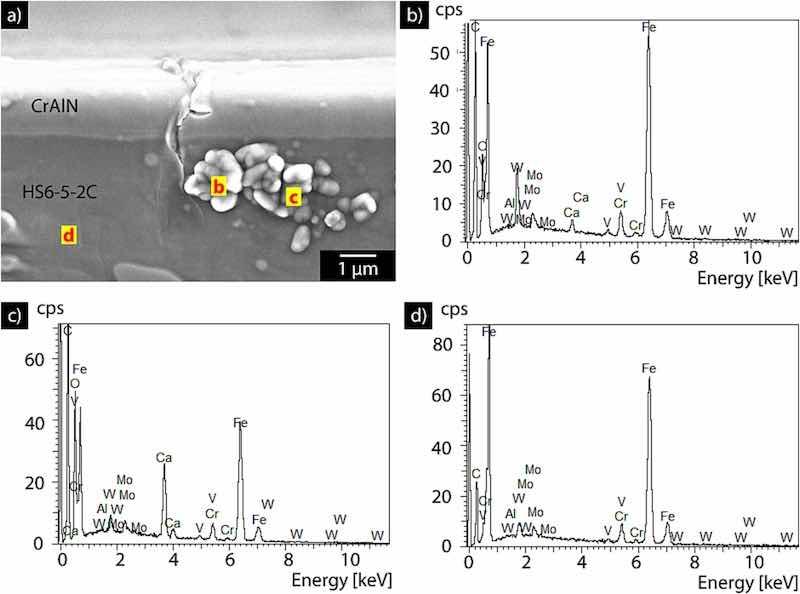
Fig. 13. a) Identified crack location during in situ monitoring test along with the qualitative EDX analysis of points b), c) and d).
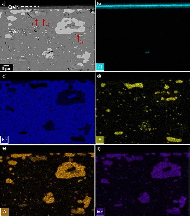
Fig. 14. (a) Crack locations marked with red arrows along with EDX-mapping of (b) Al, (c) Fe, (d) V, (e) W and (f) W of the area around fatigue crack locations for the sample subjected to in situ monitoring cyclic bending test.

Fig. 15. Crack paths for the fatigue cracks observed at location 1 (a-b), location 2 (c-d) and location 3 (e-h) in Fig. 14a.
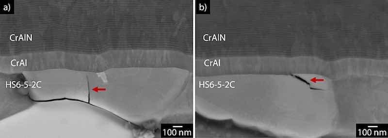
Fig. 16. Fatigue cracks observed on the interface between coating and substrate for the sample subjected to in situ monitoring cyclic bending test.
4. Discussion
Based on the observations in present study, the fatigue damage in PVD coated tool steel compound, whereby the coated surface and interface is subjected to tensile stress during bending, is largely initiated in substrate at low stress amplitudes. The large carbide particles, carbide clusters and nonmetallic inclusions at the surface or subsurface of substrate act as crack initiation sites. As mentioned in [15], the stress intensity factors around these carbide clusters and inclusions is high. Moreover, due to their high hardness and brittle deformation behavior compared to the surrounding Fe-matrix, these clusters may generate a notch effect to initiate fatigue cracks. For present case, the fatigue cracks mostly initiated on the interface or subsurface region of the substrate at low stress amplitudes. The PVD coating may resist the propagation of these fatigue cracks to a certain extent to improve the fatigue life of coated compound at low stress amplitudes, as apparent in Fig. 9. Here, the deformation behavior and residual stress state of the coating may play a significant role. In present case, the CrAlN coated tool steel samples showed an increase in endurance limit along with a significant deviation in fatigue behavior at low stress amplitudes above the endurance limit compared to the uncoated samples. Either the coated samples failed in a similar range as the uncoated variant or showed an increase in the fatigue strength.
This deviation in fatigue behavior has also been reported in [7] for TiN coated HS6–5-2 steel. It is hypothesized that two fatigue damage scenarios are simultaneously at play at low stress amplitudes. In first scenario, the substrate led fatigue cracks are suppressed by the coating due to the presence of residual compressive stresses. Resultantly, the fatigue strength of the coated sample increases. The sample eventually fails at a higher number of cycles, when the coating is unable to resist the substrate led fatigue damage because of the adhesive failure or increased crack network of the coating itself. In second scenario, due to the random distribution of fatigue crack initiating sites such as carbide clusters or nonmetallic inclusions at the substrate surface and subsurface, the substrate led fatigue damage may not always be suppressed or resisted by the coating. Moreover, the defects in coating may also lead to initiation of microcracks in the coating. These microcracks increase with every loading cycle and locally release the inherent compressive residual stresses of the coating. Hence, the coated sample fails in the similar range as of the uncoated substrate without any advantageous effect from the coating.
With the increase in bending stress amplitude, the ability of the coating to resist the substrate led fatigue damage decreases. As observed in present case, deviation in fatigue behavior of the coated samples decreased and started approaching that of uncoated samples as stress amplitude increased. Moreover, for a very high increase in stress amplitude, as was the case during 3-point bending tests, the coating had no significant effect on the fatigue behavior of the tool steel substrate. At high stress amplitudes, the coating and substrate undergo large deformation. Therefore, the fatigue damage mechanism moves from subsurface to surface at high stress amplitudes [7,18]. Here, the cracks may initiate from the defects at surface of the coating or substrate. Some of the coating cracks may further propagate into the substrate. Depending on the substrate, the fatigue behavior of the coated variant may deteriorate at high stress amplitudes [8] or remain unaffected as in present case.
5. Conclusion
Following are the main conclusions of the study:
- ▪The fatigue damage in PVD coated high speed tool steel compounds under cyclic bending load is largely initiated in the substrate at low stress amplitudes. Here, the large carbide particles, carbide clusters or nonmetallic inclusions at interface or substrate subsurface act as fatigue crack initiation sites.
- ▪Depending on bending stress amplitude, residual stress state and deformation behavior of the PVD coating, the coating may resist the propagation of fatigue cracks in certain cases to positively influence the fatigue behavior of tool steel substrate. The underlying fatigue damage scenarios at varying stress amplitudes are studied and explained in the study.
The investigation contributes to fundamental understanding of fatigue damage in PVD coated tool steel compounds. The subject of future work will be to investigate the effect of variation in coating properties such as residual stress state and elastic-plastic deformation behavior on fatigue behavior of the coated tool steel at low stress amplitudes.
Kirsten Bobzin, Christian Kalscheuer, and Muhammad Tayyab are with the Surface Engineering Institute at RWTH Aachen University, Germany.
Authorship contribution statement: K. Bobzin: Writing – review & editing, Supervision, Resources, Project administration, Funding acquisition, Conceptualization. C. Kalscheuer: Writing – review & editing, Supervision, Project administration, Funding acquisition, Conceptualization. M. Tayyab: Writing – original draft, Visualization, Methodology, Investigation, Formal analysis, Conceptualization.
Declaration of competing interest: The authors declare that they have no known competing financial interests or personal relationships that could have appeared to influence the work reported in this paper.
Acknowledgement: The authors gratefully acknowledge the financial support of the German Research Foundation, Deutsche Forschungsgemeinschaft (DFG), within the project BO1979/71-1. The authors would also like to thank A. Aretz and M. Spähn for in situ monitoring test in large chamber SEM and N. Baak for bending tests at low stress amplitudes.
References
[1] Y. Bai, J. Gao, T. Guo, K. Gao, A.A. Volinsky, X. Pang; Review of the fatigue behavior of hard coating-ductile substrate systems; Int. J. Miner. Metall. Mater., 28 (2021), pp. 46-55, 10.1007/s12613-020-2203-0
[2] J.F. Correa Jácome, J.C. Caicedo Angulo, Y.A. Castro; PVD coatings influence (TiCN, BCN, and CrAlN) on the fatigue life behavior of AISI 1045 steel for automotive applications; Int. J. Adv. Manuf. Technol., 119 (2022), pp. 3995-4009, 10.1007/s00170-021-08455-8
[3] P. Baldissera, S. Cavalleri, P. Marcassoli, F. Tordini, Study of the effect of DCT and PVD treatments on the fatigue behaviour of AISI 302 stainless steel, KEM 417-418 (2009) 49–52. doi:https://doi.org/10.4028/www.scientific.net/KEM.417-418.49.
[4] S. Baragetti, G.M. La Vecchia, A. Terranova; Variables affecting the fatigue resistance of PVD-coated components; Int. J. Fatigue, 27 (2005), pp. 1541-1550, 10.1016/j.ijfatigue.2005.06.011
[5] E. Puchi-Cabrera, F. Matı́nez, I. Herrera, J. Berrı́os, S. Dixit, D. Bhat; On the fatigue behavior of an AISI 316L stainless steel coated with a PVD TiN deposit; Surf. Coat. Technol., 182 (2004), pp. 276-286, 10.1016/j.surfcoat.2003.07.003
[6] D. Yonekura, A. Tsukuda, R.I. Murakami, K. Hanaguri; Fatigue properties of nitride Cr-Mo steel with CrN thin film deposited by Aip method; Int. J. Mod. Phys. B, 17 (2003), pp. 1554-1559, 10.1142/S0217979203019319
[7] H. Bomas, P. Mayr, B. Kurth; Fatigue properties of steel coated with TiN by a PVD process; Mater. Manuf. Process., 12 (1997), pp. 17-27, 10.1080/10426919708935116
[8] B. Zhang, A. Haghshenas, X. Zhang, J. Zhao, S. Shao, M.M. Khonsari, S. Guo, W.J. Meng; On the failure mechanisms of Cr-coated 316 stainless steel in bending fatigue tests; Int. J. Fatigue, 139 (2020), Article 105733, 10.1016/j.ijfatigue.2020.105733
[9] Z. Zhang, Y. Zhang, Z. Zhang, G. He; Effect of brittle TiN coating on fatigue performance of TC11 titanium alloy under rotating bending and tension-tension; J. Alloys Compd., 968 (2023), Article 172163, 10.1016/j.jallcom.2023.172163
[10] E.V. Arcieri, S. Baragetti; Fatigue Behavior of Thin Hard Coated Specimens Made of 7075, in: Fracture and Damage Mechanics: Theory; Mallorca, Spain, AIP Publishing, Simulation and Experiment (2020), p. 20027, 10.1063/5.0033959
[11] T. Guo, L. Qiao, X. Pang, A.A. Volinsky; Brittle film-induced cracking of ductile substrates; Acta Mater., 99 (2015), pp. 273-280, 10.1016/j.actamat.2015.07.059
[12] K. Bobzin, C. Kalscheuer, M. Carlet, M. Tayyab; Influence of aluminum content on the impact fatigue of HPPMS CrAlN coatings on tool steel; Phys. Mesomech., 24 (2021), pp. 625-632, 10.1134/S1029959921050143
[13] K. Bobzin, C. Kalscheuer, M. Tayyab; Effect of CrAIN coating properties on impact fatigue of tool steel; Surf. Coat. Technol. (2023), Article 129869, 10.1016/j.surfcoat.2023.129869
[14] F. Walther; Microstructure-oriented fatigue assessment of construction materials and joints using short-time load increase procedure; Materials Testing, 56 (2014), pp. 519-527, 10.3139/120.110592
[15] F. Meurling; Influence of carbide and inclusion contents on the fatigue properties of high speed steels and tool steels; Int. J. Fatigue, 23 (2001), pp. 215-224, 10.1016/S0142-1123(00)00087-6
[16] C. Sohar, A. Betzwarkotas, C. Gierl, B. Weiss, H. Danninger; Gigacycle fatigue behavior of a high chromium alloyed cold work tool steel; Int. J. Fatigue, 30 (2008), pp. 1137-1149, 10.1016/j.ijfatigue.2007.09.012
[17] E. Pippel, J. Woltersdorf, G. Pöckl, G. Lichtenegger; Microstructure and Nanochemistry of carbide precipitates in high-speed steel S 6-5-2-5; Mater. Charact., 43 (1999), pp. 41-55, 10.1016/S1044-5803(99)00003-0
[18] H. Mughrabi; Specific features and mechanisms of fatigue in the ultrahigh-cycle regime; Int. J. Fatigue, 28 (2006), pp. 1501-1508, 10.1016/j.ijfatigue.2005.05.018