In the market for eye-catching finishes, there is a persistent desire for a dark, high gloss look on both metal and plastic parts. The automotive fashion trend emphasizes subdued metallic palettes that provide a sense of depth and refinement.
Consumers are willing to pay a premium for styles that are visually and/or technologically unique, but many colors are marketed to match current fashionable or decorator color trends. In addition, blacks/smokes tend to be associated with performance brands and/or luxury that transcend the need for flashy, bright colors.
In many applications, the mechanical properties of plastic are sufficient, as the plastic is lighter and less costly to produce. However, applications such as automotive wheels require metals to withstand significant mechanical loads. Where possible, finishers prefer coating processes with the option to coat both plastic and metal substrates in the same system. In addition to color, durability is important to all applications. Decorative coatings that require high durability include automobile components, sanitary fixtures such as faucets, and durable goods such as home appliances. While multi-layer painted coatings are used for some of these applications, there can be issues with cost, durability, and the handling and recycling of volatile chemicals. Also, aggressive cleaning methods such as scrubbing with steel wool and strong cleaning chemicals used commonly for plumbing fixtures and car wheels are too aggressive for painted surfaces.
 When paints are insufficient for the look, performance, or durability, electroplating has been another common approach. Vendors of electroplating chemicals have developed proprietary systems to produce a range of dark coatings of different gloss levels. Many metals can be plated, but good plating of plastics is possible only on certain types of plastics. Plastic plating requires what are referred to as plating grade plastics, either acrylonitrile butadiene styrene (ABS) or polycarbonate/ABS blends. The electroplated substrate requires a butadiene etch to provide an anchoring texture. Several suppliers have invested significant capital for plating processes, but a deterrent to growth of electroplating, at least in the US and Europe, is the cost and risk of safely handling the required chemicals, often including hexavalent chromium. Hexavalent chromium is a known human carcinogen. This is not only required in some plating baths, but also to etch the ABS substrates.
Physical vapor deposited (PVD) coatings offer a pathway to produce colorful, hard, durable decorative coatings on many different substrates. Furthermore, PVD offers an acceptable capital outlay while completely avoiding the use of hazardous materials. However, PVD can be a hot process, and every substrate has temperature limits. Most metals have higher tolerance to heat compared to plastics. Since so many parts have been already qualified for electroplating, PVD needs to be capable of coating the common plating grade substrates. Plating grade plastics have a temperature limit in the range of 95°C to 130°C. Mixed substrates are not uncommon. It is common for plastic plumbing fixtures to begin with an electroplated surface to which a PVD decorative layer is applied. Conversely, metal automotive wheels often have an organic powder coat that receives the PVD coating. This article shows the approach to developing a coating on electroplated plastic used in plumbing fixtures, which could also apply without an electroplated coating or be used on metal substrates.
Product Definition and the Science of Characterization
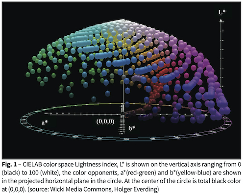
 Defining the exact appearance of a coating quantitatively can be a challenge. Color is scientifically defined by the CIE color space, CIELAB D65 is commonly used. An example of this color space is shown in Fig. 1.
CIELAB uses the L* lightness index to define pure black to pure white (0-100). The color opponents are defined as a* and b*. The component a* represents red as positive and green as negative numbers. The component b* represents yellow as positive and blue as negative numbers. By “dark”, a common color definition would be (L*, a*, b*) values near (40, 0, 0). Absolute black is at (0, 0, 0). A term called Chromaticity, C* is defined as: C*= (a*2 + b*2)0.5 . This is useful measure of the quality of color, independent of luminance. While gloss value (luster or shine) should be specified for the product [1], a hard PVD coating is likely to be highly specular and relatively thin compared to the substrate texture. Coating gloss will be determined by the characteristics of the substrate.
Also, the defined coating appearance has to be durable. The coating must adhere well and appear unchanged after exposure to ultraviolet light, immersion in harsh cleaners, immersion in corrosive chemicals, thermal shock, and abrasion. The selection of an abrasion or wear test is very application specific, and there over 100 such documented tests [2]. All such tests consist of some imposed loading followed by an assessment of damage. Based on conversations with plumbing fixture manufacturers, abrasion resistance was assessed by cycling steel wool soap pads, e.g. Brillo or Ako pads, 1000 strokes under 20 N/cm2 (29 psi) load and visually assessing damage.
 With a range of possible colors, cathodic arc ZrCN PVD transition metal nitrides and carbonitrides have been used as durable decorative coatings on metals for years in industrial applications. Zirconium is an attractive transition metal due to its outstanding chemical and physical properties. Research has shown that ZrN has high thermal [3] and chemical stability [4], as well as high hardness [5] and low electrical resistivity [6]. ZrN films have been used for decorative purposes due to their golden color [5], as well as other colors [7]. Carbonitrides can be dark rather than gold. ZrCN films have demonstrated high hardness [25], high chemical and thermal stability [8], good tribological and corrosion behavior [5], and are therefore good candidates for effective protective coatings against wear, abrasion and corrosion [9].
ZrCN coatings have been prepared by different techniques including plasma assisted CVD [10], arc evaporation [11,12], magnetron sputtering [15] and ion beam sputtering [16]. Literature concerning ZrCN films deals with the process details of plasma-aided chemical vapor deposition, mainly discussing how to grow ZrCN films at relatively low temperature [10,13]. Hollstein et al. [11] deposited a group of ZrCN films by means of cathodic arc and investigated their use for tools used in minimally invasive surgery. The result indicated that ZrCN is a candidate for coatings on surgical tools where short-term biocompatibility is required. Rie et al. [14] deposited a group of Zr-based films and found good corrosion resistance with ZrCN films. Yao et al. [15] showed that over an acetylene-nitrogen (C2H2:N2) ratio of 4 to 2, the hardness and wear behavior of ZrCN films depended strongly on the ratio, with highest hardness and least wear at the lowest ratio of 2 for C2H2:N2 reactive gas flow rates. Using a flow of methane (CH4) ion beam sputtering revealed a maximum in hardness of of ZrN1-xCx at x= 0.6, corresponding well to a theoretical model [16].
 Direct current reactive magnetron sputtering offers a few potential advantages over a cathodic arc approach to ZrCN on plastic parts. Many molded parts have complex, high aspect ratio geometry. To achieve uniform coating on the visible areas, it is necessary to move parts through many angles and positions. This is usually done with either a single axis or planetary rotation arrangement. The plastic is also electrically insulating, unless electroplated. Cathodic arc coatings typically rely on an electrical bias for density and hardness. The motion and insulating nature of substrates can make applying a bias challenging in a production environment. A sputtered coating may not need bias. A sputtered film is also likely to be smoother, without the macro particles common to cathodic arc. Even if the properties of the sputtered film were on par with cathodic arc film, the large installed base of sputter tools would benefit from adding such a coating to their repertoire.
The bounds on film thickness are set by heat tolerance of the substrate and absorptivity of the coating. Substrate heating mechanisms for sputtered films have been well documented [17,18]. The need to stop deposition before the substrate is softened sets an upper limit. Although a large gamut of colors is possible if interference effects are employed [19], a uniform color from PVD on parts of arbitrary 3D shapes can be challenging unless the coating is completely opaque. Otherwise, minor variations in film thickness produce undesired rainbow color effects. One way to obtain uniformity is to use a combination of thickness and absorptance that keeps the amount of reflection from the coating-substrate interface that arrives at the air-coating interface less than a few percent of the reflection from the air-coating interface. This product of absorption coefficient and thickness sets a lower limit on thickness.
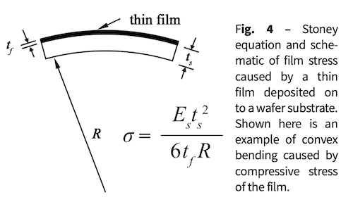
Film stress influences both adhesion and abrasion resistance of these films. High tensile film stress can make the coating very sensitive to opening up visible cracks in response to scratches, while some compressive stress can help scratches from opening cracks through the coating. However, too much compressive stress can cause the coating to buckle away from the substrate. The development challenge is to find a single set of conditions that simultaneously satisfy all the conditions of appearance, durability and temperature.
Developing the ZrN Deposition Process
 Development began with locating a suitable ZrN coating process using a dc power supply and having the deposition chamber as an anode. Gases were introduced through stainless steel tubing with occasional small holes. Maintaining a 50/50 mix of Ar and N , an N flow was found where the target was fully poisoned. This produced the well-known gold color. From there, acetylene (C2H2) was added. It was found that resulting film was not only very hard, but also very electrically insulating, creating a strong disappearing anode effect. The only part of the chamber that remained electrically conductive was a few mm around the gas feed holes of the manifold. Since all the current was focused there, the manifold melted. This was overcome with a water-cooled discrete anode and an Advanced Energy AMS/DMS operated in what has been referred to as “Pelleymode”[20], although with only a single cathode.
We also discovered a significant impact of gas flow within the system for the incorporation of carbon into the sputtered films. The magnetron is positioned approximately 2 feet (61 cm) from the diffusion pump plenum. One gas manifold was placed near the pump plenum, while another was placed about 6 inches (~15 cm) to the other side of the magnetron, away from the plenum and close to the magnetron.
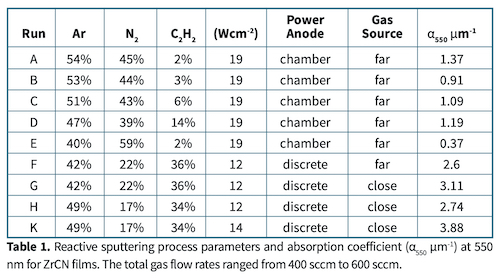
A series of coatings was produced with total gas flow between 400 sccm and 600 sccm. Relative flow rates of the three process gases are shown in Table 1.
Determination of Film Optical Properties
 Although many approaches to determining the absorption coefficients of thin films have been addressed over the decades [21] using spectrophotometers or ellipsometers, a rapid and inexpensive method was sufficient to guide process refinements. Films with thickness, d, thin enough to allow low transmission across the visible spectrum were deposited onto glass slides. Transmission and film-side reflection were measured with an Ocean Optics USB2000 fiber optic spectrometer. Since these films were so specular (non-scattering) all the measured light is accounted for. The sum of transmittance, T, reflectance, R, and absorptance, A, is (T(λ) +R(λ) +A(λ) =1). Under these conditions the absorption coefficient, α(λ), and thickness, d, and where A0(λ) and Ai(λ) are the initial and final light levels measured, is expressed by:

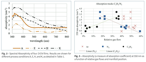
We found we could ignore errors in derivation of α from sources such as back side reflection and mis-registration between T and R measurement locations for the purpose of selecting process parameters. Optical thin film modeling would have required more accurate, traditional methods. Because of this approximate method we will refer to this approximate absorption coefficient as absorptivity. Fig. 2 shows the spectra of four different films. The lower plots are from films with 15% or less of C2H2, while the upper plots are from films with 33% or more C2H2. The low C2H2 films had a gold appearance, although the color was not as saturated as ZrN films. The change in shape of the plots indicates a fundamental change in the material band structure. Table 1 shows the values for each coating at 550 nm. The large increase in absorptivity between conditions F and G indicate how much more carbon was incorporated with a gas manifold close to the magnetron, away from the pump plenum. Fig. 3 shows that, while absorptivity does not depend exclusively on C2H2, the dependence is strong and nearly linear.
Determination of Film Stress
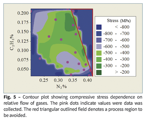
 A subsequent series of coatings that were thick enough to be opaque were produced on both plastic and silicon wafer substrates. Many of these films displayed high compressive stress; some films spontaneously delaminated. Stress was measured using pre-characterized silicon (100) wafers, a profilometer to measure curvature, and Stoney’s equation [22] for a single film on a substrate, where s is the film stress, Es is Young’s modulus of the substrate, R is the radius of curvature of the wafer, ts and tf are substrate and film thickness, respectively. Fig. 5 shows stresses measured on silicon wafers as compressive as -800 MPa. However, on the plastic substrates, the film stress is likely to be much more compressive.
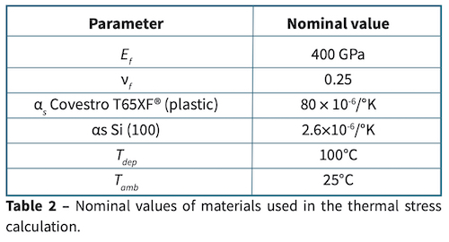
The stress due to thermal contraction can be estimated as follows. The coating is deposited hot, and the entire system contracts as it cools to room temperature. The film is much thinner than either of the substrates, so the substrates contract, applying a stress to the film. The total stress on the film is comprised of the thermal stress, the intrinsic film stress, and any externally applied forces.
![]()
 Assuming the mechanical properties are isotropic in the plane of the coating, and that the coefficients of thermal expansion of film and substrate, αf and αs, do not vary much over the temperature range,
If external forces are negligible or identical for both the wafer and plastic,

The total stress on the wafer is what is measured with the profilometer. When these are subtracted we get,
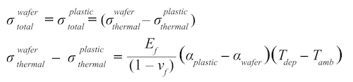
The film coefficient, αf disappears from the relationship. Using values gleaned from literature, compiled in Table 2 the film on a plastic substrate may be -3.1 GPa more compressive than the value measured from the silicon wafer. This analysis may overestimate the thermal effect, since it assumes the system was at thermal equilibrium before any coating was applied, and that the different substrates absorb heat equally. However, it shows that the thermal effect cannot be ignored.
Determination of Film Abrasion Resistance
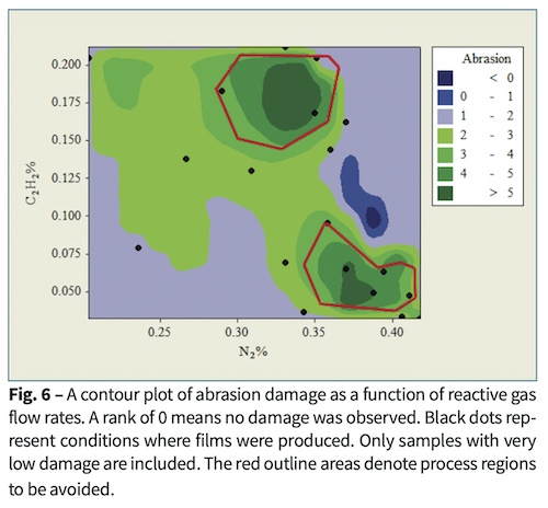
Abrasion was assessed as the percentage of area where coating was removed. Films made with very high C2H2 flows were easily damaged. Films that required microscopic observation to assess steel wool abrasion were assessed between 0% and 2% removal. Among these, Fig. 6 shows that flows near 10% C2H2and 38% N2 survived without damage.
Determination of Film Chromaticity
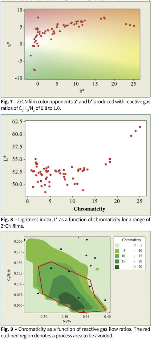
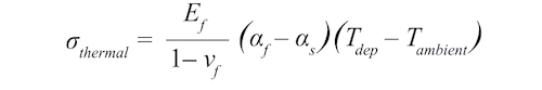
 Although the opaque ZrCN films displayed a wide range of colors, those colors followed a pattern. We use chromaticity as a color measure to show the quality of color. Fig. 7 shows that films followed a characteristic track for coatings produced with reactive gas ratios C2H2/N2 between 0.08 and 1. Fig. 8 shows that the films with lower chromaticity were darker. Fig. 9 shows that low chromaticity was achieved at higher values of both reactive gases.
Conclusions
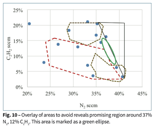
Excellent fundamental work on designed experiments to optimize process conditions in multivariable response surfaces has been available for years. Also, more mathematically oriented approaches exist in the literature. They essentially rely on devising weighting functions for the various responses [23]. Designed experiment methods are excellent when a rudimentary process is already established. Here, no such process existed. However, rather than a purely empirical approach, a method of overlaid contour plots is roughly followed [24]. This is good for three variables. The need was to identify the main variables and determine boundaries for a best possible operating space.
The competing demands of good abrasion resistance, moderate stress for good adhesion, and dark, neutral color are almost mutually exclusive. By overlaying plots of chromaticity, absorptivity, film stress and damage with respect to process gas flow rates, acetylene and nitrogen, a composite plot in Fig. 10 was made to show potentially the process conditions to make a film with the best characteristics. Direct current reactive magnetron sputtering with a discrete anode produced moderately dark, neutral ZrCN coatings on plastic parts in a very narrow process space. More generally, a method was shown how to approach a new coating that has multiple, and sometimes conflicting requirements.
In the future, we will develop methods of creating greater incorporation of carbon to make a darker coating without overheating the plastic substrate or losing abrasion resistance. This may include addition of a.c. or r.f. electrodes with the sputtering process. The sputtering process space for both hard and dark films may be widened by operating at less than fully poisoned conditions using emission spectrometry control. This could change the relative arrival rate ratio of metal/non-metal which shows a way to increase film hardness [25].
Acknowledgments
Many thanks to Gary Vergason, Mark Fitch and Rick Smith, Verguson Technology for their continued support.
About the Author: Michael Brazil
 Michael Brazil is the senior scientist at Vergason Technology, Inc. A process engineer at heart, Michael has been developing vacuum deposited thin films and the tools to manufacture them since the early 1980’s for a wide variety of industries in the US and China, including automotive windshields and trim, architectural glass, recording media, lithographic printing, flexible circuits, EMI shielding, photovoltaics, consumer electronics and telecommunications. He patented the XIR windshield coating, now owned by Eastman and in more than 20 million cars. He has worked for large, well-known companies like Guardian Industries, Seagate and Corning, as well as small companies like Southwall and Presstek. He graduated from Pomona College with a B.A. in physics and from the University of California at Berkeley with a Ph.D. in materials science.
References
1. G.Kigle-BöcklerandH.K.HammondIII,“Gloss”,Chap.44inPaintand Coating Testing Manual, 15th edition, J. V. Koleske, edit, ASTM, West Conshohocken, PA, 2012
2. Selection and Use of Wear Tests for Coatings, ASTM Special Technical Publication 769, R.G. Bayer, edit, 1981; D.K. Slawson, “Abrasion Resistance,” Chap. 45 in Paint and Coating Testing Manual, 15th edit., J. V. Koleske, ed, ASTM, West Conshohocken, PA, 2012.
3. D. Wu, Z. Zhang, W. Fu, X. Fan, H. Guo, “Structure, electrical and chemical properties of zirconium nitride films deposited by dc reactive magnetron sputtering,” Appl. Phys. A 64, pp. 593-595, 1997. http://dx.doi.org/10.1007/s003390050522.
4. E.Kelesoglu,C.Mitterer,M.K.Kazmanli,M.Urgen,“Corrosioncharacteristics of plain carbon steel coated with TiN and ZrN under highflux ion bombardment,” Surf. Coat. Technol., 116, pp. 82-86, 2002. http://dx.doi.org/10.1016/S0257-8972(02)00358-4
5. R. Constantin, B. Miremad, “Performance of hard coatings, made by balanced and unbalanced magnetron sputtering, for decorative applications,” Surf. Coat. Technol., 120-121, pp. 728-733, 1999. http:// dx.doi.org/10.1016/S0257-8972(99)00366-7
6. C.C.Wang,S.A.Akbar,W.Chen,V.D.Patton,“Electricalpropertiesof high-temperature oxides, borides, carbides, and nitrides,”J. Mater. Sci., 30, pp. 1627-1641, 1995. http://dx.doi.org/10.1007/BF00351591
7. M.H. Bouix and C.P. Dumortier, “Color trends in PVD,” 43rd Annual Technical Conference Proceedings of the Society of Vacuum Coaters, pp. 52-54, 2000.
8. W. Fleischer, T. Trinh and P. Willich, “Surface oxidation of decorative hard coatings with enriched carbon content,” 43rd Annual Technical Conference Proceedings of the Society of Vacuum Coaters, pp. 46-51, 2000.
9. M. Braica, V. Braica, M. Balaceanua, C.N. Zoitaa, A. Kissa, A. Vladescua, A. Popescub, R. Ripeanub, “Structure and properties of Zr/ ZrCN coatings deposited by cathodic arc method,” Materials Chemistry and Physics 126, pp. 818–825, 2011. http://dx.doi.org/10.1016/j. matchemphys.2010.12.036
10. L. Alberts, D. Boscarino, A. Patelli, V. Rigato, H. Ahn, and K.T. Rie, “Ion beam analysis of low-temperature MO-PACVD coatings,” Surf. Coat. Tech., 169-170, pp. 388-392, 2003. http://dx.doi.org/10.1016/S02578972(03)00062-8
11. F. Hollstein, D. Kitta, P. Louda, F. Pacal, J. Meinhardt, “Investigation of low-reflective ZrCN PVD-arc coatings for application on medical tools for minimally invasive surgery,” Surf. Coat. Technol. 142–144, pp. 1063, 2001. http://dx.doi.org/10.1016/S02578972(01)01222-1
12. J.-D. Gu, P.-J. Chen, “Investigation of the corrosion resistance of ZrCN hard coatings fabricated by advanced controlled arc plasma deposition,” Surf. Coat. Technol. 200, pp. 3341-3346, 2006. http://dx.doi. org/10.1016/j.surfcoat.2005.07.049
13. J. Wöhle, C. Pfohl, K.-T. Rie, A. Gebauer-Teichmann, S.K. Kim, “Deposition of TiCN and ZrCN layers on light metals by PACVD method using radio frequency and pulsed-DC plasma,” Surf. Coat. Technol. 131, pp. 127-130, 2000. http://dx.doi.org/10.1016/S02578972(00)00749-0
14. K.-T. Rie, A. Gebauer, J. Wöhle, “Plasma assisted CVD for low temperature coatings and corrosion resistance,” Surf. Coat. Technol. 86-87, pp. 498-506, 1996. http://dx.doi.org/10.1016/S02578972(96)03177-5.
15. S.H. Yao, Y.L. Su, W.H. Kao, K.W. Cheng, “Wear behavior of DC unbalanced magnetron sputter deposited ZrCN films,” Materials Letters 59, pp. 3230 – 3233, 2005. http://dx.doi.org/10.1016/j.matlet.2005.04.064
16. M.M. Larijani, M.B. Zanjanbarb, A. Majdabadia, “The effect of carbon fraction in Zr(C, N) films on the nano-structural properties and hardness,” J. Alloys and Compounds, 492, pp. 735–738, 2010. http://dx.doi.org/10.1016/j.jallcom.2009.12.035
17. R.P. Howson. and H.A. J’Afer, “Substrate effects from an unbalanced magnetron,” Thin Solid Films 193-194, p. 127-137, 1990. http://dx.doi. org/10.1016/S0040-6090(05)80020-3
18. W.D. Westwood, Sputter Deposition, American Vacuum Society, pp. 64-66., 2003.
19. M. Eerden, M. Schreurs, P. Schreurs, and R. Tieterna, “Oxygen as a Reactive Gas: Opportunities in the Decorative Coating Field,” 47th Annual Technical Conference Proceedings of the Society of Vacuum Coaters Coaters, pp. 556-559, 2004.
20. D. R. Pelleymounter, “Raising the bar on reactive deposition sputter rates,” 58th Annual Technical Conference Proceedings of the Society of Vacuum Coaters, pp. 1-5, 2015.
21. Computer software, e.g., “The Essential Macleod,” Thin Film Center, Tucson, Arizona; “OptiChar,” www.optilayer.com.
22. G.C.A.M. Janssen, M.M. Abdalla, F. van Keulen, B.R. Pajuda, and B. van Venrooy, “Celebrating the 100th anniversary of the Stoney equation for film stress: Developments from polycrystalline steel strips to single crystal silicon wafers,” Thin Solid Films, 517, pp. 1858-1867, 2009. http://dx.doi.org/10.1016/j.tsf.2008.07.014
23. G. Derringer, and R. Suich, “Simultaneous Optimization of Several Response Variables,” Journal of Quality Technology, 12(4), pp. 214219, 1980.
24. D.C. Montgomery, Design and Analysis of Experiments, 7th ed., Wiley & Sons, p. 435 ff., 2009.
25. M. Braic, M. Balaceanu, A. Vladescu, C.N. Zoita, V. Braic, “Study of (Zr,Ti)CN, (Zr,Hf)CN and (Xr,Nb)CN films prepared by reactive magnetron sputtering,” Thin Solid Films 519, pp. 4092-4096, 2011. http://dx.doi.org/10.1016/j.tsf.2011.01.375