Pollution restrictions are a major focus in today’s finishing industry. Unlike the year 1929, when Reliable Plating Works (RPW) was founded, today’s business has to answer to the EPA.
 Jaime MaliszewskiEven in 1967 and 1972, when RPW installed its first two fully automated plating lines, there was little concern as to how all the increased waste would be disposed of. The system most shops used was dilution. Unfortunately, the only solution to pollution is no longer dilution.
In this paper, Reliable Plating Works would like to share with you their award-winning process, which earned them Wisconsin’s Governor’s Award for Hazardous Waste Treatment. This award was given to RPW for its ability to surpass Wisconsin’s strict pollution regulations while at the same time increasing its efficiency and profitability.
Editor's note: this paper was written in the 1990s, but its principles hold true today. Costs and numbers have not been changed, but must be accounted for as higher costs of today.
RPW had to face this challenge many years when they were installing a new manufacturing plant that would house Wisconsin’s largest fully automated job shop, a plating line for decorative nickel and chrome. This hoist line stretched 120 feet DOT by 1.8 feet in height and 12 feet in width. The hoist would have the capability to plate 1,000 square feet of plating per hour. In other words, not only would this hoist generate a large volume of finished goods, but it would also generate an enormous amount of waste to be treated. Treatment of this waste began by treating it the cleaner solutions.
Extending the Life of Cleaners
The late John Maliszewski, then President of RPW, should be credited with selecting the system that not only helped RPW meet full compliance but also tripled the life of the cleaners.
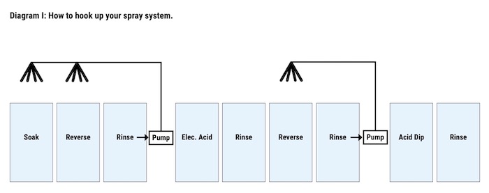
The system he chose began with a series of sprays and counterflows installed in its cleaning cycle. John knew that the easiest way to extend cleaner life would be to increase rinsing above the cleaner tanks, not allowing the wetters and caustics to drag out of the solution. By using rinse water to spray the parts as they exited the cleaner tanks, RPW was not only able to decrease the amount of material dragged out of the solution; they were able to pump some of the material back into the cleaner tanks from the rinse tanks. (See Diagram I)
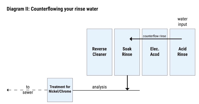
The caustic that is left in the rinse water is then used to lower the pH of the acid rinse’ water. RPW was able to do this with the help of counterflows. These counterflows traveled from the acid rinse tank into the caustic rinse tank and finally into a limestone holding tank which leads into the sewer. The flow into the Limestone holding tank should be monitored in order to ensure acceptable pH levels (See Diagram II).
With the addition of sprays, RPW avoided increased dwell times, longer, more costly cycle times, higher material costs, and greater chances of plating problems such as dry-on.
The sprays that were used accounted for about 75% of the total life extension of the cleaners. The last 25% was attained when Jack Maliszewski, C.E.F., Exec. VP started a de-sludging and skimming program. This program began by mixing the caustic rinses with the acid rinses” to achieve proper pH so that the rinse water could be let down the sewer. Once these tanks are emptied, the cleaner solutions can be pumped into one of the empty rinse tanks for storage while employees remove the sludge that is left at the bottom of the cleaner tanks. This sludge is then placed in one of three large holding tanks until it is hauled off sight when the storage tank becomes full. The sludge-free cleaners are then returned to their appropriate tank, and the rinse tanks are filled with fresh water. This process is done after the cleaner has run for three months and allows it to run another three months before it has to be moved into one of the storage tanks and made up new.
The second part of this program, skimming, is done once every week and takes about 15 minutes per tank on a Saturday. In this process, the cleaner tank must first be cooled and left to settle overnight so that the oils and grease are allowed to separate from the solution and float to the top, where an employee is able to skim it off into an overflow trough. The trough is then pumped directly into one of the holding tanks.
The acid baths, however, were not sprayed, skimmed, or de-sludged. In order to increase the life of the Acid bathes, RPW decided to use filtration and bath rotation. The filtration is done by carbon filters that are attached to both the electrified acid bath and the acid dip bath. The filters remove all the grease from the solution. Bath life was further increased by rotating the acid dip bath into the spent electrified acid tank. By doing this, the cost of making this bath up from scratch is saved. The acid dip bath still has to be made up new. Through filtration and bath rotation, acid baths are able to last for one month in each tank. This extended the bath life at RPW from two weeks to two months.
Not only did RPW save money on the cost of material, but they were also able to decrease the grease-related rejects by 90%. The only cost — other than the cost of hooking up the filters — was the cost of one manhour every week that is used to clean the filter and change the cartridges. The cost savings of all the above-mentioned recovery systems are noted in the summary.
Evaporating to Recover Your Nickel Solutions
During these days of skyrocketing nickel prices, no one wants to see nickel solution, which contains precious nickel metal, being hauled away as waste. It would be a much better sight to see one of your workers pumping the saturated nickel solution back into your nickel tanks that have been concentrated by evaporating the water out of the solution.
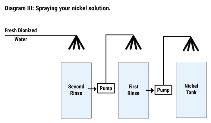
The first step to recovering the nickel solution is to install sprays above the nickel tanks. These sprays will spray the parts as they exit the nickel tank, using water from the first rinse after the nickel. The first rinse after the nickel is then sprayed with water from the second rinse after the nickel (See Diagram III). By spraying these tanks back into the nickel, the solution which is dragged out of the nickel tank will be sprayed back into the nickel tank through the sprays. Although these sprays reclaim some of the nickel solutions, there was still a need to reclaim more of the dragged-out nickel solution in order to reach 100% recovery.
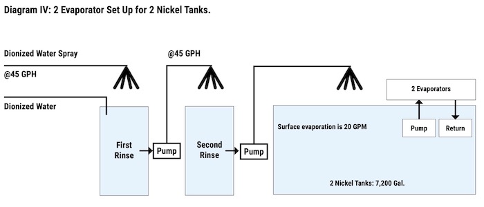
Since the flow of solution was flowing back into the nickel tank in order to reclaim the dragout, it was necessary to make room in the nickel tank so that the reclaimed solution would have a place to go. Two atmospheric evaporates were attached to the system, one per 3,600-gallon nickel tank, in order to make room for the recovered solution. The evaporators were able to work at a rate of 100 gallons per hour with the help of surface evaporation from the two 145°F nickel tanks. At this rate, they were able to empty the first nickel rinse once every 22 hours by pumping the solution from the first rinse back into the nickel tanks.
To ensure that no nickel would escape down the line, a counterflow was added, which moved the water from the second rinse into the first rinse tank. Reliable Plating was able to recover all of its nickel solutions (this includes brighteners, nickel salts, nickel chloride, etc.) that were dragged out of the nickel tank and return them to the nickel tank by using sprays, evaporators, counterflows, and pumps (See Diagram IV).
Although RPW was able to hold its nickel discharge in compliance, other areas, such as zinc, lead, and calcium, began to climb, causing plating problems. It seems that the evaporators were making too much recovery. Even though RPW had no zinc house, zinc levels were rising. The source was found to be the city water, which after recovery, increased in impurity levels. The solution to this problem was the installation of a deionize water unit. This unit eliminated the impurity problems not only in the recovery of the nickel solution but also in the recovery of chromium. Deionized water is used to fill all tanks leading into the recovery tanks to avoid this build-up of impurities.
How to Recover Low-Temperature Chromium
Evaporating your chromium solution may sound difficult to do since the temperature of the bath is generally about 112°F. At RPW, it was found that only 12 gallons of solution could be evaporated per hour by the use of an atmospheric evaporator and surface evaporation from the chromium tank. This evaporation rate was unable to make up for the solution that was being dragged out and counterflowed back into the chromium tank. There was still a need to increase the evaporation of the solution so that more rinse water could be counter flowed back into the chromium tank.
To increase the evaporation rate, RPW had to change its drag-out tank into a Recovery tank. This change was done by running a heating coil into the new recovery tank that would heat the solution to 140°F (a suitable temperature for evaporation). This solution was then pumped through a second evaporator which increased total evaporation from both tanks (evaporation includes both tank’s surface evaporation and evaporation from the evaporators) to 45 gallons per hour.
By evaporating the chromium solution, a chromium mist is produced that must be piped into your fume scrubber. This must be done so that in gaining your wastewater compliance, you don’t go out of compliance by polluting your air. By doing this, you are also able to reclaim the chromium that is pulled out of the air by your fume scrubber and put it back into your chromium tank.
Counterflows were also used to move the dragged chromium solution back through their rinse tanks and back into their chromium tank. This left no rinse water going into the sewer.
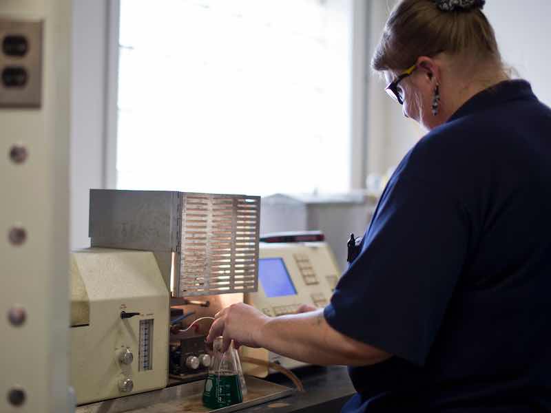 A Reliable Plating Works staff members tests the wastewater system at the plant.In order to complete the system, RPW had to add a series of sprays to all the chromium rinses, the recovery tank, and the chromium tank. The sprays not only doubled the amount of rinsing on the parts, but they also helped the flow of concentrated solution back into the chromium tank. By doing this, you are able to add fresh deionized water to the last rinse keeping it cleaner, which causes your parts to come out with only minor water spotting.
By solving our waste problems, we increase the impurity levels in our chrome. To eliminate this, we added a Clay Pot Reverse Osmosis System that pulled out our unwanted chlorides, trivalent chromium, and other metals. This system works so well that we added one to all of our lines in less than six months. The sludge from this system can be dried and sold to metal smelters such as nickel and chromium.
As you all know, Murphy’s Law states that if it can happen, it will happen, and so RPW added its safety catch. The safety catch consists of a Rapid Sand Pressure Filtration System, Activated Carbon Cartridge Filtration, and a Metal Selective Ion Exchange Unit. This system was installed just so RPW could get past burps in the system (parts with no drain holes, etc.).
The Rapid Sand Pressure Filtration System protects the Ion Exchange Unit from iron oxide fouling. This system will collect dirt and iron oxide and will not affect the downstream concentration of regulated metals (nickel and chromium). A standby filter is needed for times when backwashing is needed on the primary filter. This secondary filter will now run until it requires a backwash. All backwash material from these filters is clear for direct sewer discharge.
The Activated Carbon Cartridge Filtration System, which follows the Rapid Sand unit, protects the Ion Exchange unit from oil and grease fouling of the resin. This is necessary even though our waste stream consists of only 5 mg/l of oil. The carbon cartridges are replaced weekly (or as needed) and do not generate any hazardous waste for treatment.
The Metal Selective Ion Exchange Unit, which is the final step in our treatment system, will remove the regulated soluble metals through the utilization of selective ion exchange. Selective ion exchange will be accomplished by employing a chelating cation exchange resin in the sodium form that is preferential for heavy metal cations in the following order of selectivity as compared to calcium: mercury 2800:1, copper 2300:1, lead 1.200:1., nickel 57:1, tri-chrome 20:1., zinc 17:1, cadmium 15:1, cobalt 6.7:1, iron (ferrous) 4:1, manganese 1.2:1, and calcium 1:1. In order to recover hexavalent chromium (which acts as an anion) the cationic chelating resin will be capped with an anionic resin operating in the hydroxide form.
We use two 100% capacity ion exchange columns that are charged with three cubic feet of resin each. These units will run for approximately three weeks before they will have to be recharged. When recharged, the resin must first be regenerated with sodium hydroxide to remove the hexavalent chromium from the anionic resin. It then has to be regenerated with hydrochloric acid to remove the metal from the chelating resin, followed again by regeneration with sodium hydroxide to both clean the resin and return it to the sodium form. All the regenerated wastewater is directed to an evaporation tank, where it is dried and resold as a metal salt.
Table I: Installation Costs
| 2 Nickel evaporators | $7,000 |
| 2 Chromium evaporators | $8,000 |
| Sprays: | |
| • 1.1 Pumps | $2,860 |
| • 88 Spray heads | $1,672 |
| • PVC Piping | $650 |
| Counterflows: | |
| • PVC Piping | $1,100 |
| • 2 Transfer pumps | $480 |
| • 2 Acid filters | $6,900 |
| • 3 Holding tanks 4’x8’x8’ | $30,000 |
| • 1 Deionized water unit | |
| • 1 Metal Selective Ion Exchange (Includes Rapid Sand Pressure Filter and Carbon Filter) | $23,000 |
| • 1 Clay Pot Chrome Clarifier | $15,000 |
| Labor (4 wks. / 2 men at $35/hr.) | $11,200 |
| Total installation cost | $114,862 |
Table II: Running cost of a recovery system for one year
| Waste hauled off sight twice a year | $ 2,000 |
| Deionized water treatment | $7,200 |
| Labor: | |
| • 12 hours overtime/ week (@ $31.50/hr.) | $19,656 |
| • 3 hours per day (@ $21.00/hr.) | $16,380 |
| Electricity & Gas | $19,410 |
| Total yearly running cost | $64,646 |
Table III: Yearly cost savings attained by recovering their materials at RPW
| Material Name | Cost/Unit | Amount of $’s Saved |
| Nickel sulfate | $1.20/lb. | $37,440 |
| Nickel chloride | $1.28/lb. | $13,312 |
| Nickel metal 1987 | $2.20/lb. | $45,760 |
| Nickel metal 1990 | ($4.75/lb.) | * ($98,800) |
| Boric acid | $0.38/lb. | |
| Brighteners | $20.00/lb. | $20,800 |
| Chromium | $2.15/lb. | $54,180 |
| Soak: | ||
| • makeup cost saved | $0.68/lb. | $1,500 |
| • additions saved | $4,420 | |
| Reverse: | ||
| • makeup cost saved | $0.59/lb. | $2,880 |
| • additions saved | $7,700 | |
| Acids: | ||
| • makeup cost saved | $0.29/lb. | $8,640 |
| • additions saved | $0.00 | |
| Total yearly savings | $198,456 | |
| (Total yearly savings 1990 ) | ($251,496) |
* Note how much more the savings would be worth in 1990 with $ 4.75 /lb. Nickel
** The above numbers were calculated from chemical usages of other machines that were not recovered prior to 1980. Records of material usage were not available for this Hoist line, since it was never run without the recovery unit running.
Table IV: Installation cost of a destruct system
| Installation costs: | |
| PVC piping | |
| Electrical wiring | |
| Labor | |
| Total | $ 21,000 |
| Equipment costs: | |
| Chrome destruct tank | |
| Neutralizing tank | |
| Fluculant tank | |
| Clarifier | |
| Sludge press | |
| Solid state controls | |
| Miscellaneous: | |
| Sump pumps | |
| Support frame | |
| Reagent feeds and tanks | |
| Total | $104,500 |
| Total Initial Cost | $125,500 |
Table V: Operating costs of a destruct system for one year
| Cost of shipping sludge: | |
| 67 drums at 4 times per year ($125 per 55 gal. drum) | $33,500 |
| Cost of 55 gal. drums (268 drums per yr.) | $4,020 |
| Labor for maintenance and operation: | |
| at 2 hours per day labor ($21 per hour) | $5,460 |
| Total cost of running for one year | $42,980 |
Table VI: Wisconsin’s waste water pollution regulations (1990)
Outfall 001 beginning on the date of first discharge all wastewaters discharged to the Milwaukee Metropolitan Sewage District through outfall 001 shall not exceed the following effluent limitations:
| Pollutant | Maximum (mg/l) | Average (mg/l) |
| Cyanide (T) (2) | 1.06 | 0.57 |
| Copper | 2.97 | 1.82 |
| Nickel | 3.50 | 2.09 |
| Chromium | 2.44 | 1.50 |
| Zinc | 2.30 | 1.30 |
| Lead | 0.61 | 0.38 |
| Cadmium | 0.10 | 0.06 |
| Silver | 0.38 | 0.21 |
| Total Toxic Organics (3) | 1.87 | ----- |
| Oil and Grease | ||
| Mineral Origin | ------ | 100 |
| Animal/Vegetable | ------ | 200 |
| pH4 | See (4) | See (4) |
- Outfall 001 consists of the total discharge from the facility including domestic wastewaters. The discharge limitation in this section have been adjusted based upon the discharge consisting of 88% regulated process waste and 12% dilutional wastes as indicated on the permittees baseline monitoring report.
- Monitoring for cyanide must. be conducted after cyanide treatment if such treatment is present and before dilution with anyother waste stream.
- Total toxic organics is equal to the sum of all concentrations over 0.01 mg/l for the compounds listed in 40 CFR Part 433.11 (e) .
- The permittee shall not discharge any wastewater having a pH of less than 5.5.