Over the years, numerous problem-solving situations and major environmental considerations have necessitated the development of chrome-free mixed electrolytes.
When used in conjunction with modified pulse–step–ramp procedures, these mixed electrolytes (organic sulfuric) can meet more demanding Type IC, II and III anodize requirements, and are very important in these major areas:
Quality, Efficiency, and Energy Savings
 Fred SchaedelThere are some concentrated additives and/or modifiers available along with specific organic acids which improve the sulfuric acid electrolyte. Many facilities are now using mixed electrolytes and/or stronger additives because in production problem-solving situations their performance characteristics are far superior to conventional sulfuric acid only baths. Problem-solving improvements were realized in smut prevention along with increased wear resistance and hardness, even in thinner films. They can also be used in the same Type II-III anodize tank over broad concentration and temperature ranges. This was the reason for the well-known MAE (Multi-Purpose Anodize Electrolyte) Process developed by Reynolds Metals during the 1960’s in the performance of work done under a NASA contract (final patent Issued 1970)1. The MAE process also became the basis for most of the additives being marketed today, with the exception of those dependent upon coal tar and/or wood products including lignin wood sulfonates.
Highly concentrated versions of the MAE process were developed representing major breakthroughs and are being used with sulfuric acid as one universal electrolyte for type II and III anodize. Pore structure developments from these concentrated carboxylic acid additives and modifiers contributed to major improvements in micro finish, color anodize and hardness for type III anodic coatings. Several patent applications made in 1962-68-69,79, 89 and 2003 refer to these improvements.2
Research, developments and improvements made for the universal electrolyte as presented here started in 1960, prompted by problem-solving situations. These problem-solving situations centered around three areas:
- Chemistry: Sulfuric Organic Mixed Electrolytes
- Power Supply Electronics: Slow and Fast Pulse (For difficult alloys 2024, 2219, 7050)
- Procedures: Pulse-Step-Ramp and Run Methodology
The first problem-solving modifications to the electrolyte were (and still are) based on endothermic polycarboxylic complex ion chemistry. Later, numerous modifications were made which were manifested in pore structure development. Finally, these modifications became the major part of the electrolyte—secondary only in some cases to sulfuric acid—which is in many cases only required due to older specifications where updates may be long overdue.
Anodize process procedures using pulse anodizing methodology were investigated and modified by anodizers in the USA and other countries. Several facilities in the USA and Japan provided information which made this universal electrolyte perform better in production. Two different types of pulse gave optimum results:
Variable 0.5-2.0-4.0 sec pulses @ 10 -25% Max Current Density
- Faster Anodize – Pore structure development
- Prevent pitting and blisters in some cases
- Reduces burning for Type II and III on difficult alloys
- Promotes dye penetration
Variable 20-30-40 sec pulse @ 25-75% max Current Density
- For commercial and architectural anodize where time and energy savings are priorities utilizing the recovery effect
Variable pulse was a major contribution for problem-solving and troubleshooting situations involving galvanic pitting on 7000 series alloys.
Pulse anodize methodology was integrated into the system as pulse-stepramp with numerous procedural requirements from 1975-2003. Later, extensive research and development for type IC, including capacitance shunt discharge, was performed3. Eight of these major procedural requirements are presented here.
The final development came with the integration of type IC into the universal chrome-free electrolyte, with step-ramp procedure modifications. Pulse capacitance shunt discharge made it possible to achieve anodize pore structure development early during the ramp cycle at 2–3 volts. This final pore structure development initiated at 2–3 volts became a major factor for type IC Anodize. Tartaric, Oxalic, Citric and Boric became the preferred acids for all type IC, II III and the combination Type 123 anodize. Some of the mixed electrolytes used by anodizers have the following formulation:
- 2 – 10% Sulfuric Acid
- 2 – 10% Tartaric/Boric
- 2 – 10% Concentrated Additives or Modifiers (Including Amino Polycarboxylic Acids)
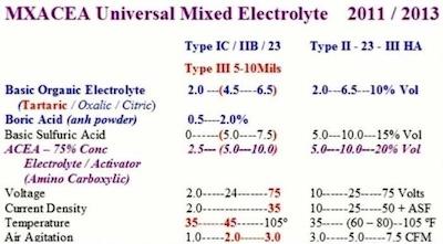 Figure 1. One Universal Electrolyte FormulationThis universal electrolyte and variable pulse along with eight key procedural requirements came to be known as the “complete spectrum approach,” beginning in 1990 and continuing to the present. Finally, selective brush anodizing was introduced using a super concentrated type IC-IIB- III and
Numerous anodizers and production facilities have made this electrolyte possible through their sincere professional technical support over more than 50 years of research in problem-solving situations. The following formulation represents only one condensed version of one universal mixed electrolyte for Type IC, II, IIB and III anodize. This electrolyte was also used for selective brush for all three types of anodize (Type 123).
This universal formulation was developed after reviewing several different process tanks in production. The ranges marked in red represent a formulation used for Type IC and heavy thickness hard anodize (10 Mils). The low sulfuric acid concentration and high tartaric acid concentration made this possible. The higher concentration Type II – 23 – III HA formulation was used for high production Type II and III anodize in the same anodize tank. The ACEA is an Amino Polycarboxylic Electrolyte Additive/Modifier based on a concentrated MAE Type additive along with amino acids.
Process Procedural Requirements: Key Secrets For Successful Anodizing
After working on numerous problem-solving situations and troubleshooting for various anodize facilities, various procedural requirements were developed4. These procedural requirements should be used for preparing Pulse – Step – Ramp and Run procedures for all types of anodize. Here is how they were presented at anodize workshops:
Actual process procedures and/or procedural parameters are the real heart of quality anodize. The key secrets included in this workshop date back 50 years, in some cases. They still remain the basis for most of the finest hard anodize procedures available. ATS was probably the first group to bring them all together for anodize seminars, training programs and workshops.
The process procedures presented in this workshop depend upon the strategic use of critical factors, requirements and technology which, when used together as a Complete Spectrum Package (in conjunction with a good electrolyte) during the ramp and run cycles will produce consistently excellent results. Critical requirements developed in part from problem-solving situations are listed below in the order of precedence and can be seen in real-time graphs at the end of this discussion.
- Activation – Voltage Pulse Early During Ramp (Detailed 3 Stage Pulse – 2012 Paper)
- Pulse-Step-Ramp (PSR)
- Increased Dwell Times (3-7) (For Proper Pore Structure Conditioning)
- Amperage Decay or Drop Off (ADO)
- Constant Current Density Ranging (CCDR)
- Process Time vs. Ampere Hours
- Real-Time Graphic Observation (monitoring for reproducibility)
- Current/Voltage Spikes or Deviations/CSD Discovery Leading to APCD
Activation – Voltage Pulse Early During Ramp:
Activating and maintaining activation is very important at the start of (and early in) the ramp cycle. This is accomplished by increasing the current density (5 10 ASF for Hard Anodize) within 10–30 seconds after positive bus bar contact in the anodize tank. The current should be slow pulsed 25–50% using anodic discharged surface activation (APCD – if available). Field-assisted dissolution is increased, producing an electropolish action activation at the surface, which can be helpful for all alloys, but is extremely critical on 7000 series. These alloys tend to set up corrosion cells very quickly before anodize is even initiated during the ramp cycle. This manual pulse early in the run is considered a secret technique and used by many top anodizers.
Pulse – Step – Ramp (Slow PSR Preferred):
Pulse-Ramp technology should be mandatory on all type II – III – 23 and 123 anodizing, in order to achieve maximum quality and efficiency along with additional energy savings. Pulse-Ramp should always be applied as Slow Pulse – Step – Ramp initiated during the ramp cycle. Slow pulse specifications have been proven acceptable for more than 30 years on all aluminum alloys with improved quality (hardness), efficiency (anodize time) and energy savings (KWH). An additional slower pulse system, which gives even greater time and energy savings, can be used on most aluminum alloys, after the specified slow – pulse – step – ramp and for the duration of the anodize run cycle. The current (amperage) is pulse ramped in the voltage mode, in 0.1–0.3 volt increments and in 2–15 second steps, which cannot be confused with the dwell periods. They may be referred to as small ramp steps and longer dwell periods or steps.
Increased Dwell Times (3-7):
Slow Pulse – Step – Ramp procedures must have dwell times or periods while running to constant current density. These dwell periods have been overlooked or thought not to be important due to the lack of a full understanding of the anodize pore structure development. They are, however, very important during the ramp cycle as related to final quality, efficiency and energy savings. The number and length of dwell periods for type II, 23 and type III anodize are as follows:
- Type II Clear Anodize: 2 – 4 Dwell Periods; 30 sec – 3 min dwell
- Dyed Black: 3 – 5 Dwell Periods; 30 sec – 3 min dwell
- Type 23 Hard Type II: 3 – 5 Dwell Periods; 30 sec – 3 min dwell
- Type III Hard Anodize: 4 – 10 Dwell Periods; 45 sec – 5 min dwell
- Type III Hard 3 – 10 mils:4 – 10 Dwell Periods; 1 – 10 – 20 min dwell
The number of dwell periods along with their times of duration play an important role in Amperage Decay (ADO), which is the secret to actual coating formation.
Amperage Decay / Drop Off (ADO):
The Amperage Decay or (ADO) is one of the most important factors/requirements necessary for maximum quality, efficiency and energy savings. It must be used on all Slow Pulse – Step – Ramp – Dwell Periods and throughout the anodize run cycle. The secret is: amperage must be controlled in the voltage mode in order to develop amperage decay; do not use the CC control knob!
Constant Current Density Ranging (CCDR):
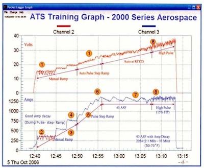 Figure 2. ATS Training Graph—2000 Series Aerospace.The current is Pulse – Step – Ramped by increasing voltage (voltage mode) until a calculated current (amperage) is reached, which represents a running constant current density dependent upon the square ft area in the tank and the required current density (ASF) for the alloy. For example – A tank load of 25 sq feet to be run at 40 ASF would be calculated and set for 1000 Amps (25 x 40 ASF) for the duration of the run. A steady constant current density should never be used in anodizing. The amperage must be allowed to drop off as it pulses within a range. To better define the procedure process, we will use the term Constant Current Density Ranging (CCDR). For example – If we are anodizing at 40 ASF, we may set the (ADO) at 10%. If the amperage is calculated at 1000 (representing 40 ASF) and set plus 5% (1050) and allowed to delay (drop off) 10% to 950 amps before manual or automatic reset to 1050 Amps, then we are anodizing at an average of 1000 Amps (40 ASF). Also, with the addition of pulse, we may open the CCDR by 25% while still anodizing at an average Current Density of 40 ASF, with increased energy savings. This CCD Ranging, (CCDR) or average CCD ranging (AVCDRG) is extremely important for the production of all type II – III – 23 and 123 anodic coatings. CCDR run in the voltage mode is a key secret sometimes overlooked by many anodizers.
Process Time vs. Ampere Hours:
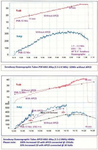 Figures 3 & 4. Sonabuoy Oceanographic Tubes-PSR 6061 Alloy (1.5-2.0 Mils) -52Min without APCD vs. Sonabuoy Oceanographic Tubes APCD 6061 Alloy (1.5-2.0Mils) 40Min.There are at least three ways to process anodize. These include Time, Final Voltage and Ampere Hours. Most loads are run strictly by time. However, Ampere hours is actually the best way to run the process, especially when pulse is used and may vary during the process run. When Pulse Ramp and Constant Current Density Ranging are used along with time, the addition of ampere hours will give very accurate final thickness results:
- Voltage Ramp to Control Current; Activation pulse can be added indicated in RED
- Initial Current (25% or 10ASF) – 5 Min.; Activation pulse can be added indicated in RED
- 3-4. Manual Control – Dwell Steps; ADO (Amp Drop off) occurs during dwell periods
- Pulse – Step – Ramp – Dwell; Automatic control if available
- 6-7. CCDR – Constant Current Density Ranging; Automatic control if available; Plus 5 – 10% ADO (Amp Drop off – Decay)
- Slow Pulse Reset during CCDR Run Cycle; Amp Hour Meter should be used with Pulse
(± 0.0001mil), allowing for the extremely tight tolerances of today’s critical components. The secret here is a consistent current density ramp with guaranteed repeatability.
Real Time Graphic Observation:
It cannot be overemphasized how important real-time graphic data loggers (see Figures 3 & 4) are for improving quality, efficiency (reduced time) and energy savings (reduced KWH). The operator can immediately see any problem that might occur during the process run. There is a permanent record for future evaluation along with a means for continued improvement on the next process run. No load should be run without at least a portable unit on line. They are inexpensive and the pay-off is fast with assured results. The key secret here is to find a person who really wants to learn anodizing, train him/her properly and give him/her a personal computer so he/she can access all of his/her production runs. This person will make and save you money.
Current/Voltage Spikes and Deviations/CSD Discovery Leading to APCD:
Capacitance shunt discharge (CSD) was first used to neutralize current and/or voltage spikes. This eventually led to the development of anodic pulse capacitance discharge (APCD) which is very unique. Please refer to the data logger graph, which illustrates it in operation, as more current is developed with no increase in voltage. Current and Voltage Spikes and/or Deviations can cause serious procedural problems and must be evaluated by good anodize training, experience, and technology. For example — A current increase during a ramp dwell period could be a potential burn. Voltage Spikes could be a malfunction in the power supply due to SCR Radical Misfiring. A definite ADO during a dwell period indicates good initial anodize coating formation during the ramp cycle.
Please compare the voltage and current values with APCD and without APCD on the data logger graphs (see Figures 3 and 4).
| Voltage | Without APCD | With APCD |
| 15V | 25–50 Amps | 300 Amps (min) |
| 20V | 150 Amps | 400 Amps |
| 30V | 340 Amps | 540 Amps (min) |
APCD disconnected after 30 Volts
Problem-Solving Situations/Troubleshooting Defects
The following represent defects, properties and control factors which were involved in problem-solving situations. Procedural requirements along with concentrated organic additive/modifiers also represent improvements and solutions to problem-solving and troubleshooting situations as follows:
- Smut, Powder and Burning; Reduced by Pulse – Step – Ramp plus concentrated additives/ modifiers
- Burning: Prevented by the Complete Spectrum Approach; Endothermic properties of concentrated additives/modifiers; Pulse – Step – Ramp and ADO; ADO during Constant Current Density Ranging CCDR
- Pits/Blisters (7000 Series); Tendency to Pit Reduced by PSR Activation @ 3–5 Volts
- Corrosion Resistance; Increased by RSR and Amperage Decay (ADO); (Due to better pore structure for sealing)
- Slow Anodize Formation Rate (Speed); Faster Anodize using PSR and CCDR; Controlled using amp hours during pulsed current
- Anodize Tank Temperature Range; Wider Range to 100º F+ using concentrated Chemistry and PSR; (Concentrated additives & modifiers increase heat absorption in pore structure)
- Poor quality (dull) color Anodize; Increased Dye Penetration using PSR +Dwell
- Pore Structure Development/Bonding Properties; PSR/Dwell times are keys to proper formation and development; PSR for Superior Adhesive Bonding Properties @ 5-10 Volt
- Final Microfinish; Improved due to PSR – Temperature; Increased concentration of additives and modifiers
- Power Savings (Lower KWH); Low Voltage / Higher Current / PSR, ADO, Dwell
The Balancing Act
The following balancing act5 found in another anodize workshop/paper can be very beneficial in troubleshooting situations. Please note how the many chemical and electrical control parameters affect the anodize formation process.
There are many different chemical products which can be used as electrolytes, but we will only consider sulfuric acid since it is the most common. However, the control parameters we will consider would be applicable to any electrolyte.
The basic electrolyte is composed of a certain concentration of sulfuric acid. The amount is determined by two important considerations: 1.) The ability of the solution to conduct electricity efficiently; and 2.) The ability of the electrolyte to dissolve the aluminum oxide coating. The balance that must be determined and maintained for consistency is that between formation and dissolution of the anodic coating. To do that, we must carefully control the parameters that affect that balance.
Chemical Parameters
The following diagram demonstrates how the different parameters affect the balance between formation and dissolution. By exercising strict control over these forces, we gain control of the type of coating we wish to achieve. We are then able to generate a coating from the simplest thin decorative film to the heaviest hard coat film.
Table 2. Illustration of how the different parameters affect the balance between formation and dissolution.
| Anodize Formation | Chemical Parameter | Anodize Dissolution |
| Lowering | Temperature | Raising |
| Lowering | Acid Concentration | Raising |
| Raising | Acid Agitation | Lowering |
| Lowering | Aluminum Concentration | Raising |
| Raising | Additives/Modifiers | Lowering |
| Heat absorption in pore structure | ||
| Promotes anodize formation rate at higher temperatures | ||
| Lowering | Contaminants | Raising |
Electrical parameters
The formation of the coating is dependent upon the flow of electrons, which is represented by current (not voltage). The chemical factors influence the flow of current and the chemical dissolution simultaneously as noted above. The electrical parameters primarily determine the formation of the anodic coating, but if the coating is not forming efficiently it is dissolving as a consequence of the chemical parameters.
Table 3. Illustration of how electrical parameters determine formation of the anodic coating.
| Anodize Formation | Electrical Parameter | Anodize Dissolution |
| Increasing | Contact | Decreasing |
| Increasing | -Current Density | Decreasing |
| Increasing | Current Distribution | Decreasing |
| Increasing | Pulse Step Ramp | Decreasing |
| Promotes formation at low voltage | ||
| Increasing | Voltage | Decreasing |
| Increasing | Time | Decreasing |
| Increasing | Metal Conductivity | Decreasing |
There will be other universal electrolytes that will be developed as they become necessary to meet present and future specifications. However, the problemsolving procedural requirements presented herein should become a part of all anodize processing.
References/ Footnotes
- Reynolds, U.S. Patent 2,743, 221 (1970)
- Working, K.C., U.S. Patent 3,434,943 (1969) F.C. Schaedel, U.S. Patent 3,418,222 (1968) F.C. Schaedel, U.S. Patent 4,152,221 (1979) Kjucaricek et al., U.S. Patent 4,879,018 (1989)
- C. Schaedel, proc NASF-2008 Realizing New Limits Using Anodic Discharged Surface Activation and Conditioning for Type III Anodize on All Alloys
- C. Schaedel, proc NASF 2011 The Leading Edge Guide to Top Quality Anodizing Using the Complete Spectrum Approach with One Universal Type I-II-III-(123) Mixed Electrolyte
- Richard Mahn proc AAC 2002 Anodizing Aluminum (The Balancing Act)
Fred Charles Schaedel is President of Alpha Process Systems in Westminster, California. Visit http://www.alphaprocess.com. He started Anodizing and Plating at Hudson Plating Works and Harshaw Chem. Co. in Cleveland, Ohio, in 1957. He has developed specialized anodize additive modifiers, and pulse ramp systems — including waveform technology — and established training programs in the anodizing industry dating back to 1962.