To help practicing electroplaters better cope with problems that occasionally occur in their plating lines, an attempt was made to analyze their causes and offer practical answers.
 N.V. Mandich and William SaasBecause of the large number of plating variables and the complexity of some electroplating systems, a generalized, systematic approach to troubleshooting is presented. For clarity, no theoretical explanations are offered, and technical language is used in the simplest, most straightforward form. A decorative nickel/chromium system is used as an example, with emphasis on the preplating and nickel electroplating step sequences. Troubleshooting of the final chromium electroplating step is detailed elsewhere.1
It is far better to avoid trouble by practicing close control than to have to remedy problems. The Chinese thought it wise to pay a doctor to keep them well, and the pay was withheld when illness occurred. The analogy with electroplating may not be immediately obvious, but, logically, control of electroplating operations by a master plater, or a trained laboratory staff, affords insurance against troubles that may cause costly rejects or shutdowns.
Editor’s note: This article was written in June 2000.
Successful decorative electroplating is not for amateurs. There are many technical pitfalls, some of which can be solved by book learning, but others can be overcome only through experience. A master plater, and even more, the troubleshooter, is one-third artist, one-third technician, and one-third technologist—a rare breed indeed! One must have an integrated worldview of the deposition process as a whole, not just the electroplating steps. Base metal composition, heat treatment, cleaning and activation cycles, intermediate electroplated layers, the addition agent system(s) employed, etc., are all factors that can affect the appearance and properties of the final decorative deposits. Despite this, it is not witchcraft. Many dedicated scientists and practical technologists have spent years unraveling the solutions to many of these mysteries using established scientific methods.
Mysteries indeed remain and likely always will, but the true expert masterplater has studied the technical literature and has solutions to many problems at his fingertips. True, it may appear magical, but advanced technology will seem magical to persons lacking the broad expertise needed. Decorative NiCr electroplating is no exception, and while it may conceptually seem a straightforward type of electroplating, it can, in reality, often be rather challenging.
Why, then, is there still so much mystery surrounding the troubleshooting of, for example, bright, decorative nickel electroplating installations? There are at least eight reasons:
1. Nickel is perhaps the most used and versatile metal in the electroplater’s repertoire. It has been in use for more than 125 years. It is an essential element of any Cu/Ni/Cr or Ni/Cr decorative system from both practical and theoretical perspectives. Advances in Ni electroplating technology have expanded the process's utility and value while increasing the diversity and complexity of electroplating lines. The quality of the base metal and the nickel thickness have been kept at barely acceptable levels. This, in turn, maximized the speed of electroplating lines, current densities, and brightener concentrations, thereby artificially making the process more difficult to control. The need for reliable technical information about electroplating processes is more critical than ever.
2. Rack electroplated, bright nickel is seldom used alone as a final finish. It is usually applied in combination with one or more other metallic deposits; for example, as part of a series that can include cyanide, acid copper, semibright nickel, bright nickel, particle nickel, and chromium electroplated layers. Consequently, this multiplicity of electrodeposits and processing steps inevitably contributes to the system's complexity and to the concomitant troubleshooting.
3. The bright nickel bath itself contains several ingredients, including multiple addition agents used to force optimum leveling and brightness. Any journeyman troubleshooter can testify to the geometrical increase in difficulty of controlling any process bath as the number of components increases. All this makes problem-solving rather more complicated than just locating a given problem in the left-hand side of a column on a troubleshooting chart and matching it to its unique cause in the right-hand side, where general or most common answers are given.
4. Many faults that occur early in the processing cycle are not detectable on parts until they are at or near the end of the complete cycle. The most obvious example of this is inadequate cleaning that is not evident on a part until after it is electroplated with bright nickel. This lag effect complicates pinpointing the true source of trouble.
5. To further complicate matters, the same electroplating defect can result from several different sources. Of course, all electrodeposition baths exhibit this source-identification problem to some degree, but perhaps few to the extent of a bright nickel electroplating solution. For nickel, usually several possible causes can yield any given imperfection. Thus, matching problems with their causes is not as simple as it sometimes appears.
6. Bright nickel electroplating is an unforgiving and sensitive process. Many minor faults that are invisible to all but the most discriminating eye can significantly affect the quality of the final finish. Likewise, the electrolyte has no inherent cleaning ability of its own, so there is very little room for error in the pretreatment cycle compared with some other finishing processes.
7. Some problems can go undetected for some time before they affect the quality to the point where rejects occur. For example, it may take several hours or days for a deficiency in the cleaning cycle to allow enough impurities or soil to enter the nickel electroplating solution to cause noticeable rejects. Such delayed effects as this can make it acutely difficult to identify the real source of trouble.
8. At times, more often than not, suppliers of proprietary nickel electroplating processes have not been especially forthright in passing on troubleshooting and technical service information to finishers. This lack of information is generally a carryover from the days when suppliers passed on only a minimum of operating information to customers, believing that it would increase their worth and importance in customers’ eyes.
Rationale
Unfortunately, there is a lack of worthwhile articles offering an extended discussion of essential practical troubleshooting methodology. There are two noteworthy exceptions, however, that comprehensively address the troubleshooting of bright nickel electroplating installations.2,3 Nevertheless, only relatively few other references have properly emphasized what must be done to overcome the natural complicating effect that the above considerations have on troubleshooting situations. Instead, troubleshooting articles usually consist of extensive lists of faults, causes, and remedies for bright nickel processing lines, without describing an orderly, systematic approach to troubleshooting in general.
This does not mean that these sources of information are inconsequential. They can be consulted and used in all problem-solving situations. Attempting to use them, however, without systematically narrowing the scope of investigation can be inefficient and time-consuming. Time is a precious commodity when electroplating lines are down. Minimizing the scope of a troubleshooting investigation requires generating an essential-questions questionnaire. This helps focus the investigative effort toward those steps in the total processing cycle that are the most probable location(s) of problems. A secondary benefit of this approach is that it organizes the thought process in a way that eliminates much of the unnecessary mystique, fiction, and sometimes drama associated with troubleshooting and problem-solving (TPS) electroplating installations.
Clearly, because no two electroplating installations are the same, there is no such thing as a universal questionnaire that applies to every electroplating production line. Undoubtedly, certain questions apply in every case, but others apply only to a given installation. Accordingly, each plant must generate its own list of questions that consolidates both universally applicable matters and idiosyncratic questions unique to the given installation and the parts processed.
Design of the troubleshooting process.
A series of 16 suggested basic steps is offered, with 8 presented in this installment. They should prove helpful in generating such a questionnaire, one that will most effectively reduce the time needed to identify and resolve problems.
Table 1: Troubleshooting Methodology
- Identify the problem.
- Define the problem:
- Process problem?
- Operational (processing) problem?
- Correct the problem.
- Test solution of problem.
- Record corrective steps.
- Set up procedure to prevent recurrence.
1. Confirm the existence of a problem
Random occurrences of defects should not be mistaken for typical production performance. Once it has been confirmed that there is a problem, the extent of the problem should be identified.
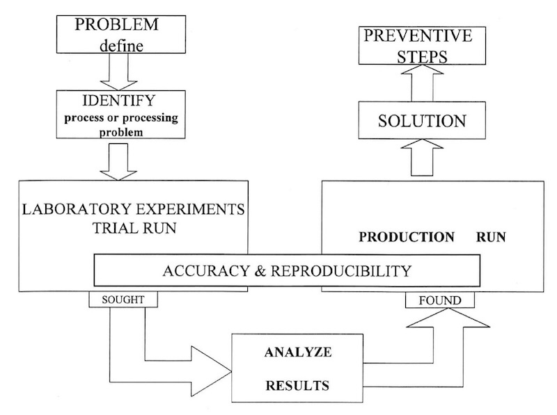
The recommended objective analytical approach to troubleshooting of electroplating processes is vital, both for the troubleshooter/problem solver and for training and teaching plant personnel to troubleshoot their own processes.4 This is described in general form in the figure. The causes of problems can be divided into two general categories: process problems and operational problems. For this discussion, process problems are defined as deviations from the recommended control range of solution chemistry. It is important, while searching for solutions to a problem, to keep in mind that something has changed. The obvious task is to pinpoint what has been changed, and then develop a remedial response. On the other hand, operational problems can be outlined as defects initiated from sources other than the electroplating bath chemistry itself. The table lists six steps of the troubleshooting methodology, providing a broad yet systematic approach to troubleshooting electroplating lines.
2. Defining the type of problem
Despite all the previously mentioned factors unique to decorative nickel electroplating that complicate troubleshooting efforts, there is only a finite number of defects that occur on a bright nickel electroplating line. The following is a partial list of problems that covers more than 95 percent of those commonly encountered:
- Stains, hazes, clouds, or streaked patterns
- Darkness and/or dullness of the asplated deposit
- Pitting
- Roughness, on a micro or macro scale
- Poor adhesion, laminations, peeling, and blistering
- Poor coverage of nickel or chromium deposits in low-current-density areas
- Brittleness and/or “burning” of the plated finish
- Reduced cathodic and/or anodic efficiency and low electroplating speed
- Insufficient leveling
- Orange peel
The type of problem must be defined before consulting the reference information that lists the various causes and remedies of many electroplating defects, or one’s own experience.
3. Extent to which the problem exists
Once the existence of a problem is confirmed, the next step is to determine its extent. Is it evident to the same degree on all processed parts, or just a few? Unless there is a gross malfunction of the line, problems rarely occur on every piece; however, when this happens, it usually results from a single major fault, such as one of the rectifiers being turned off, or a temperature being too low or too high in one of the processing tanks.
In addition, it is important to determine where on the part the defect can be seen: on all surfaces, on horizontal surfaces, or just on vertical surfaces? The more evident the problem is across all surfaces, the more likely it is to be caused by a single, often major, source. Likewise, problems that occur only on horizontal surfaces usually result from solids in one of the processing tanks—generally either the copper tank (if copper is part of the total processing line) or the nickel tank. Another possibility is that the resulting roughness is caused by lifting parts through a layer of soil that has collected on top of one of the processing tanks, most likely in one of the cleaning tanks.
It is also important to determine at which current densities (CDs) the problem is most pronounced. Can it be seen at all current densities? Just at high CD or just at low CD? As a rule, problems evident at all CDs are caused by faults in a processing step other than one of the plating tanks.
4. Where on the rack does the defect occur?
If parts are rack-processed, is it at the top, the bottom, the center, or at the corners? If the problem occurs at a corner of a plating rack (fixture), is it the corner that exits the various processing tanks first (i.e., the leading edge) or last (i.e., the trailing edge)? Problems that occur only on parts taken from the top or bottom of a rack, but are not necessarily density-specific, usually result from insufficient or excessive time in a pretreatment step. Another possibility, when a problem is evident only in parts taken from the top of a rack, is that the solution level in one of the processing tanks is too low. Problems that occur only on parts taken from the center of a rack are generally low-current-density-related and usually result from a problem originating in one of the electrified processing steps: an electrocleaner, an electrolytic activator, or an electroplating tank.
Problems that occur on parts racked in the leading edge area of a plating rack (fixture) generally result from electrical faults in the entry area of a chromium electroplating tank.5 Similarly, defects evident on parts racked in the trailing edge area are usually caused by electrical problems in the exit area of a nickel plating tank. Reversing the rack's position after it exits the nickel tank but before it enters the chromium tank will usually confirm these suspicions. If a leading-edge fault persists in the same area on the rack after reversing the leading and trailing edges, it usually indicates the problem is in the chromium tank. On the other hand, if the problem location shifts when reversing the rack position, the nickel plating tank is usually the source. This list of questions is, of course, not all-inclusive. It should be complete enough, however, to illustrate the type of qualifying questions to ask to properly define the difficulty so that problem-solving efforts can be more efficient.
The easiest problem to solve is the one that occurs on every processed part, but this rarely happens. Generally, a problem is evident only in a portion of the production parts. As a result, a systematic, analytical approach is necessary. The point in the total processing cycle where the fault can be seen must be identified; then work backwards from this point, examining each step of the cycle to pinpoint the prime location and cause of the trouble.
5. Selecting the best testing methods
Tests must be selected that will provide the greatest measure of information, while expending the fewest resources. This minimizes costs and simplifies data analysis. For example, it is often helpful to switch the position of two racks in the cycle to determine the effect of skipping a given step in the total cycle. In these cases, it is most efficient to couple the testing of eliminating one step in the total cycle with the effect of doubling the time spent on another processing step. After identifying these two steps, the racks can be switched back to these portions of the cycle.
In general, plating defects that are current-density specific result from something that is out of specification in one of the electrified processing steps. The easiest way to determine whether a given step in the cycle is causing the current-density-related problem is to reposition the parts on the plating fixture during this portion of the cycle. In these cases, it is obviously not necessary to move entire racks. A simple transfer of parts from one location on a rack to another on the same rack will do (e.g., from a high CD area to a low CD area, or from the front to the back of the rack). If the problem location changes as the part's rack location changes, it is reasonable to assume that something is happening (or not happening) in one of the electrolytic steps ahead of this portion of the cycle and causing the defect. Likewise, if the defect does not move with the part, but remains in the same location, it is reasonable to assume that the processing step in question is causing the difficulty, or at least contributing to it.
Another useful test is simply to rotate the part 180° degrees to transform the top surface before a given step to the bottom surface. This is an especially practical approach in instances where shelf roughness is a problem, and the task is to determine which step in the total cycle is creating or introducing it. In these cases, it is easy to determine whether a single step is responsible for the roughness by rotating a part while it is in the tank. The part should be examined after it has completed enough of the total cycle to the point where the defect is visible. Obviously, this same approach will test specific process steps for pitting tendencies.
Changing the location of a part on a rack, or its position, is not always the best way to test whether given steps in the processing cycle are causing difficulties. In cases where hazes or cloud patterns are evident on parts after plating, the pretreatment portion of the cycle is often the source of trouble. The most effective way to screen the individual steps of the pretreatment cycle is to partially wipe an area on a part just before it enters the questionable tank. If the haze or cloud cannot be seen where the part has been wiped but is still evident in the adjacent areas, it is logical to assume that the pretreatment cycle is not removing a deleterious residual film responsible for the haze or cloud. Using a white paper towel or rag makes it easier to observe when the hand wiping removes soil or smut. Correspondingly, the wiping process must begin immediately ahead of the first plating tank after which the defect can be seen, then systematically worked backwards from this point to identify the step in the total cycle that is responsible for the residual film. If wiping with a paper towel or rag does not affect the haze or cloud, the process must be repeated with more aggressive cleaning, such as with a clean Scotchbrite™ pad. If this eliminates the problem, it is safe to assume that the interfering film is quite tenacious, and a more vigorous pretreatment cycle should be considered.
If wiping parts with a Scotchbrite™ pad does not remove the haze or cloud, it is more than likely that the problem is notduet to anything occurring in the preplate portion of the plating cycle. Instead, the plating and post-plating portions of the line should be evaluated.
6. Variation of one parameter at a time
This is one of the most important guidelines to follow. Admittedly, this is most difficult to do in the face of extreme pressure to restore full production capability as rapidly as possible. Nevertheless, changing conditions one item at a time is the only method to obtain a positive answer to a problem. Changing several things at once may more quickly eliminate the difficulty, but it does not provide an exact identification of which change had what effect on overall quality. In other words, it does nothing that will lead to a permanent solution to the problem. Worse than that, it does nothing that will simplify solving the same problem the next time it occurs.
7. Maintaining limited production
Problem solving is difficult, if not impossible, without processing actual production parts, even when it involves generating a limited number of rejects. Moreover, problem-solving is much easier when workflows are not interrupted in the line. Repeatedly filling and emptying a processing line may produce fewer rejected parts, but it also introduces more variables that complicate problem-solving. This is notably true in cases of electrical problems. The only way to properly investigate them is by testing when there is a rack at each station in the line. Operating with a series of empty stations will produce entirely different results.
Another approach to restoring at least limited production is to return to a process cycle that has worked in the past. If this cannot be done, experiments can be conducted with different processing cycles, such as double cleaning and/or acid dipping, or with longer plating times. The extent to which these changes can be carried out depends upon the physical limitations of the line involved. Another possibility is to operate with fewer parts on each plating fixture or workbar. There are times when problems are evident only in parts of a certain size or configuration. In these cases, another option is to run as many parts as possible that can be processed without problems, while simultaneously allowing processing of a limited number of parts that exhibit the given defect. Otherwise, there is no method to measure progress. Of course, the long-term goal is to resume normal production. In the short term, however, operating with an altered cycle that allows limited production is better and often less traumatic than losing production entirely.
8. Offline testing
When feasible, as many things as possible should be tested offline. It should include as many steps in the total cycle as are workable, including often-overlooked rinse tanks and even drying steps, if they appear to affect the observed defect.
The most important consideration is to duplicate production conditions as closely as possible. In particular, it is critical to match dwell times, traveling times above the various processing tanks, and transfer times between tanks. It is also important to match the level of agitation during the online processing of pieces. Often, the easiest way to isolate a single processing step, while duplicating the remainder of the production cycle (including dwell times, transfer times, CDs, etc.), is to use an auxiliary, small, offline processing tank. A tank, or even a lined 55-gal drum, can be placed next to the production tank to be bypassed during a given test. The test consists of removing one or more parts from a rack as it is about to enter the tank in question, then running them in the auxiliary tank instead, while carefully matching the processing parameters. As the rack exits the regular processing tank, the parts are removed from the test tank and replaced in their original locations on the production fixture. The location of each piece processed in this manner should be marked, and the number of the workbar or hanger to which the rack is fixed should be recorded.
9. Laboratory plating tests
The Hull Cell is an important and useful tool for day-to-day solution control, especially for troubleshooting. It is an extremely powerful test method, despite its basic simplicity, especially when compared with other electroplating controls, such as titration, electrochemical instrumental methods, or spectrophotometry, all of which usually measure only one variable at a time. A single Hull Cell (HC) test, or short test series, can potentially show the limits of acceptable electroplating current density ranges, detect the presence and amounts of organic and inorganic impurities, assess leveling and throwing power, approximate the concentrations of primary constituents, and determine addition agent concentrations. It can also be used to control deposit morphology, alloy composition as a function of current density, agitation effects, average cathode efficiency, evaluate covering power of competitive electroplating systems, appraise competitive additive systems as to their brightness, electroplating range, heat stability, life, compatibility, etc., as well as other variables. One does not need to be confined only to the visual examinations of HC panels. For example, the hardness of the deposit can be tested under different electroplating conditions (e.g., CD) of interest. Similarly, the deposition thickness, porosity, throwing power, and many other properties can be tested on the panel under different, defined conditions.
Producing and interpreting Hull Cell or other electroplating cell panels requires only an average amount of skill, but at least a fair amount of experience. For this reason, line operators or foremen should be encouraged to collect and preserve panels exhibiting various faults for future reference.
The tests in the Hull Cell and similar testing cells are, in essence, qualitative procedures that provide semiquantitative or quantitative answers. The qualitative answers are obtained from observations of plated panels. For example, when the electroplating bright range is found to be reduced in the low-CD area of the panel, the concentrations of brightening addition agents are likely low, and adjustments are needed. Similarly, a rough, dark, and irregular appearance in high CD areas may indicate metallic impurities. Pitted deposits often suggest thatfilme formation reduces surface tension, which can be achieved by adding wetting agents to the bath. Cracked deposits often indicate the presence of excessive addition agents or a high concentration of decomposed addition agents. Poor coverage in low-CD areas can result from the same fault.
Managers and supervisors of plating operations need not actually perform HC plating tests themselves, but they should nevertheless be able to discuss and interpret the results of such tests intelligently.
10. Selection of the best testing methods
The most effective test is the one that provides quick results and closely duplicates the problem seen in full production. This prevents wasted time and effort “chasing ghosts.” As mentioned before, ideally, when testing, the regular processing cycle should be used for everything but the individual cycle step under investigation.
If offline testing does not reproduce the problem with standard test samples (e.g., Hull Cell panels), running production parts in an auxiliary tank is appropriate. If parts are too large to allow this, the next best alternative is to run small sections cut from production parts, using racking geometry that approximates production conditions. If the problem can be seen at this point, logic suggests it cannot result from any of the processing steps that follow the one under study. In addition, since the fault was not apparent on another base metal (i.e., the Hull Cell stock), a parameter may be within a range that affects only certain base metals. An example would be a temperature, pH, or concentration of the cleaner(s) that is too high. It is unlikely to have a measurable effect on steel-based metal parts, but it could be significant when processing copper, bronze, brass, or diecast parts with the same cleaner.
If, alas, offline testing still cannot reproduce the defect, the next step is to run parts of known-quality base metal on the production line in place of regular parts. Hull Cell panels are usually accessible and offer the additional advantage of allowing the complete elimination of the cleaning cycle. The thin zinc coating on the panels can easily be removed in a small volume of freshly made-up acid. Wiping parts with a clean, wet sponge or towel removes any surface smut. It provides a reproducible part that can be inserted into the production line immediately ahead of any processing tanks. If this is properly done and the problem is visible in the Hull Cell stock, it is safe to assume the tank under study is the source of the difficulty.
11. Recognition of the most influential parameters
It should be remembered that all parameters measurable on a processing line do not have equal impact on quality. In a nickel plating solution, for example, the parameters that have the greatest effect on performance are those that can change the quickest: pH, temperature, agitation patterns, concentration of the secondary brightener portion of the addition agent system, current to the cathode, entry and exit currents on nickel and chromium plating tanks, etc. Accordingly, these are the factors to examine first when faced with a troubleshooting/problem-solving situation. Only after examining these aspects is there reason to check the other operating parameters.
It is important to keep in mind the degree of change each of these parameters can undergo before it has a significant impact on line performance. For example, a 10 percent change in pH or temperature will have a much more dramatic effect on quality than a 10 percent change in boric acid concentration.
12. Records must be diligently documented and maintained
The results of all tests and observations, including modifications to the total cycle that have no apparent effect on the problem, must be recorded. Production parts must be labeled in a manner that reflects the differences in processing cycles, or steps that have been screened, regardless of whether they have a noticeable effect on performance. It must be remembered that it is often just as valuable to know which steps have the least effect on total performance as it is to know which ones have the greatest effect. Also, it should be kept in mind that changing just one or two steps in a long electroplating cycle seldom solves most troubleshooting situations. Usually, several changes must be made before a problem can be accurately identified and the cycle adjusted to eliminate substandard work. This must be done in a stepwise fashion, and the only way to keep track of each modification is to document it.
13. Objectivity
Experience has repeatedly demonstrated that independent thinking is essential, allowing one to step back from the proverbial trees to see the forest. The troubleshooter/problem-solver must be objective. The problemsolver cannot approach any troubleshooting situation with the attitude of already knowing the cause of a particular problem before starting any tests. It is important to make the most efficient use of prior troubleshooting experience, but not at the expense of objectivity. To solve a problem permanently, the troubleshooter must identify and treat the cause, not the symptom. This can be accomplished only by maintaining an unbiased point of view.
14. Domino and Additive Effects
In addition to the previously mentioned time lag and delayed effects, there is always the possibility of experiencing additive and/or domino effects. In the former case, each separate process step or bath condition is slightly out of balance,n such that it interacts with other steps to produce the overall defect. An example would be a weak acid dip after nickel plating, plus insufficient activation at the beginning of the chromium bath, resulting in passive chromium deposits (“white wash”).
In domino effects, problems in one process step can negatively affect the next process step. An example would be overcleaning in the anodic electrocleaner, which can darken or even slightly etch parts being processed. This, in turn, can lead to an (erroneous) overdose of a brightener, which produces a residual brightener film on insufficiently rinsed parts. If activation cannot completely remove this film, the final chromium deposit can exhibit “white wash” chromium hazes. These simple examples show that the entire process must be methodically checked. If not, problems might only be partially fixed, a “Band-Aid” approach, soon to reappear or change for the worse. Some problems are fairly simple and can be logically solved with standard background knowledge. For other problems, only the most skilled experts may observe and connect the discrete bits of data into quick, practical, and workable solutions.
15. Knowledge
Persons in charge of electroplating departments, electroplating engineers and chemists—even ambitious masterplaters—must be at the forefront of knowledge in their fields of expertise. Book knowledge is not reserved solely for academicians. It is expected of them to be up-to-date, even ahead, of their own staff experts. Those who expound the virtues of a traditional electroplating technique will be regarded as passé by coworkers, or worse, by their superiors as well. One essential area of knowledge is “hands-on” knowledge, supported by close familiarity with recent technologies. Too many electroplating engineers, chemists, and masterplaters subscribe to old myths that previous studies have dispelled. They need to keep up with the recent technical literature, therefore, or they will be purveyors of obsolete traditions. Clearly, they need to be well -ersed and proficient in the latest electroplating developments and new and emerging technologies. If, for example, a marketing department asks about the merits of composite deposits, or pulsed reverse techniques, or trivalent vs. hexavalent decorative chromium electroplating, one cannot beg off with a “Let me check at the library and get back to you later.”
The most effective problem solvers possess general knowledge across many fields, especially a solid foundation in chemistry, engineering, metallurgy, manufacturing, and electronics. This aids them not only in seeing the “big picture,” but also in conversing with engineers, R&D personnel, or management in terms they understand.
An in-house library of relevant books, technical papers, and troubleshooting reference information must be established, developed, and kept current. While there are 512 books published on chromium electroplating, there are only two on nickel electroplating: 12 and 13 (one is out of print, 13). Fortunately, there is an outstanding book available on the subject.12 Also, books on analytical and process control1423 must be available, as well as books dealing with fundamentals.2429
16. Preventive maintenance
No worthwhile discussion of troubleshooting concepts would be complete without stressing the importance of preventive maintenance. It has been proven over and over that production difficulties and high operating costs are inversely proportional to the degree of overall control and preventive maintenance that is exercised. In other words, the more time and effort are put into catching and solving problems. At the same time, the smaller they are, the less difficulty there will be in maintaining a high-quality, efficient operation. A few simple things can be done to prevent problems before they happen:
- Timely recording of all additions to every tank in the processing cycle. This should include dates when tanks are replaced and made up fresh, as well as when the electroplating tanks are treated to remove various impurities. Having this information is extremely beneficial. It streamlines troubleshooting and provides very useful cost analysis information, even when there are no problems.
- Good housekeeping must be diligently maintained throughout the plant, especially in the areas near the processing line(s). This will minimize the possibility of foreign matter accidentally entering any of the tanks.
- A reference file of HC panels and parts that illustrate certain problems and their remedies. Not only is such a file an invaluable aid during troubleshooting, but it is also very helpful as a training tool for new employees.
- Different aspects of the processing line must be routinely scrutinized and reported. Most finishers agree that incorporating simple yet essential records, such as those listed in Table 2, into their plant practices is highly beneficial.
Finally, the obvious question is: why aren’t effective, modern preventive and troubleshooting systems, complemented with current knowledge, universally applied? It is our experience that many platers become mired in the status quo because they and/or their employees prefer a known past to an unknown future. Unfortunately, resistance to change is nearly universal. Many platers either prefer not to use the basic electroplating principles, have forgotten them, or do not know them, because the first suspicion of a problem usually results in a phone call to the current supplier of electroplating chemicals, a potential supplier, or a consultant, not necessarily in that order.
In certain situations, the problems can persist despite efforts by the masterplater and others involved in troubleshooting. Rather than keeping the plating lines down and/or generating rejects, it may become necessary to call in an outside master consultant who can often provide independent and unbiased judgment and present new ideas and a fresh approach.
Table 2: Routine Control Procedure
| Control Item | Frequency of Control |
| Bath Analysis | Weekly |
| Plating Tests | Weekly (more often under heavy production) |
| Pretreatment solutions | Twice weekly |
| Solution levels | Each shift |
| Temperature controllers | Each shift |
| Ammeters/Voltmeters | Each shift |
| Addition agent feeders | Each shift |
| Anode baskets | Twice weekly |
| pH of Nickel solution | Each shift |
| Solution flow through filter | Each shift |
| Uniformity of agitation | Each shift |
Conclusions
A worthwhile, methodical approach to troubleshooting electroplating problems begins with the understanding that “No effect takes place without a cause.”30 This quotation is from Michael Faraday, who literally galvanized the Industrial Revolution at the beginning of the 19th century. This is another way of saying, “The defect is the symptom, not the problem.” This principle is the most important for electroplaters to absorb. Understanding this principle changes the “tank jockey” into a skillful, professional finisher. The skilled masterplater, when faced with a problem, considers: “What are the causes of these rejects? Why is the finishing bad today when it was good yesterday?” Then the masterplater searches for and finds the causes, finds the answers, and then implements corrections.
Efficient line handling and troubleshooting decorative electroplating installations, if done properly, need not be complex or unduly intricate. First, the problem's existence and type must be identified. The next step is to determine whether it is a process or an operational problem. Once this question is answered accurately, the search must begin to disclose the causes, find the corrective answers, test them, implement corrections, and, finally, set up a foolproof mechanism to prevent future problems from the same source. The single most important rationale is to establish and follow a logical procedure in analyzing the totality of the circumstances. This can be thought of, figuratively, as drawing up a road map that creates a series of forks. At each fork, one or more questions should be asked. The answers to the questions dictate which of the two paths to follow. As in the classical programmed instruction model, if the selected path does not lead to the desired result, one can return to the last successful fork on that path. This process can be continued until all the sources of difficulty are identified and all the necessary corrective steps are taken to restore high-quality, profitable, error-free electroplating. This approach must be used when troubleshooting electroplating systems to achieve consistently high-quality, reliable production results.
Summation of Troubleshooting Technique
The general troubleshooting technique can be outlined in six basic steps. Each step must be taken in sequence as a logical progression:
- Analysis—an evaluation of the available data to identify the existence of a problem.
- Synthesis—the development of a definition, probable causes of the problem, and suggestions for the corrective measures required.
- Testing—laboratory experiments, followed by small-scale pilot or production runs to test not only the solution of the problem, but the reproducibility of the solution as well.
- Implementation—incorporation of the actual permanent corrective procedure into normal shop practice.
- To minimize future problems, an effective preventive maintenance program should be established.
- Personnel training program—all personnel involved, directly or indirectly, in electroplating operations should be trained in all technical aspects of the job, including the all-important prevention steps.
References
- V. Mandich, Metal Fin., 97(6) 100; 97(7) 42; 97(8) 42; 97(9) 79; 97(10) 30 (1999).
- Gianelos, Plat. and Surf. Fin., 64(8) 32; 64(9) 32;64(10) 23 (1977).
- Guernsey, ibid, 63(2) 38; 63(3) 44 (1976).
- V. Mandich, AESF 87th Tech. Conf., Session E, Cincinnati, OH (1999).
- V.Mandich, Plat. and Surf. Fin., 85, 91 (1998).
- D. Greenwood, Hard Chromium Electroplating, 3rd ed., Robert Draper Ltd., Teddington, UK, 1984.
- Morisset, Chromium Electroplating, Robert Draper Ltd., Teddington, UK, 1954.
- Weiner & A. Walmsley, Chromium Electroplating, Finishing Publications, Ltd., Teddington, UK, 1980.
- K. Guffie, The Handbook of Hard Chromium Electroplating, Gardner Publ., Cincinnati, OH, 1986.
- Dubpernel, Electrodeposition of Chromium from Chromic Acid Solution, Pergamon Press, New York, NY, 1977.
- Peger, Chrome Electroplating Simplified, 4th ed, Hard Chrome Electroplating Consultants, Cleveland, OH, 1981.
- K. Dennis & A. Such, Nickel and Chromium Electroplating, 3rd ed., Woodhead Publishing Ltd., Cambridge, UK, 1993.
- Brugger, Nickel Plating, Robert Draper Ltd., Teddington, UK, 1966.
- Nohse, The Hull Cell, Robert Draper Ltd., Teddington, UK, 1970.
- E. Langford, Analysis of Electroplating and Related Solutions, Electrodeposition and Metal Finishing, Teddington, UK, 1951.
- G. Foulke & F.E. Crane, Electroplaters Process Control Handbook, Van Nostrand, New York, NY, 1963.
- F. Bogenschutz & U. George, Analysis and Testing, Finishing Publications Ltd., Teddington, UK, 1985.
- Metal Finishing Guidebook, Vol. 95, No. 1A, Elsevier Publishing, New York, NY, 1998.
- The Canning Handbook, 23rd ed., W. Canning Ltd., Birmingham, UK, 1982.
- Tables and Operating Data for Electroplaters, Portcullis Press, Redhill, UK, 1975.
- B. Saltonstall in Electroplating Engineering Handbook, 3rd ed., A.K. Graham, Ed., 1973; Ch. 8.
- J. Durney, Electroplating Engineering Handbook, 4th ed., Van Nostrand, New York, NY, 1984; Ch. 8.
- Armet, The Modern Electroplating Manual, R. Draper Ltd., Teddington, UK, 1965.
- Blum & G.B. Hogaboom, Principles of Electroplating and Electroforming, 3rd ed., McGraw-Hill, New York, NY, 1949.
- Raub & K. Muller, Fundamentals of Electrodeposition, Elsevier Publ., New York, NY, 1967.
- A. Lowenheim, Electroplating, McGraw-Hill, New York, NY, 1978.
- A. Lowenheim, Modern Electroplating, 3rd ed., Wiley, New York, NY, 1974.
- N. West, Electrodeposition and Corrosion Processes, Van Nostrand Reinhold, London, 1971.
- Dini, Electrodeposition, Noyes Publications, Park Ridge, NJ, 1993.
- Pearce Williams, Michael Faraday, Libr. of Congress Catalog Card No. 6519542, p. 22.
About the Authors
Dr. N.V. Mandich, CEF, FIMF, is president of HBM Electrochemical & Engineering Co., 2800 Bernice Road, Lansing, IL 60438. He holds a DiplIng degree in chemical engineering from the University of Belgrade, Yugoslavia, an M.Sc. in theoretical chemistry from Roosevelt University, Chicago, and a Ph.D. in applied electrochemical engineering from Aston University, England. He is an AESF-certified instructor and a member of the AESF Hard Chromium and Pulse Electrodeposition Electroplating Committees, and a Fellow of the Institute of Metal Finishing. He twice received the AESF Board Recognition Award (1991, 1995) and two silver medals for best published research papers (1997). He has published nearly 100 papers, 6 book chapters, and has 12 U.S. patents published or submitted.
William J. Saas is president and owner of Taskem, Inc., a manufacturer of proprietary products to the metal finishing industry based in Cleveland, OH. He has been active in the metal finishing industry for more than 40 years. He has worked as a plater and as a supplier in almost all aspects of metal finishing. He holds a BS in chemical engineering and an MBA from Case Institute of Technology. He has been a member of the Cleveland Branch of AESF for 35 years, served on the Technical Education Board for 7 years, and is an active speaker at AESF Branch meetings. Saas recently completed a three-year appointment as a trustee for the Metal Finishing Suppliers Association (MFSA), and currently serves as their representative to the Government Advisory Committee (GAC), which he also chairs. He has also served as one of six Industry Representatives to the Metal Finishing Sector of the Common Sense Initiative for the past five and one-half years, a reinvention of the program created by the EPA.