High-frequency and high-current pulse plating, as well as ultrasonic agitation, have been used to improve the smoothness and microhardness of copper coatings produced by electroplating from a sulfate bath in the absence of brightening agents.
 Dr. Peter Kristof and Dr. Mark PritzkerBy carrying out pulse reversal plating at higher pulse frequencies (200 kHz) than have previously been reported for copper plating, coatings have been produced with VHN microhardness values (50 g load) slightly above 200, normally achievable only with the addition of brightening agents. Pulse reversal plating has consistently been found to produce a smoother and harder deposit than pulsed current plating. The best results have been achieved by combining an ultrasonic field having a strength of 60 watts with current reversal plating at 200 kHz, 80 percent duty cycle, and 10 A/dm2 average cathodic current density. This yielded a deposit with a microhardness of 230 VHN and a mirror-smooth finish without having to do any mechanical polishing.
The use of pulsed current for copper electrodeposition has received much attention in recent years for improvement of some of the mechanical properties13 of the deposit as a result of minimizing the number of cracks in the microstructure4 and producing a more uniform deposit thickness.5
Note: this paper was originally published in 1998.
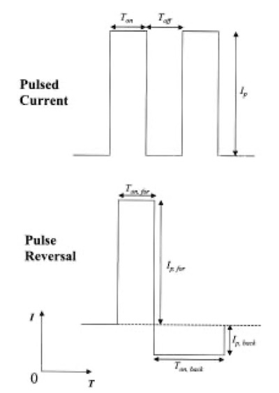 Fig. 1—Pulsed current and pulse reversal waveforms used.The conditions that typically have been used in pulsed plating of copper are pulse lengths on the order of milliseconds or longer and peak currents only slightly higher than those used in DC plating. Previous work has shown that the copper deposits still remain relatively rough at low frequencies on the order of 10 Hz. If frequencies on the order of 10 kHz can be reached, however, then very smooth deposits can be produced.6 The greater the frequency of the applied pulse, the thinner the diffusion layer becomes adjacent to the cathode. This transforms the entire surface from a microprofile into a macroprofile so that regions that would otherwise develop into protrusions and recesses are always equally accessible for transport, inhibiting any roughness.7 Also, as frequency increases, it is possible to plate at higher peak current densities, thereby achieving a greater nucleation rate and a finer grain structure.8 To date, the highest frequencies that have been reported for use in copper plating have been 10 kHz. 9
The benefits of electroplating in an ultrasonic field have been known since the 1950s, when the first reports showing the potential of sonically assisted electroplating were published.10,11 Since that time, the influence of ultrasonic energy on the dc and electroless plating of silver,12 copper1316, and zinc17, and many other metals18,19 has been investigated. It is generally accepted that the agitation caused by an ultrasonic field can significantly affect deposition in the following ways:20,21 (i) increase in the current efficiency, rate of deposition and limiting current density, (ii) minimization or elimination of edge buildup of the deposit on the cathode, (iii) production of uniform and wellbonded coatings, (iv) reduction in deposit porosity and (v) decrease in grain size of deposits.
This paper reports the results of a systematic study of the deposition of copper onto copper electrodes from a sulfate bath without brightening or leveling agents, at much shorter pulse widths (on the order of microseconds) and much higher current densities (above 10 A/dm2) than have been reported previously. In addition to greatly extending the range of these parameters, we have also introduced ultrasonic energy during the plating process to further improve the hardness and smoothness of copper deposits. It is thought that the combination of ultrasound and pulse plating has not been previously reported.
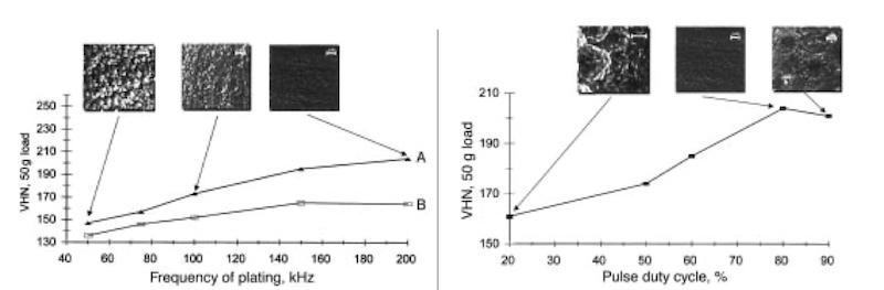 Fig. 2—Effect of pulse frequency on VHN microhardness (50g load) of copper deposits produced at 80% duty cycle and 10 A/dm2 average cathodic current density: (A) pulse reversal and (B) pulsed current plating. SEM micrographs for deposits obtained by pulse reversal plating at 50, 100, and 200 kHz are also shown. Fig. 3—Effect of pulse duty cycle on VHN microhardness (50 g load) of copper deposits produced at 200 kHz via pulse reversal plating. SEM micrographs for deposits obtained at 20, 80, and 90 % duty cycle are also shown.
Method
A glass electrochemical cell 8.5 cm in diameter and 4.5 cm in height was used in the experiments reported below. When an ultrasonic field was applied during plating, it was necessary to continuously cool the plating bath. Consequently, the bath temperature was controlled to 20 °°C by use of a water jacket connected to a circulating constant temperature bath.
The standard plating solution consisted of a CuSO4 · H2SO4 electrolyte with the concentration of the copper sulfate at 0.05 M and the sulfuric acid at 1.0 M. No brightening agents were added to the solutions, all of which were prepared from deionized water that was triply distilled and preelectrolyzed, using a copper cathode and a platinum anode at 0.2 A/dm2 overnight to further purify the solution of contaminants. This latter procedure was found to be necessary in order to obtain reproducible results.
The most common way to apply an ultrasonic field is from a source placed within the electrolyte at a location remote from the working electrode. The acoustic energy delivered to the electrode depends strongly, however, on its distance from the source and on the geometrical configuration within the electrochemical cell. These factors introduce additional variables into the interpretation of experimental data and can lead to difficulties in obtaining reproducible results. In order to eliminate these variables, we have followed the approach of Reisse et al. (16 in which the ultrasound originates at the working electrode rather than from a remote location. This involved designing a working electrode that vibrates in such a way that cavitation occurs directly at its tip. The working electrode was a 3mmdiameter copper electrode (copper 99.99% pure) mounted in the titanium probe of a sonic horn operating at the standard frequency of 20 kHz and was designed as described previously.22 By varying the amplitude of the vibration of the tip, we were able to vary the ultrasonic field strength. The counter electrode was a 2 cm diameter copper (99.99 % pure) disk mounted in an epoxy holder. Before a deposition experiment, the copper cathode tip was mechanically polished with 600-grade emery paper, then cathodically prepolarized in 0.10 M H2SO4 for several seconds at 25 A/dm2 and finally rinsed with distilled water.
The pulse plater used in this set of experiments was capable of generating a pulse width from 100 nsec to 1 msec, with rise and fall times of 10 nsec. The output of the plater supplies up to 5 A average current to the load with a peak current that can safely reach 30 A. Experiments made use of two types of galvanostatic pulse waveforms (Fig. 1): (i) pulsed current, where a cathodic square wave pulse was immediately followed by a complete current cutoff during the interval between pulses and (ii) pulse reversal current where a cathodic rectangular pulse was immediately followed by a less intense anodic square wave pulse. The range over which the experimental parameters were varied in this study is given in Table 1.
Surface quality and roughness of copper coatings were evaluated using both a scanning electron microscope (SEM) and a profilometer with a maximum resolution of 0.001 mm. The Vickers hardness with a 50g load was determined with a microhardness tester. In order for the microhardness probe not to penetrate the deposited layer to the substrate, all samples were plated with at least a 100 mm thick layer of copper.
Table 1: Range of Pulse Plating and Ultrasonic Irradiation Variables
| Parameters | Range |
| Cathodic on-time (ms); Ton;for | 0.001-100 |
| Anodic on-time (ms); Ton;back | 0-50 |
| Pulse frequency (kHz) | 0-300 |
| Cathodic peak current density (A/dm2) Ip;for | 1-25 |
| Anodic peak current density (A/dm2) Ip;back | 1-20 |
| Ultrasonic field strength (watts) | 0-125 |
| Temp (°C) | 20 |
Results and Discussion
Pulsed Current and Pulse Reversal Plating
The effect of pulse frequency on the VHN of the deposit produced by pulsed current and pulse reversal plating is shown in Fig. 2. In each case, the duty cycle and the average applied cathodic current density were held at 80 percent and 10 A/dm2, respectively. The SEM micrographs of the deposits formed after pulse reversal plating at 50, 100, and 200 kHz are also included in Fig. 2. The quality of the deposits is strongly dependent on the pulse frequency in both pulsed current and pulse reversal plating. Pulse reversal plating always produces a harder deposit than the pulsed current mode for any given frequency. As shown in Fig. 2 for pulsed current plating, the VHN value increases with pulse frequency up to approximately 150 kHz before leveling off to about 160 VHN. On the other hand, the results show that VHN values greater than 200 can be attained by using pulse reversal mode at high pulse frequencies.
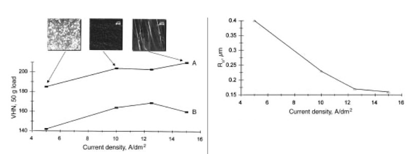 Fig. 4—Effect of average cathodic current density on VHN microhardness (50g load) of copper deposits produced at 200 kHz: (A) pulse reversal and (B) pulsed current plating. SEM micrographs for deposits obtained by pulse reversal plating at 5, 10, and 15 A/dm2 average cathodic current density are also shown. Fig. 5—Effect of average cathodic current density on the surface roughness Ru of copper deposits produced by pulse reversal plating at 200 kHz.
Comparison of the hardness values with the micrographs shows that, not surprisingly, there is a strong correlation between the surface morphology and hardness of the deposits. The smoother the deposit, the harder it is. From the experimental results shown in Fig. 2 for a duty cycle of 80 percent and an average cathodic current density of 10 A/dm2, the plated samples with the hardest and smoothest surfaces have been obtained with pulse reversal mode at 200 kHz. Because pulse reversal plating preferentially removes metal from areas that tend to overplate during the cathodic part of the cycle, this mode is able to yield greatly improved morphology over that produced by pulsed current plating. The best results reported previously for copper plating showed that coatings with VHN values above 200 (during dc or pulsed current plating) can be produced at low frequencies only if brightening agents were added.23 By using the higher frequencies in this study, we have been able to increase the hardness of copper deposits slightly beyond 200 VHN. When the frequency is increased beyond 200 kHz for both plating modes, however, it was found that only powdery and poorly adhering deposits can be formed, presumably resulting from the increasing importance of double-layer charging at the electrode/solution interface. 24
Figure 3 shows the influence of the pulse duty cycle on the VHN (50g load) at a frequency of 200 kHz for pulse reversal plated samples. The VHN value increases markedly from approximately 160 at a duty cycle of 20 percent to above 200 at 80 percent before dropping slightly with further increase to 90 percent duty cycle.
The difference between samples pulse plated at the different duty cycles is easily observed in the SEM micrographs presented in Fig. 3. The deposit formed at 80 percent duty cycle is decidedly smoother and more uniform than those produced at 20 or 90 percent. The samples plated at low duty cycles appear powdery and dull. These observations are consistent with those made by G. Devaraj et al.25 that the smoothest and hardest deposits were obtained at 80 percent duty cycles. During the on-time (or cathodic portion) of the pulse, the formation of new nuclei is favored. Moreover, the grain size and the resulting smoothness and hardness would be expected to increase at higher peak currents since it is known that the nucleation rate increases exponentially with overpotential.8 During t off-time, recrystallization may occur, and previous research 26 has shown that grain size increases with the length of the off-time.es. The most plausible explanation for the lower smoothness and microhardness below 80 percent duty cycle is that the off-time is larger than necessary to activate growth centers on the electrode surface. Small grains are thermodynamically less stable than large ones because of high surface energy, and so recrystallization into larger grains may occur during the off-time portion of a cycle. At an 80 percent duty cycle, the offtim-e is relatively short compared to that found at lower duty cycles an,d there is less time available for growth of grains that have nucleated during the on-time. Thus, finer grains are favored at such a pulse duty cycle. If the duty cycle is increased too high to 90 percent, however, the waveform begins to approach that of DC plating at extremely high current density. The process becomes mass transfer limited and the offtimes (or anodictimes) are too short for protrusions in the deposit formed during the cathodic portion to be smoothed out. The result is a porous, spongy deposit.
Figure 4 shows the effect of the average cathodic current density on the microhardness and surface morphology of electrodeposited copper produced by both pulsed current and pulse reversal plating. The SEM micrographs of the deposits formed by pulse reversal plating at 5, 10, and 15 A/dm2 are also included in Fig. 4. In the cases shown, current density has a strong effect on the microhardness and surface morphology. In the range of current densities (515 A/dm2) investigated, 10 A/dm2 has been found to be the optimum for obtaining reproducible hardness and smoothness. Interestingly, at average current densities above 10 A/dm2, the photomicrograph for the deposit formed by pulse reversal plating reveals a bladelike grain structure, although the individual grain boundaries are hard to determine.
Figure 5 provides supporting evidence for what is seen in Fig. 4. The surface roughness Ru, as measured by the profilometer, is plotted over the entire range of current densities studied for pulse reversal and shows that the surface becomes smoother as the average current density is increased. This is in agreement with the benefits of a short and intense anodic pulse discussed previously.
Table 2: Pulse Reversal Plating and Ultrasonic Irradiation Conditions for Copper Deposits From a CuSO4-H2SO4 Bath
| Parameters | Optimum Value |
| Electrolyte concentration (M): CuSO4 | 0.05 |
| Electrolyte concentration (M): H2SO4 | 1.0 |
| Cathodic on-time (msec); Ton;for | 0.004 |
| Anodic on-time (msec); Ton;back | 0.001 |
| Pulse frequency (kHz) | 200 |
| Cathodic peak current density (A/dm2) Ip;for | 22 |
| Anodic peak current density (A/dm2) Ip;back | 18 |
| Ultrasonic field strength (watts) | 60 |
| Temperature (°C) | 20 |
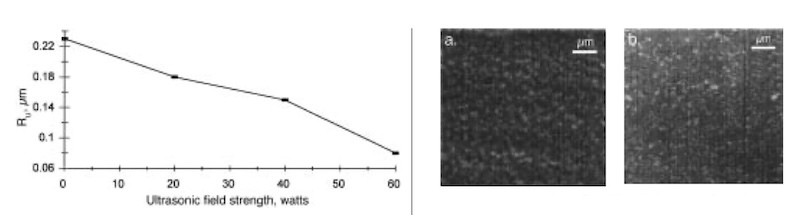 Fig. 6—Effect of ultrasonic field strength on surface roughness Ru of copper deposits produced by combined ultrasonic irradiation and pulse reversal plating at 200 kHz, 80% duty cycle, and 10 A/dm2 average cathodic current density. Fig. 7—SEM micrographs at 200 kHz, 80% duty cycle, and 10 A/dm2 average cathodic current density: (A) copper deposit produced by pulse reversal plating in the absence of an ultrasonic field; (B) copper deposit produced by combined ultrasonic irradiation at 60 watts field strength and pulse reversal plating.
Effect of Ultrasonication
The smoothest and hardest deposits obtained during this study have been produced by applying an ultrasonic field during pulse reversal plating. The effect of ultrasonic field strength on surface roughness for pulse reversal at 200 kHz, 80 percent duty cycle, and 10 A/dm2 average cathodic current density is shown in Fig. 6. The surface roughness decreases continuously from approximately 0.23 to 0.08 m as the ultrasonic field strength is increased from 0 to 60 watts. The deposit obtained at 60 watts field strength is the smoothest obtained during this study. This deposit also has the highest measured microhardness value (230 VHN at 50 g load). The remarkable leveling effect is demonstrated by the fact that a near mirror-smooth surface is produced without having to do any mechanical polishing, even though the surface prior to plating was polished only with 600-grade emery paper. The SEM images clearly show a compact grain structure with individual grains smaller than those shown before when ultrasound is not used (Fig. 7). Grain sizes appear to be on the order of 0.5 m. If the ultrasonic field strength is raised above 60 watts, however, plating produces a rougher deposit because of pitting of the surface caused by the presence of a stronger field. Table 2 summarizes the pulse reversal plating and ultrasonic conditions found in this study to produce the smoothest and hardest deposits.
Most of the above effects can be ascribed to cavitation, which involves the formation and sudden collapse of bubbles within a liquid medium exposed to an ultrasonic field. Depending on the position of the bubbles with respect to a solid surface, two modes of cavitation are known. If a cavitation bubble is far from a surface, then it implodes symmetrically. If it is near or at a solid surface during its collapse phase, the solid surface exerts a drag force on the portion of the void nearest the surface. This asymmetry leads to a net inward force in the form of a liquid jet oriented toward the surface. The latter mode of cavitation produces intense mixing at the cathode surface and significantly improves mass transfer. Another possible effect, which may only be significant during pulse plating, is the interaction (destructive or constructive) between the oscillation of the diffusion layer resulting from the pulsing of the current and the oscillation of the diffusion layer induced by ultrasound. Very little research on such an interaction has been done, however, so it is not well understood. More work in this area is warranted.
Conclusions
The influence of current pulsing and an ultrasonic field on the morphology and microhardness of copper deposits plated onto copper cathodes from a sulfate bath without the addition of brightening agents has been investigated. Higher pulse frequencies and peak current densities were applied than have been previously reported for copper plating. Pulse reversal plating is always found to produce a smoother and harder deposit than pulsed current plating. Comparison of SEM images with profilometer and microhardness measurements has shown that the smoother the deposit, the harder it becomes. By applying pulse reversal plating at 200 kHz, 80 percent duty cycle, and 10 A/dm2 average cathodic current density, we have been able to produce coatings with VHN microhardness (50 g load) slightly above 200, heretofore achievable only with the addition of brightening agents. Even better results of 230 VHN microhardness have been obtained, however, by applying an ultrasonic field strength of 60 watts in combination with the pulse reversal conditions described above. Moreover, the deposits have a mirror-smooth finish without any mechanical polishing being required. This has the practical advantage of producing not only extremely hard and smooth surfaces, but also may lessen the influence that the initial state and history of the substrate have on the final deposit that is formed. This may ease the requirements of the pretreatment steps prior to plating.
About the Authors
Peter Kristof is a doctoral student in the Department of Chemical Engineering at the University of Waterloo. He holds a BSc in chemistry from the University of Guelph in Canada and an MASc in chemical engineering from the University of Waterloo. He has been working with Dr. Pritzker since 1992 and is experienced in such areas as electrodeposition and electroplating, biochemistry, experimental design, and statistical analysis. Dr. Mark Pritzker is an associate professor in the Department of Chemical Engineering at the University of Waterloo, Waterloo, Ontario, Canada N2L 3G1. His research interests include electrodeposition and electroplating, electropolymerization, hydrometallurgy, modeling of electrochemical and metallurgical processes, and wastewater treatment.
Acknowledgments: This project was supported financially by the Natural Sciences and Engineering Research Council of Canada (NSERC). The authors are also grateful to Professor M. Yovanovich, Department of Mechanical Engineering, University of Waterloo, for use of the microhardness tester and to Professor J. Medley, Department of Mechanical Engineering, University of Waterloo, for use of the profilometer.
References
1. S. Coughlan, Trans. Inst. Met. Fin., 73(2), 54 (1995).
2. K.I. Popov, M.G. Pavlovic, L.J. Pavlovic, M.I. Cekerevac & C.Z. Removic, Surf. Coat. Technol., 34(3), 355 (1988).
3. S. Roy & D. Landolt, J. Appl. Electrochem., 27(3), 299 (1997).
4. R.D. Grimm & D. Landolt, Surf. Coat. Technol., 31(2),151 (1987).
5. P. Leisner, Thesis: PI 92.24-A. AP92.39, The Technical University of Denmark (1992).
6. A.R. Despic & K.I. Popov, J. Appl. Electrochem., 1(4), 275 (1971).
7. N. Ibl, Surf. Technol., 10(2), 81 (1980).
8. A. Damjanovic & J. O’M. Bockris, J. Electrochem. Soc., 110(10), 1035 (1963).
9. G. Holmbom & B.E. Jacobsson, Surf. Coat. Technol., 35(3-4), 333 (1988).
10. W.R. Wolfe, H. Chessin, E. Yeager & F. Hovorka, J. Electrochem. Soc., 101, 590 (1954).
11. S.R. Rich, Plating, 42, 1407 (1955).
12. T.Y. Wei, Y.Y. Wang & C.C. Wan, Plat. and Surf. Fin., 66, 47 (March 1979).
13. Y. Zhao, C. Bao, R. Feng & Z. Chen, Ultrason. Sonochem., 2(2), S99 (1995).
14. C.T. Walker & R. Walker, J. Electrochem. Soc., 124(5), 661 (1977).
15. M.C. Hsiao & C.C. Wan, Plat. and Surf. Fin., 76, 46 (March 1989).
16. J. Reisse, H. François, J. Vandercammen, O. Fabre, A. Kirsch-De Mesmaeker, C. Maerschalk & J.-L. Delplancke, Electrochim. Acta, 39(1), 37 (1994).
17. R. Walker & N.S. Holt, Plat. and Surf. Fin., 67, 92 (May 1980).
18. R. Walker & C.J. Perrins, Plat. and Surf. Fin., 71, 77 (Oct. 1984).
19. R. Walker & S.A. Halagan, Plat. and Surf Fin., 72, 68 (April 1985).
20. R. Walker, Chem. Br., 26(3), 251 (1990).
21. T.J. Mason, J.P. Lorimer & D.J. Walton, Ultrasonics, 28(5), 333 (1990).
22. R.G. Compton, J.C. Eklund & D.N. Waller, Electrochim. Acta, 41(2), 315 (1996).
23. D.S. Stoychev & M.S. Aroyo, Proc. 83rd AESF Annual Technical Conf., (SUR/FIN ’96), pp. 851 - 858, Cleveland, OH (1996).
24. C.C. Segal, A.B. Chase & A.M. Young, J. Electrochem. Soc., 139(6), 1580 (1992).
25. G. Devaraj & S.K. Seshadri, Plat. and Surf. Fin., 79, 72 (Aug. 1992).
26. Y. Qi-Xia, Plat. and Surf Fin., 76, 53 (Aug. 1989).