


Back in the 1930s, I doubt Dr. Richard O. Hull, when applying for a patent for his test plating cell, ever dreamed this unique tool would become the main service tool in the decorative plating industry today.
 Ralph DixonMost decorative plating additives in the world would be developed using his Hull cell (Fig. 1). The cell would also be the main service tool for controlling decorative plating processes, especially copper, nickel, and chromium. With a little imagination, one can custom-shape panels to simulate almost any situation a plater may face (Fig. 2). These can vary from panels with shelves to pick up roughness and pitting, tight “V” shapes to plate very low current density areas checking for metallics, saw pattern-sided panels to check for fine nodulations in high current densities, and perforated panels simulating low current density areas throughout the panel. Hull cells can stand in for a chemical analysis when an analysis is not available.
Working with Hull cells breaks down into two categories: (1) properly plating panels and (2) properly interpreting panels. You will find very few photographs of plated panels showing the many conditions achieved, simply because it is virtually impossible to photograph a panel with its highly reflective surface. Hazes, clouds, and speckling do not photograph. Most information on panels relies on drawings to depict conditions. I have always recommended building a library of panels tuned to your operation. After plating your normal test panels, and before discarding the test solution, plate additional panels from solutions deliberately contaminated with the possible contaminants in the line. This will allow you to display conditions for future reference and training. Because the plated surface is very active and subject to oxidation, store these panels in Ziploc plastic bags.
Note: this article was written in 2009
Equipment
Hull cells are available in two sizes, 267 mL and 1,000 mL. In decorative plating, the 267mL size is recommended. The 1,000mL cells are required in baths using very high current densities, such as acid copper plating on grounding rods, which use current densities up to 600 A/ft². The larger volume is required to compensate for temperature increases and current-carrying capacities. Hanging cells are also available, which extend down into the actual plating tank.
Table 1: Panel amperage (267mL Hull cell panel)
| Amperage; A | Current density range; A/ft2 |
| 1.0 | 0.5 - 40.0 |
| 2.0 | 1.0 - 80.0 |
| 3.0 | 1.5 - 120.0 |
| 5.0 | 2.5 - 200.0 |
Hull Cell
The 267mL cell was designed to plate a deposit on a steel or brass panel over a selected current density range. As shown in Fig. 1, the cathode panel is placed at an angle with respect to the anode face. Thus, the local current density is highest at the end closest to the anode, while conditions at the other end are at a low current density. Table 1 shows the current density ranges produced at various applied currents.
Electrodeposition is based on average current density values. When plating at an average of 40 A/ft², we also observe what the deposit looks like at 2.0 A/ft² and 80 A/ft². Since plating problems usually start in the low current density areas and work up as well into higher current density areas (as well as in the other direction), we can see problems before they are in the current density range in which we are plating on the part — sort of a “soothsayer” of plating conditions.
We selected the 267mL volume to simplify calculations. Adding 2.0 g to the cell equals 1.0 oz/gal in the bath. One milliliter in the cell equals 3 pints/100 gal in the bath. The advantage of the Hull cell is that you can work by trial and error until you establish the correct addition, consuming only a small volume of the bath. You can add brightener this way, choose the best results, and then add that volume to a fresh bath. It is recommended that no more than three panels be plated per test volume, as bath conditions change quickly in that small volume of solution.
Hull Cell Rule
A graphic representation of the current density ranges shown in Table 1 is available in the form of a handy Hull cell rule (Fig. 3). By placing the panel on a Hull cell rule, one can observe the current density range of interest.
The Hull cell rule allows you to view current density ranges for 1.0 to 5.0 A panels (as tabulated in Table 1). It also contains formulas to calculate additions, as well as a millimeter rule to measure chromium coverage.
Hull Cells Available for Different Applications
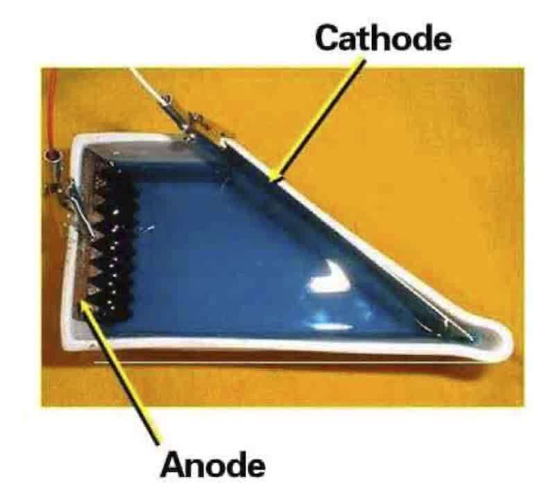 Figure 1—Overhead view of the Hull cell configuration.Because of the different chemical environments involved in the various decorative plating baths, several cells are available specific to the application (e.g., copper, nickel, chromium, etc.):
- Standard nonheated, non-air-agitated Lucite Hull cell, recommended for cyanide zinc and cadmium solutions.
- High-density polyethylene Hull cell, recommended for chromium solutions
- Nonheated, air-agitated Hull cell for baths requiring agitation, recommended for acid copper and chloride zinc.
- Heated and air-agitated Hull cell, recommended for semi-bright and bright nickel solutions.
Power Supplies
Rectifiers should provide at least 10 A DC at 12 V, with a maximum ripple of 5%. You can process multiple Hull cells with one rectifier by connecting them in series.
Agitation
A Hull cell may be air-agitated with a standard aquarium air supply and a needle-valve control. Paddle agitation is also available for non-air-agitated baths, such as cyanide copper.
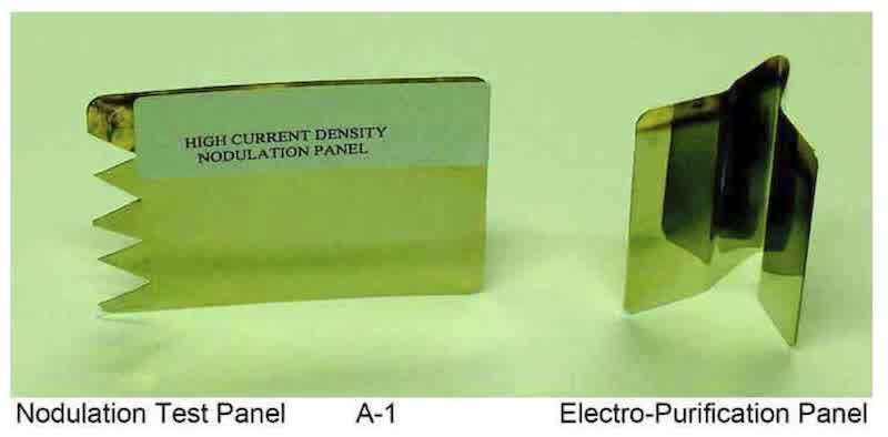
Figure 2—Examples of specialized Hull cell test panels.
Panels
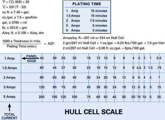 Figure 3—Hull Cell rule.Panels are available in both brass and steel. Brass panels have a strippable coating that is peeled off before cleaning. This coating is easy to remove on new panels. However, as panels age, this film becomes quite difficult to remove. It is important to maintain a supply of fresh panels. Panels are lustrous with very fine vertical polishing lines. Panels should be examined prior to use to be sure there are no surface imperfections or pitting.
Steel panels have a thin electroplated zinc deposit on them, which is stripped in hydrochloric acid prior to use. Care must be taken that a clean acid is used, as zinc builds up, and panels will develop a smut that must be physically removed. I prefer brass panels over steel for nickel. Polished brass mirrors back the nickel deposit.
Cleaning of Panels
Producing a good panel requires good cleaning. Panels should be cathodically cleaned. This is accomplished in a 2,000mL stainless steel beaker. A hot plate sized to maintain a temperature of 180°F is recommended.
- Cathodically clean for 2.0 min at 5.0 to 8.0 A.
- Cold water rinse.
- Acid dip in 10% hydrochloric acid.
- Cold water rinse
Panels should be placed immediately in the cell and plated.
Additive Additions
The recommended concentration of many additives may be as small as 0.1 vol%. Because of the relative scale of a Hull cell test, it is difficult to pipette an addition that small. Diluting additives to 10% allows you to make a 1 mL addition, which is more precise.
Process Analysis - Bright Nickel
A standard panel for bright nickel is plated for 10 min with moderate air agitation at 2.0 A. The panel should be bright over the complete range, exhibit good leveling, with a slight swirl in the low current density area. The panel should be free of speckling, have good ductility, and adequate coverage on the back. Leveling is determined by the degree of visible polishing lines. In a well-balanced bath, virtually no lines will be visible except for the last 3/16” of the panel (lowest current densities). When the panel is bent 180°, cracking should not be heard.
Common Nickel Problems
1. Dullness: Dullness usually arises from low secondary brightener. The Hull cell panel lacks overall brightness, especially at low current densities. Panel polishing lines are visible. The panel may also display a bluish cloud. To correct this, make a 10% solution of the secondary additive. Add 1.0 mL in each subsequent Hull cell test until a bright deposit is achieved.
2. Roughness: Roughness may not be apparent on the vertical surface of the panel. It is necessary to cut and form a shelf panel, where a horizontal surface is created. This will allow particulate matter to settle on the “shelf,” replicating the condition where roughness can occur. To correct, filter the solution through a Buchner Funnel and Whatman #42 filter paper. Rerun the panel to ensure the problem is solved.
3. Stardusting: Stardusting is caused by micron-sized particles from breakdown products. To correct, obtain a solution sample volume large enough to produce two samples (267 mL × 2 = 534 mL minimum). Plate a 30 min / 2.0 A panel. If stardusting is visible, to the second sample, add 1.0 mL of a dispersant wetting agent. Plate the second Hull cell panel. If free of all stardusting, make an equivalent addition to the bath.
4. Pitting: Pitting is caused by organic contamination. To correct, 0.2 vol% of wetting agent should be added to the sample bath. Run a second Hull cell panel. If pitting is still present, the solution is filtered through a Buchner funnel with #42 Whatman filter paper coated with activated carbon. A third panel is run and inspected.
5. Metallic Impurities: Metallic contaminants start as black bands in the low current density areas. Zinc will appear as zebra stripes. To correct, a V-shaped panel is formed which fits into the low current density area of the cell. A panel is plated at 0.2 A for 10 min and examined. A time sequence may be calculated using this panel to determine the electropurification time needed to remove the metallic contaminants.
Process Analysis - Decorative Hexavalent Chromium - Fluoride/Sulfate Bath
Chromium baths may be totally controlled with a Hull cell with a little practice and learning how to interpret the panels. Care must be taken on handling the electrical contacts. Any loss of current will cause a white wash pattern, leaving you to wonder if the problem is chemical or poor contact. Chromium should be plated over a freshly plated nickel panel, preferably over the nickel being used in the plating line. I prefer to nickel plate my panel, rinse well, and place it in the cell, make electrical contact, then pour the chromium into the cell at 1.0 A, gradually increasing the current to 5.0 A for 2.0 min. This procedure simulates the automatic programming used on most automatic plating machines. Coverage across the panel will vary from 60 to 85 mm for the average bath. The coverage range corresponds to 75 to 30 A/ft2, as per the Hull cell rule shown in Fig. 3. The goal is to extend the coverage as much as possible, i.e., to the lowest possible current density. The deposit should be free of white wash and rainbow staining. The normal panel is rinsed and wiped dry. To check for staining, the panel may be air-dried.
Common Chromium Problems
1. High current density burn: High current density burn is related to either low sulfate or a high chromic acid-to-sulfuric acid ratio. To correct, a series of tests with additions of sulfuric acid is performed.
2. Poor coverage: Poor coverage is related to either high sulfate or a low chromic acid-to-sulfuric acid ratio. To correct, a series of tests with additions of barium carbonate (to lower sulfate) is performed.
3. Whitewash: Whitewash is connected with low fluoride. To correct this, a series of tests with additions of the fluoride catalyst is performed.
4. Rainbow stain: Rainbow staining is also related to low fluoride. As with white wash, a series of tests with additions of the fluoride catalyst is performed to determine corrective action.
5. High current density halo: A high current density halo is related to high fluoride. A series of tests with additions of boric acid (reducing fluoride) is performed to determine corrective action.
Process Analysis - Acid Copper
Acid copper Hull cell panels are quite representative of the plating bath. That is, additions to the cell accurately reflect the results of the work in the bath. An air-agitated cell is used with vigorous agitation. Panels from a bath in balance are bright from high to low current densities. Acid copper baths level well, and this is demonstrated on the polished brass panel. Panels are plated at 2.0 A for 10 min.
Common Copper Problems
1. Low copper sulfate: Low copper sulfate in solution produces a high current density burn in the Hull cell panel. Incremental additions of copper sulfate in the test solution will determine what should be added to the tank. However, see (2) below.
2. Low sulfuric acid – High current density burn: Low sulfuric acid in solution also produces a high current density burn in the Hull cell panel. Incremental adds of sulfuric acid in the test solution will determine what should be added to the tank. Since both low copper sulfate and sulfuric acid induce the same effect, the Hull cell tests should be done in tandem, i.e., one test with an increment of copper sulfate added to the original solution, and a second test with an increment of sulfuric acid added to another sample of the original solution. Whichever of the two is more effective in reducing the high current density burn can help to weed out the culprit.
3. Low carrier additive: Low carrier additive in solution results in cloudiness in the mid to high current density areas of the Hull cell panels. Further, nodulation can appear on the panel edges. To correct, 1.0 mL of the carrier additive should be added to the 267mL test volume, with the Hull cell result evaluated to see if more is required.
4. High carrier additive: High carrier additive produces a cloudy deposit with low current density skip plate. Before running the Hull cell test, the solution is filtered through a Buchner funnel with #42 Whatman filter paper coated with activated carbon to reduce the additive.
5. Low secondary additive: Low carrier additive in solution results in dullness in the low current density areas of the panels. 0.2 vol% of the secondary additive should be added in the initial corrective Hull cell test..
6. High secondary additive: High secondary additive in solution produces “worm tracks” throughout the panel. The test solution is filtered through a Buchner funnel with #42 Whatman filter paper coated with activated carbon to reduce the additive.
Summary
The Hull cell is a very diverse tool with unlimited possibilities in the control of electroplating baths. Use your imagination in designing panels to exhibit particular plating problems. Assemble a library of panels for future reference and training. We have discussed decorative applications only. The Hull cell will help you solve problems in any electrolyte that will deposit metal. As long as there is plating, there will be Hull cells.
The various test conditions for Hull cell testing of the various solutions used in decorative plating are summarized in Table 2.
Table 2: Summary of Hull cell test conditions for decorative plating processes
| Electrolyte | Cell | Agitation | Temperature | Current | Time | Panel |
| Cyanide Copper | L | Mech. | 160 °F | 5.0 A | 5 min | Brass |
| Acid Copper | L | Air | 75 °F | 2.0 A | 10 min | Brass |
| Semi-bright Ni | L | Air | 145 °F | 2.0 A | 10 min | Brass |
| Microporous Ni | L | Air | 145 °F | 1.0 A | 3 min | Brass |
| Bright Ni - R | L | Air | 145 °F | 2.0 A | 10 min | Brass |
| Bright Ni - B | L | Air | 145 °F | 1.0 A | 5 min | Brass |
| Chromium | HPE | None | 110 °F | 5.0 A | 2 min | Ni/Brass |
L - Lucite; HPE - High density polyethylene
Ralph Dixon has been serving the metal finishing industry for the past 50 years in all phases, from technical field service to sales management with world-class suppliers. He specializes in decorative nickel and chromium finishes to the appliance, automotive and motorcycle industries. He is currently involved as a consultant in the promotion of decorative plating processes in the United States and South America with Basically Nickel Inc. Note: This article was written in 2009.