Abrasion resistance of anodized aluminum is an important property that is often required for material performance and quality control.
 Alan JaeneckeSince its release in 1953, MIL-A-8625 - Anodic Coatings for Aluminum and Aluminum Alloys has been the primary anodizing specification used in the United States with section 4.5.5 specifying how to quantify the abrasion resistance of electrolytically formed hard anodic oxidation coatings. Referred to as the “Taber Test,” results have been used for acceptance testing, process control, comparative ranking or to correlate with end-use performance.
For components that require a wear resistant surface, the MIL specification requires a maximum Taber wear index value of 1.5mg/1000 cycles for type III hard coated aluminum surfaces or 3.5mg/1000 cycles for alloys with >2% Cu. Examples of applications include pistons, cylinders, hydraulic gear, valves, sliding parts, hinge mechanisms, cams, gears, swivel joints, insulation plates, blast shields, etc.
Despite the maturity of the method, Taber Industries personnel saw an increase in questions from anodizers in the mid-2000’s looking for clarification on how to perform the abrasion test. After a review of the procedure, Taber identified a number of opportunities for improvement. Efforts to update the document were not successful; however, in 2012 a presentation to ASTM’s B08 committee on Metallic and Inorganic Coatings was made to develop a detailed test procedure for abrasion resistance of anodized aluminum.
Taking advantage of ASTM’s Collaboration Area, key industry personal were asked to participate in the creation of this new ASTM method.
The first step of this project was to perform a comprehensive review of existing Taber test methods intended for anodized aluminum. Procedural requirements were compared, and industry comments requested for any significant differences. Taking advantage of ASTM’s Collaboration Area, key industry personal were asked to participate in the creation of this new ASTM method. By September 2018, a draft method was ready for peer review and a new work item registered with ASTM.
In November 2020, MIL-A-8625F was revised to MIL-PRF-8625F, which, according to an article1 in www.FinishingAndCoating.com written by Chemeon's Westre, PhD and Catherine Munson, PhD, “serves to bring a very useful, but dated, specification into the 21st century.” The updates did not change how anodizing is performed or the performance requirements, but there are modifications that anodizers need to be aware of.
This article presents a historic review with some of the issues concerning the MIL-PRF-8625F abrasion test that still need to be addressed and how the September 2022 publication of ASTM B1023 – Standard Test Method for Abrasion Resistance of Hard Anodic Coatings by a Taber-Type Abraser2 will help.
Overview of Abrasion Test Referenced in MIL-PRF-8625F
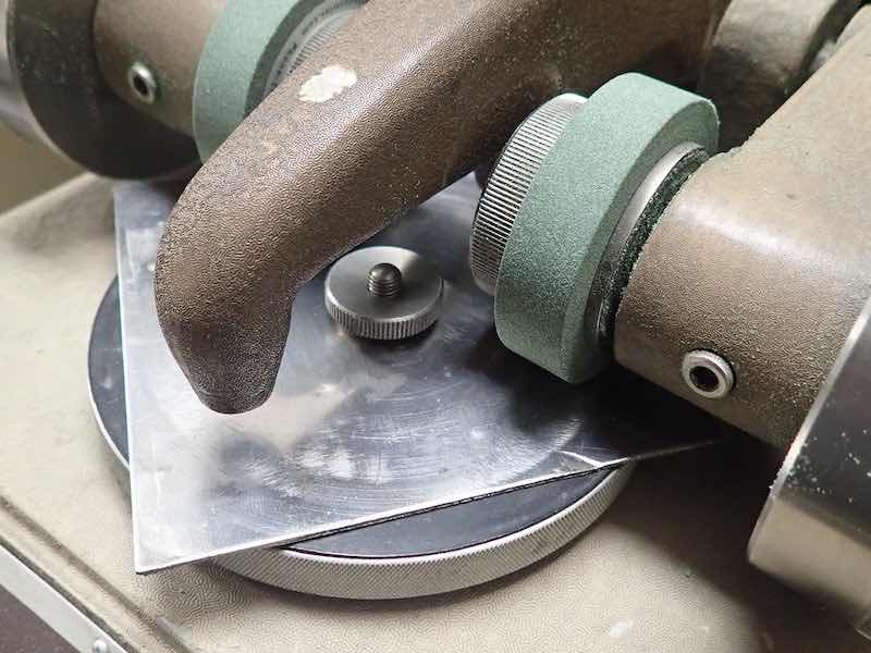
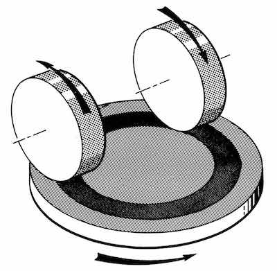 The test uses a Taber abraser, which generates a combination of rolling and rubbing to cause wear to the specimen surface. A flat test coupon, approximately 100mm square with a center hole, is mounted to a turntable platform that rotates on a vertical axis at a fixed speed. Before each test, two Taber CS-17 abrading wheels are refaced with an S-11 disc to standardize the wheel surfaces. The abrasive wheels are lowered onto the specimen surface with a load that applies a pressure of 1000 gram per wheel.
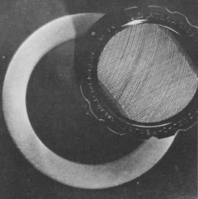
The characteristic rub-wear action is produced by contact of the test specimen against the sliding rotation of the two abrading wheels. As the turntable rotates, the wheels are driven by the test coupon in opposite directions about a horizontal axis displaced tangentially from the axis of the specimen while a vacuum system removes loose debris during the test. The resulting abrasion marks form a pattern of crossed arcs in a circular band that cover an area approximately 30 cm2. Wear is quantified as cumulative mass loss or loss in mass per thousand cycles of abrasion (Taber wear index) where the lower the wear index, the better the abrasion resistance quality of the material.
 The resistance to abrasion, as measured on a testing machine in the laboratory, is generally only one of several factors contributing to wear performance as experienced in the actual use of the material. Other factors may need to be considered in any calculation of predicted life from specific abrasion data. The resistance of hard anodic coatings to abrasion may be affected by factors including test conditions, type of abradant, pressure between the specimen and abradant, composition of the alloy, thickness of the coating, and the conditions of anodizing or sealing or both.
Do Specimens Need Conditioning Prior to Testing?
The original MIL-A-8625 specification stated, “Test specimens shall be tested in accordance with Method 6192.1 of FED-STD-141”. Unfortunately, Federal Standard 141 was cancelled on March 22, 2001 and ASTM D4060 - Standard Test Method for Abrasion Resistance of Organic Coatings by the Taber Abraser was listed as the replacement. The 2020 release of MIL-PRF-8625F officially replaced the reference to Fed-STD-141 Method 6191.1 with ASTM D4060.
Both method 6192.1 of FED-STD-141 and ASTM D4060 required specimens to be conditioned unless otherwise agreed. When following ASTM D4060, the coated panels are to be conditioned for at least 24 h at 23 °C ± 2 °C and 50 % ± 5% RH. In contrast, ISO 10074 (annex B); Specification for hard anodic oxidation coatings on aluminum and its alloys and BS 5599; Specification for hard anodic oxidation coatings on aluminium and its alloys for engineering purposes both state “to allow at least 1 day to elapse between hard anodizing and abrasion testing. During the period, store the test pieces in the test environment.”
To address the question of conditioning, a recommendation was submitted to NAVAIR in September 2022 to revise MIL-PRF-8625F.
During the development of ASTM B1023, a study was conducted to determine the influence of environmental conditions on anodized aluminum abrasion tests. Lab participants were asked to weigh each specimen ‘as received’, then condition the specimens for a minimum of 24 hours in the test environment. Ten labs participated in the study and four did not use environmental controls. Due to the time of year the tests were conducted, humidity levels for these four labs averaged less than 40% and the specimens showed a decrease in mass after conditioning for 24 hours. Taber also collected data that revealed the friction between the abrasive wheels and specimen during testing caused an increase in specimen temperature. From this information, it was decided a tightly controlled environment was not required and ASTM B1023 was written such that specimens are conditioning for a minimum of 24 hours at 23 °C ± 5 °C and no greater than 60 % relative humidity. B1023 also permits placing specimens in a desiccator prior to and following the test.
To address the question of conditioning, a recommendation was submitted to NAVAIR in September 2022 to revise MIL-PRF-8625F such that it replaces the reference of ASTM D4060 with ASTM B1023.
How Often Should Abrasive Wheels be Refaced?
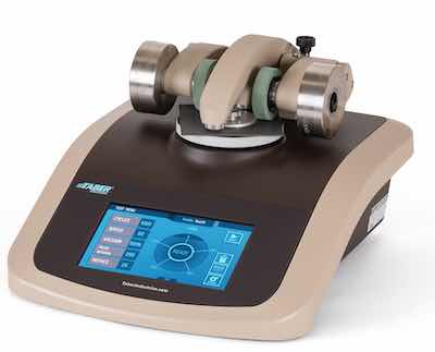 Taber Model 1700When performing the Taber test, the abrasive wheels may become clogged depending on the adhesive character of material worn off the specimen. This could change the abrasive characteristics of the wheels and have a significant impact on the test results. To reduce this variation, Taber recommends the wheels be resurfaced prior to each test. This ensures the abrasive wheels are standardized and any debris still adhered to the wheel surface from previous tests is removed.
ASTM D4060 was written for organic paints and coatings, which is one material that had a tendency for the wheel surfaces to ‘clog’ with wear debris during the test. To rectify this, ASTM D4060 was modified in 2001 requiring the wheels to be refaced before testing and after every 500 cycles. Although the MIL-A-8625 procedure states to “reface once during the 10,000 cycle test”, NADCAP auditors quickly discovered this discrepancy. What they did not realize is that following the prescribed refacing as defined in ASTM D4060 added significant cost to the test, and had a tendency of increasing the mass loss of the specimen. This problem was corrected in 2019 when ASTM D4060 was updated with the following note: “Inorganic coatings do not require the abrasive wheels to be resurfaced after every 500 test cycles”.
One other cause of confusion was that MIL-PRF-8625 does not clarify when to reface the wheels. Part of Taber’s submission to NAVAIR was to replace the statement in MIL-PRF-8625F from “at least once every 10,000 cycles” to “the abrasion wheels shall be refaced prior to each test.” One other item to note, ASTM D4060 specified a refacing of either 25 or 50 cycles. ASTM B1023 specifies refacing for 50 cycles.
What Should the Settings be for the Vacuum and Nozzle?
Method 6192.1 of FED-STD-141 originally specified a vacuum nozzle height of 1/32” above the test film with the vacuum suction level being approximately 50 points on the dial or increased to 90. In the 2001 release of ASTM D4060, the vacuum nozzle gap was defined as a distance of 4 mm (1/4”) above the test film. Because the conversion between metric and English units were not equivalent, this value was changed in 2007 to 6.5 mm (1/4”) and operators were instructed to set the vacuum suction force to 100, which could be decreased if agreed upon by the interested parties. In the 2014 version of ASTM D4060, the English units were removed and the vacuum nozzle was changed to a distance of 3 ± 1 mm. This is the same vacuum nozzle gap specified in ASTM B1023.
During the development of ASTM B1023, a concern arose that a vacuum nozzle gap requirement that was extremely small may create issues. For example, ISO 10074 (annex B) specifies a vacuum nozzle height “within 0.8 to 1.5 mm of the test piece”. The objective is to ensure the vacuum nozzle gap effectively removes the wear debris and permits ample airflow.
Should You Wait To Take The Final Mass Loss Measurement?
During the development of ASTM B1023, a study was conducted to investigate if, after testing, freshly exposed anodic coatings gained mass by absorbing water vapor. Based on a study conducted by H.G. Arlt in 1940, Wright Air Development Center released a technical report in 1953 stating, “There is a general decrease in the abrasion resistance of all the alloys with increase in the time of exposure to both the atmospheric conditions and humidity. The decrease is greater under the high humidity conditions than it is under exposure to atmospheric conditions and in most cases is proportional to the thickness of the coating.”3 A 1979 article in Plating and Surface Finishing further supported this claim with the statement “Seasonal fluctuations occur if abrasion-resistance testing (using the Taber Abraser Test) of hard anodized aluminum is performed without humidity control.”4 ISO 8251 – Anodizing of aluminium and its alloys - Measurement of abrasion resistance of anodic oxidation coatings also makes the claim that “Freshly exposed anodic oxidation coatings can gain in mass by absorbing water vapour.”
To investigate this, labs were asked to measure mass immediately following the 10,000 cycle abrasion test and after leaving the specimen in the test environment for 1 hour after. After reviewing the data, the decision was made to include the following note in ASTM B1023: “It has been observed that freshly exposed anodic oxidation coatings can gain mass by absorbing water vapor. Hence, tests may be subject to errors depending upon variations in atmospheric humidity or if there is any significant delay with measuring mass after testing is completed. To reduce this variation, specimens may be placed in a desiccator or conditioned in the test environment for a minimum of 1 h or as agreed upon by the interested parties prior to measuring specimen mass after abrasion.”
What Speed Does the Taber Abraser Turntable Rotate?
The original Taber Abrasers from the 1930’s and 1940’s included a specimen holder that rotated at a speed of 70 rpm. When Taber changed from Model J to Model 174, the specimen holder speed changed from 70 to 72 rpm. It is important to mention that a step-up transformer was used with the early Taber abrasers to accommodate 230V/50Hz power supply, which caused the specimen holder to rotate at 60 rpm. One or both of these speeds are referenced in most Taber test methods and are available as the standard operating speeds. Unfortunately, an error exists in MIL-PRF-8625F that specifies “the wheels shall revolve on the anodic coating at a speed of 70 revolutions per minute (RPM)”. A recommendation was submitted to NAVAIR in September 2022 to revise MIL-PRF-8625F and eliminate the speed reference.
How Can the Specimen Influence Test Results?
There are a number of factors to monitor to ensure good test data, including the condition of the test specimens. “A test panel coated and submitted for testing can cause considerable differences in results.”5 First, to generate a uniform wear pattern specimen surfaces must be plane and parallel. Second, if the panel thickness is not sufficient, stressed anodic coating may cause the panel to bow. If a test specimen is slightly bowed or warped and either side can be tested, mount the specimen to the turntable platform with the concave side facing down. The pressure applied by the clamp plate and nut may be sufficient to eliminate the bow. If this situation cannot be corrected, uneven wear may result and the specimen should be discarded. The minimum nominal specimen thickness listed in ASTM B1023 is 1.6 mm, which matches MIL-PRF08625F and AMS 2469 - Hard Anodic Coating Treatment of Aluminum and Aluminum Alloys – Processing and Performance Requirements. Third, the process of drilling or punching the center hole may result in the formation of a small burr that must be removed prior to mounting the specimen. If the hole was drilled or punched prior to the anodizing process, an anodic build up may interfere with mounting the specimen. If the panel does not easily fit over the threaded screw on the specimen turntable platform, forcing (or screwing) the panel on may break loose any built up anodic material. If this happens, the specimen should be weighed again prior to starting the test. Fourth, specimens should be free of all foreign substances, oxides and soils, such as greases, oil, paint, and welding flux. Before anodizing, use proper cleaning procedures to remove oxide and other interfering films. During all pretreatments, anodizing, and post treatments, specimens should be handled by their edges to avoid contamination or mechanical damage.
How Can the Anodizing Process Influence Test Results?
The properties and characteristics of hard anodic oxidation coatings can be significantly affected by both the alloy and the method of production. Things to watch for include pretreatment, electrolyte bath temperature, bath agitation, current density, bath chemistry, time in solution, and processing differences (tanks, racking, specimen distance from cathodes, etc.).
While corrosion resistance is often increased by sealing the coating, it has been observed that sealing or dyeing can reduce the resistance to abrasion by over 50%.
Hard anodizing will usually result in a dimensional increase on each surface equal to about 50% of the coating thickness. The thickness of anodized coatings often ranges between 8 μm to 150 μm; however, the normal thickness for wear applications tends to be 40 μm to 60 μm. The outer surface of the anodic coating may be softer or less dense which may cause a greater mass loss during the first 1,000 abrasion cycles than the remaining cycles. “The anodic coating has the well-known micro-cellular structure of fine pores and its density can change through the thickness, the surface layer more porous and softer than the inner layer.”6 Two similar procedures are described in ASTM B1023, but method B does not report the first 1,000 abrasion cycles. If there is a concern of surface variation, method B may provide a more representative value for the bulk coating.
The resistance to abrasion is generally measured on unsealed anodic oxidation coatings. While corrosion resistance is often increased by sealing the coating, it has been observed that sealing or dyeing can reduce the resistance to abrasion by over 50%.
How Does Instrument Calibration Influence Test Results?
Despite the appearance of being a simplistic test, the Taber abraser involves a complex interaction of each critical component. An out of tolerance condition of one element can lead to significant differences in test results.
Improper alignment of the abrasive wheels will lead to each wheel abrading a different path from its complementary wheel across the specimen as well as the wheels on other machines. As an example, the impact of a 4 mm abraser arm misalignment would reduce wheel overlap from 100% to approximately 65%. This increases the total wear area by approximately 1000 sq. mm; however, the misalignment would result in a less aggressive test because the area abraded by both wheels has been reduced.
Wheel bearing rotation plays a critical role in the proper operation of the Taber abraser. Worn wheel bearings may have excessive play or inhibit easy wheel rotation. Specific areas to examine for bearing wear are the pivot areas of the abrader arm and the shaft on which the wheel revolves. This includes but is not limited to any sideways, twisting, or other motion outside the specific rotation of the arm or the shaft. A “stuck” wheel bearing generates sliding wear vs. the intended “rub-wear” action of a rolling wheel.
Table runout issues, typically noticed as a table wobble, can result in improper wear as the wheel contact area changes during the table rotation.
A properly working Taber vacuum system (including proper vacuum nozzle height and vacuum suction level) is necessary to remove debris from the specimen surface that is generated during the wear test. With no vacuum, debris can build up on the specimen potentially changing the type of wear from 2-body to 3-body. For some materials, this debris may form a protective barrier, which reduces the amount of abrasion caused by the wheels. For others, debris buildup results in a more aggressive test leading to higher than normal abrasion values. In either case, the debris may transfer to the abrasive wheels affecting their abrading action.
Testing with wheels that are rounded or crowned may result in significant deviations from expected results. Crowned wheels increase the pressure at the sample interface due to the reduced contact area of the wheel. As a result, specimens may show an early failure along with an undersized wearpath.
Table runout issues, typically noticed as a table wobble, can result in improper wear as the wheel contact area changes during the table rotation.
The abraser arm provides a standard load of 250 gram on the wheel. Using the auxiliary weights, standard wheel loads of 500 or 1000 grams can be obtained. Please note the markings on the auxiliary weights are not reflective of the actual mass of the additional weight. The auxiliary weights are marked with the total load that will be exerted on the wheel and equals the combined mass of the abraser arm and auxiliary weights. Therefore, the weights marked 1000 gram are 750 gram.
What Testing Was Completed During the Development of ASTM B1023?
 ASTM B1023 – Abrasion Resistance of Hard Anodic Coatings by a Taber-Type Abraser provides two similar procedures for evaluating the abrasion resistance of hard anodic oxidation coatings. The procedure described in Method A is similar to MIL-PRF-8625 (paragraph 4.5.5) and SAE AMS 2469 (paragraph 3.3.4). The procedure described in Method B includes a break-in period of 1000 cycles and is similar to ISO 10074 Annex B.
ASTM Interlaboratory Study 1770 was conducted to establish a precision statement for B1023. Ten laboratories participated and all followed both procedures (Methods A and B). The study consisted of conducting a minimum of three (3) replicate specimens of four (4) different alloys for Method A (including 1100, 2024, 6061 and 7075). For Method B, a minimum of three (3) replicate specimens were required of two (2) alloys (including 2024 and 7075). The four (4) alloys used in this study were anodized by three (3) different anodizers and each alloy was anodized so there would provide varying target results.
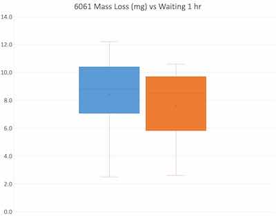
Prior to testing, specimens were conditioned in the test environment, but did not have to be conditioned with temperature & humidity controls. After the 10,000-cycle abrasion test, mass loss was recorded immediately and after waiting 1 hour. The following data summarizes the results generated for Method A (a boxplot is shown for alloy 6061):
| 1100 | 2024 | 6061 | 7075 | |||||
| Immediate | Wait 1 hr | Immediate | Wait 1 hr | Immediate | Wait 1 hr | Immediate | Wait 1 hr | |
| Mass Loss | 9.2 mg | 8.3 mg | 15.0 mg | 14.1 mg | 8.4 mg | 7.6 mg | 12.8 mg | 12.4 mg |
| Std. Dev. | 4.3128 | 4.3458 | 2.5090 | 2.1007 | 2.5522 | 2.4832 | 2.9577 | 3.3984 |
The study also included a series of tests with a break-in period as specified in Method B. This was to determine if the outer surface of an anodized specimen was softer or less dense, which would be shown as generating greater mass loss in the first 1,000 cycles compared to the remaining cycles. Two different alloys (2024 & 7075) anodized by two different anodizers were evaluated. In all cases, the initial 1,000-cycle abrasion mass loss was higher than the average wear index of the remaining abrasion cycles.
| Reference Material | Avg. mass loss after 1000 cycles | Avg. wear index of 10000 cycles |
| 2024 (anodizer 1) | 3.83 mg (σ = 1.0628) | 1.46 mg (σ = 0.3171) |
| 2024 (anodizer 2) | 8.50 mg (σ = 3.8398) | 2.98 mg (σ = 0.7078) |
| 7075 (anodizer 1) | 2.62 mg (σ = 0.8566) | 1.45 mg (σ = 0.4024) |
| 7075 (anodizer 2) | 2.80 mg (σ = 1.2984) | 1.53 mg (σ = 0.4297) |
What is the Next Step?
To assist in the approval process, companies rely on test data – specifically the abrasion resistance information that is typically reported by the anodizer or an independent laboratory. When used as part of quality and process control, having confidence in the test results is essential to ensure your manufacturing process is in control and to avoid defects or costly warranty claims.
To ensure the abrasion procedure referenced in MIL-PRF-8625F is robust, the following updates were submitted as recommended changes. [At the time this article was written, these changes had not yet been approved or adopted.]
Excerpts from MIL-PRF-8625F Nov 20, 2020 (superseding MIL-A-8625F Sept 15, 2003)
- 4.3.3.2.4: Test specimens for abrasion resistance. Abrasion resistance shall be determined on type III production parts or specimen panels (see 4.3.3.2). When specimen panels are used, they shall have having a width of 4 inches, a length of 4 inches, and a minimum nominal thickness of 0.063 inch. Both surfaces shall be plane and parallel, and the panel shall include a 0.25 inch hole centrally located.
- 4.5.5: Abrasion resistance. Test specimens, prepared in accordance with 4.3.3.2.4, shall be tested in accordance with ASTM B1023 – Method A for 10,000 cycles using CS-17 wheels, and accessory weights attached to each abraser arm to apply a load of 1,000 gram per wheel. ASTM D4060 using CS-17 wheels with a 1,000 gram load. The wheels shall revolve on the anodic coating at a speed of 70 revolutions per minute (RPM) for 10,000 cycles. The abrasion wheels shall be refaced prior to each test at least once every 10,000 cycles. The wear index shall be determined after the 10,000 cycle period by dividing the weight loss by 10. The wear index shall meet the requirements of 3.7.2.2.
Where Can Readers Find More Information?
Other test methods used to evaluate abrasion resistance of anodized aluminum using the Taber Abraser include:
- AMS 2469; Hard Anodic Coating Treatment of Aluminum and Aluminum Alloys – Processing and Performance Requirements
- ASTM B1023; Standard Test Method for Abrasion Resistance of Hard Anodic Coatings by a Taber-Type Abraser
- BS 5599; Specification for hard anodic oxidation coatings on aluminium and its alloys for engineering purposes
- ISO 10074 (annex B); Specification for hard anodic oxidation coatings on aluminum and its alloys
- MIL-PRF-8625 (section 4.5.5); Anodic Coatings for Aluminum and Aluminum Alloys
- UNI 7996 (appendix B); Anodic oxidation coatings on aluminium and aluminium alloys – Hard anodic films of great thickness – Requirements and general instructions of test
More information on ASTM B1023 can be obtained by contacting committee B08 on Metallic and Inorganic Coatings, subcommittee B08.10 on Test Methods. To purchase a copy of ASTM B1023, visit https://www.astm.org/b1023-22.html
Alan Jaenecke has been employed by Taber Industries since the year 2000, and plays a critical role in the company’s Materials Test and Measurement division. More information about Taber Industries can be found at www.TaberIndustries.com
References
- Finishing & Coating, March 11, 2021; Rollout of MIL-PRF-8625 Rev F and Implications for Anodizers by Sjon Westre, PhD and Catherine Munson, PhD
- ASTM International, 100 Barr Harbor Drive, West Conshohocken, PA 19428
- Arlt, H.G., "The Abrasion Resistance of Anodically Oxidized Coatings on Aluminum", Proceedings A.S.T.M., Vol. 40, 1940, pp 967-997.
- Lerner, Moisey, “On Seasonal Fluctuations of Abrasion-Resistance Results for Hard-Anodized Aluminum”, Plating and Surface Finishing – Volume 66, Issue 12, December 1979, pp. 40 – 43
- 2007 Metal Finishers Conference, “Type III Anodize: Reducing Variation in Wear Tests”, Bruce Klinger (presented by Fred Schaedel)
- Correlation Between Abrasion Tests (Following BS 6161 Part 18) and Different Anodizing Conditions; Qualital – Novara (Italy), p. 1