The metallurgy of 7000 series aluminum alloys is presented as it relates to the base metal surface, the interface from which the anodic aluminum oxide (AAO) grows.
 Dr. Jude RungePhenomena which impact the growth and structure of the AAO are presented that explain the nature of interfacial instability. Interfacial instability causes interfacial discontinuities which can appear as blistering and delamination between the base metal and the typically metallurgically integrated oxide finish.
Introduction
Interfacial failures such as filiform corrosion, delamination and blistering are rare at the interface between anodic aluminum oxide and its parent substrate due to fact that anodizing is an oxidation process, not a deposition process such as electroplating, lacquering or coating. There is no open avenue at the interface for the progress of tunneling filaments of corrosion by way of differential aeration cells. However, interfacial discontinuities which manifest as delamination and blistering between the anodic oxide finish and the aluminum base material are well documented defects particularly with anodized 7000 series alloys. Examination of the delaminated areas reveal bright, reflective base metal. See Figure 1.
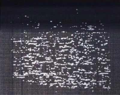 Figure 1: Surface of an alloy 7075 aircraft impeller after subjected to a tape-adhesion test. Sample was heated to 150o C prior to the tape adhesion test. (1)One source for these phenomena has been cited as metallurgical defects (inclusions and coarse phase formation) within the base material (1). However, cracking and spalling of the anodic oxide due to inclusions and coarse phase formation can happen in any alloy where the population and distribution of these defects are sufficient to cause them, and blistering defects are most commonly associated with 7000 series material. Metallurgical defects such as these are ameliorated by monitoring manufacturing and deformation processes of the base material and, with proper pretreatment prior to anodizing.
Hydrogen embrittlement of the aluminum base material due to anodizing is also blamed, but with the current bias of the anodizing process running in a direction such that hydrogen is repelled from the surface, hydrogen will not be absorbed by the substrate during anodizing. As face centered cubic structures, aluminum is not as susceptible to hydrogen embrittlement, aluminum alloys contain no carbon with which the hydrogen can react and aluminum and its alloys dissolve in high pH environments. Therefore, hydrogen embrittlement of aluminum and its alloys is rare, and hydrogen absorption can only happen at the billet level (2).
With the two most common causes in doubt, the question is begged: why would a typically metallurgically integrated oxide cleanly delaminate from the substrate aluminum? In particular, from 7000 series alloys? Extensive research into the reactions and interfacial phenomena which occur during anodizing has led to a theory which presents the mechanism for interfacial discontinuities at the aluminum-anodic oxide interface. The phenomena which impact the growth, structure and interfacial stability of the anodic aluminum oxide (AAO) at the all-aluminum alloy substrate surfaces and in particular, 7000 series alloys, is presented.
Background
The Structure of the Anodic Aluminum Oxide (AAO)
Anodic oxide formation is an electrochemical corrosion process that begins with nucleation at separate and distinct preferential sites across the substrate surface. Preferred sites are those which are not electrochemically complex, neither chemically (sites are comprised of aluminum only) nor topographically (surface is rather continuous with no burrs, laps or seams). In short, an ideal substrate is that which favors oxidation of aluminum.
The oxide nuclei become a network of hydrated, charged flakes that impinge on one another as they grow. As the reaction kinetics continue to favor the initial oxidation sites, exfoliation of the aluminum surface proceeds in an oxidizing atmosphere.
During anodizing, the opposing surfaces of impinging flakes repel one another and grow outward from the substrate surface, forming a unique network of nanoscale corrosion cells. Each cell exhibits the nucleation point at its rounded base; the flakes grow to become column walls which circumscribe a central pore, which has been created by the repulsive forces of the field effects which sustain the finish growth. Proposed by Runge in 2000 (3), Skeldon et al also discuss finish growth via “field assisted alumina flow” (4). Both theories indicate that pore formation is a function of oxide growth and movement by way of field effects rather than by dissolution of the electrolyte. See Figure 2.
![Figure 2: “Constraint” concept of porous oxide finish formation [3]. A: Preferential nuclei form base of pore. B: Repulsive forces between similarly charged oxide “flakes” foster outward growth and initiate pore formation. C: Mass transport and diffusion across column walls form knitlines. D: Repulsive forces within pore maintain the erect nature of the column and dynamic flow of the electrolyte.](/images/images/runge/7000series/2.jpg) Figure 2: “Constraint” concept of porous oxide finish formation [3]. A: Preferential nuclei form base of pore. B: Repulsive forces between similarly charged oxide “flakes” foster outward growth and initiate pore formation. C: Mass transport and diffusion across column walls form knitlines. D: Repulsive forces within pore maintain the erect nature of the column and dynamic flow of the electrolyte.
Figure 2: “Constraint” concept of porous oxide finish formation [3]. A: Preferential nuclei form base of pore. B: Repulsive forces between similarly charged oxide “flakes” foster outward growth and initiate pore formation. C: Mass transport and diffusion across column walls form knitlines. D: Repulsive forces within pore maintain the erect nature of the column and dynamic flow of the electrolyte.
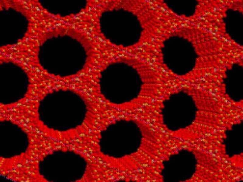
Critical to understanding the reactions that occur during anodizing is the recognition that the anodic oxide is an ionic solid comprised only of hydrated aluminum oxide. The structure exhibits minimal x-ray diffraction contrast, and is therefore designated amorphous but has been shown to exhibit short range order (5), which gives it an almost crystalline character. The anodic oxide structure is comprised only of aluminum and oxygen ions coordinated as AlO4 — tetrahedra which form the “network in the network” of self-assembled, highly ordered nanoscale columns (6). See Figures 3 and 4.
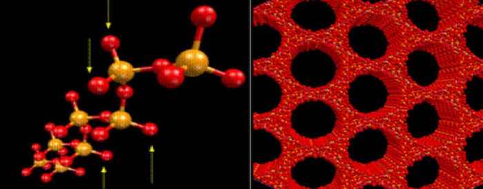 Figure 3: Neutron diffraction done at the synchrotron in Grenoble, France by Kneip, Lamparter, and Steeb in 1989(5) determined each cell of the anodic oxide is comprised of AlO4- tetrahedra with short-range order (periodicity of < 5 units). These tetrahedra comprise the internal network of the individual cells which make up the nanoscale network of the anodic oxide.
Metallurgical Barriers to Anodizing Aluminum
 Figure 4: Schematic of the “network in the network” of the anodic oxide at the anodic oxide cell wall – electrolyte interface (6). The structure of the anodic oxide is that of an ionic solid that facilitates ionic conduction. This conduction enables finish growth. Excess metal ions exist at interstitial sites of the network lattice. Interstitial Al3+ ions migrate together with electrons from the electrolyte during anodizing. Electrolyte reacts with these sites at the surface of the of the pore walls.The aluminum substrate lattice is face centered cubic (fcc), which presents a structural mismatch between the substrate and the forming anodic oxide’s body-centered tetrahedral structure (bct). An aluminum alloy substrate lattice contains non-aluminum atoms in substitutional solution as well as interstitial intermetallic compounds that are not coherent with the microstructure. Since the anodic oxide will not comprise these non-aluminum atoms or intermetallic compounds, a compositional mismatch is also present between the substrate and the anodic oxide.
Another thermodynamic mismatch is present because there are diffusion rate differences between metals and oxides (diffusion occurs faster in metals). Since the substrate is the source for the anodic oxide constituents, and the anodic oxide is the result of the continued reaction of the electrolyte with the substrate surface, the interface of the electrolyte and the surface is the key to continued anodic oxide formation and growth.
In nature, energy is required to overcome a mismatch. Energy produces heat. Non-aluminum metallic ions (copper, zinc, and other metal ions in solution with the aluminum alloy substrate) tend to “pile up” at the interface and must realign themselves as they move from their positions on the substrate lattice to interstitial spaces within the anodic oxide lattice. Once they find a space, they move slower as they “hop” through the spaces in the anodic oxide network while aluminum ion diffusion occurs on the bct lattice which comprises the forming anodic oxide cell. The kinetics of the primary oxidation reaction are therefore retarded during anodizing when non-aluminum elements in solid solution meet the interface at the electrolyte and the substrate surface. (7) See Figure 5.
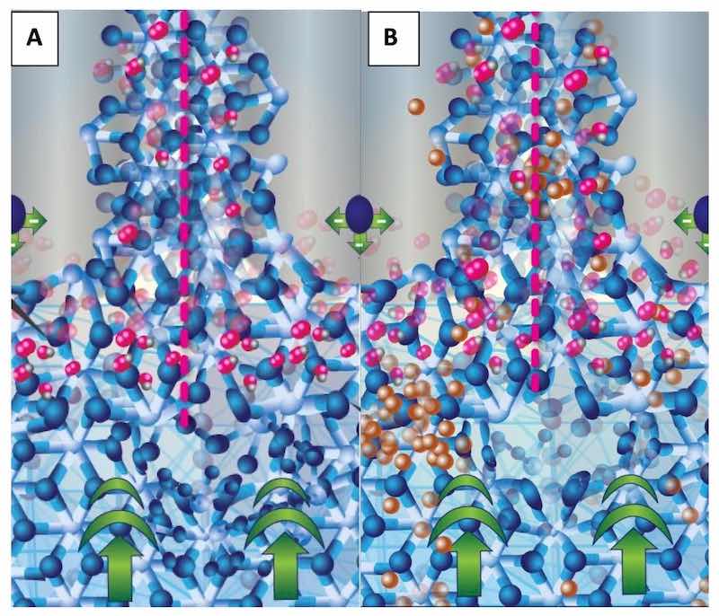 Figure 5: Schematic of the walls of the anodic oxide at the junction of three anodic oxide cells. An entire cell is bracketed with pink dotted lines; the central pore appears gray with repulsive forces represented by a single sphere. The fcc aluminum structure is at the bottom of the schematic with the current bias represented by bold green arrows. The forming bct structure (A and B) exhibits the primary oxidation reaction at the interface between the fcc and the electrolyte in the pore by the presence of oxygen atoms on the bct structure. Schematic B (right) shows non- aluminum ions (copper colored) diffusing from the fcc lattice, through the bct anodic oxide network, into the central pore where it will be carried into the electrolyte. Copper atoms “pile up” at the fcc-bct interface due to the structural/compositional mismatch between the aluminum and the anodic oxide.
Theory
Chemical and Microstructural Considerations of 7000 Series Aluminum Alloys
In general, wrought aluminum alloys that contain additional elements to zinc offer the highest combination of strength and fatigue resistance, based upon intermetallic compounds that form with magnesium, copper, chromium, and manganese. Such aluminum alloys are classified as 7000 series alloys.
Zinc is never added alone to wrought aluminum alloys; copper and magnesium are always added to form Al-Zn-Mg phases, as well as Mg (Zn,Cu,Al)2, and/or combinations of the phases Al2Cu and Al2CuMg. These intermetallic compounds are distributed throughout the microstructure, which means they also intersect the surface, changing the surface chemical potential for anodizing and overall corrosion resistance.
Copper, magnesium, and/or zinc atoms reside on the aluminum lattice in alloy solution. In fact, as a solid- solution strengthening addition, zinc resides on the aluminum lattice, similar to copper and magnesium. According to Mondolfo, et.al, in alloys with less than three percent zinc, all remains in solid solution. (8) This means that when present at the surface in solid solution with the parent aluminum, copper, magnesium, and zinc atoms will inhibit the anodizing reaction.
Birbilis and Buchheit report the microstructures developed in high-strength aluminum alloys, specifically the 7000 series, are complex, incorporating a combination of equilibrium and non-equilibrium phases. For example, according to the literature researched, depending upon the precise composition of the alloy, trace metal ratios, and heat treat quality (quench and temper), the matrix phase of 7075 aluminum is reported as: Al with 3 to 4 wt% Zn, 2 to 3 wt % Mg, and 0.5 to 1 wt % Cu. (9) This means, that together with Aluminum ions, Zinc, Magnesium and Copper ions will diffuse to the interface during anodizing, but have to migrate or “hop” through the forming anodic aluminum oxide (AAO) or otherwise will be entrained at the interface.
The Diffusion of Anodizing 7000 Series Aluminum: How Interfacial Discontinuities Can Form at the Boundary between the Base Material and the AAO
![Figure 6: Schematic of an aluminum lattice with substitutional magnesium and silicon atoms. Note how the variation in size causes compressive and tensile stress within the crystal lattice. Also note the corresponding change in the adjacent lattice parameters, both bond length and interstitial space. [Figure courtesy of the AAC (10)].](/images/images/runge/7000series/6.jpg) Figure 6: Schematic of an aluminum lattice with substitutional magnesium and silicon atoms. Note how the variation in size causes compressive and tensile stress within the crystal lattice. Also note the corresponding change in the adjacent lattice parameters, both bond length and interstitial space. [Figure courtesy of the AAC (10)].Atomic and ionic radii vary from element to element. As atoms of various sizes sit on the aluminum crystal lattice, the amount of distortion introduced to the lattice by the compression or tension introduced by these atoms, causes differences in mechanical properties. The average lattice parameter is governed by the size of the atom on the lattice. A substitutional atom with a different atomic radius will change the adjacent lattice parameters. See Figure 6.
Figure 6: Schematic of an aluminum lattice with substitutional magnesium and silicon atoms. Note how the variation in size causes compressive and tensile stress within the crystal lattice. Also note the corresponding change in the adjacent lattice parameters, both bond length and interstitial space. [Figure courtesy of the AAC (10)].Atomic and ionic radii vary from element to element. As atoms of various sizes sit on the aluminum crystal lattice, the amount of distortion introduced to the lattice by the compression or tension introduced by these atoms, causes differences in mechanical properties. The average lattice parameter is governed by the size of the atom on the lattice. A substitutional atom with a different atomic radius will change the adjacent lattice parameters. See Figure 6.
If the bct structure of the AAO is strictly considered (see figure 3), on which there is one (1) aluminum ion (ionic radius = RAl3+ = 67.5pm) for four (4) oxygen ions (RO2- = 126pm), the bond length will be fixed and yield interstitial spaces of a fixed size. Diffusion would occur through these interstices, which, by virtue of the semiconductor nature of the AAO, would be by vacancy mechanism. Therefore, the size of the holes in the AAO structure limits the diffusion of alloy ions through its structure, outward from the substrate, into the electrolyte.
The AAO unit cell directly adjacent to the substrate would have the pyramidal structure of a body-centered tetragonal crystal. By assigning values to the lattice parameters based in the size of the atomic radii, an interstitial volume can be calculated that exceeds the volume of the largest alloy base metal ion that will be presented at the interface, and not incorporated on the AAO short-range lattice. In other words: zinc, copper and magnesium will diffuse through the spaces in the AAO structure.
The ionic radii specific to the primary alloying elements for the 7000 series, specifically zinc, copper and magnesium are 88, 87 and 86pm respectively; 22% – 23% greater than the aluminum ion (11). As substitutional atoms on the aluminum lattice, the atoms place compressive stress on the face centered cubic (fcc) structure, increasing the energy and therefore, diffusivity through the crystal. During the anodizing reaction, the diffusivity of the substitutional atoms increases as the diffusivity of the aluminum atoms on the primary lattice increases. At this point in time within the substrate, diffusion is quite high, and is taking place by an interstitial mechanism for all atoms, with the smallest atoms (the aluminum) having the highest rate. However, when they reach the free surface at which oxidation takes place, diffusivity for all atoms is decreased, with the aluminum continuing as fastest on the forming bct lattice. The excess interstitial atoms of zinc, copper and magnesium are “injected” at the interface; and their diffusivities immediately decrease (12). Some atoms will find their way through the AAO structure, diffusing by way of vacancy mechanism, to the electrolyte and others will remain at the interface of the base metal. As these ions accumulate at the interface, they inhibit the oxidation of underlying aluminum, and can oxidize themselves. See Figure 7.
The size and extent of “puddles” of injected interstitial alloy atoms that remain at the interface determine if the AAO structure will become discontinuous with the substrate. Certainly as the reaction proceeds, the aluminum around the puddles will continue to be anodized, supporting the neighboring interface. And the accumulation of nonaluminum ions can similarly oxidize, creating localized stress risers across the interface. The oxide appears sound across the entire surface area, but thermal cycling or exposure to high temperatures followed by a tape adhesion test easily delaminates the finish, revealing blister-like defects in the oxide.
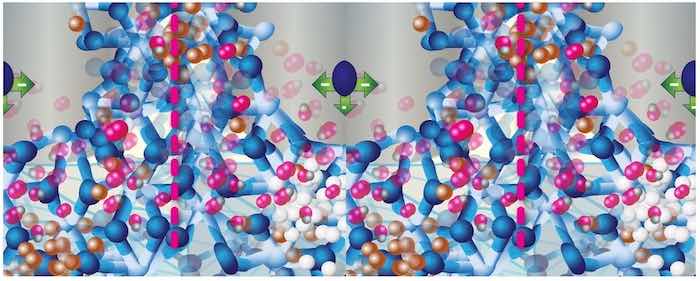 Figure 7: Schematic depicting the entrainment of zinc (white balls) and copper atoms at the fcc (aluminum alloy) - bct (AAO structure) interface.
How Other Atomic Level Defects Can Cause Interfacial Discontinuities
 Figure 8: Schematic shows a hole at the interface between the substrate and the forming AAO.The density of dislocations and vacancies in metal can be quite high, and will diffuse with metal ions. With the imposed current bias during anodizing, the population of these defects will increase as the free surface of oxidation is approached, relative to the bulk of the substrate. A heavily deformed substrate will exhibit “puddles” of dislocations, especially in regions adjacent to and within grain boundaries where the energy is lowest. These concentrations of point defects move along these high diffusivity paths.
It is important to remember that these defects are moving pockets of empty space. As they intersect the free surface of oxidation, they inhibit oxidation as well. If the local density of defects is high, the AAO structure above the puddle will become discontinuous with the base metal. The reaction proceeds through the defect area with some resistance heating, leaving a hole in the AAO, or at the interface with the substrate. See Figures 8 and 9.
Related Interfacial Phenomena
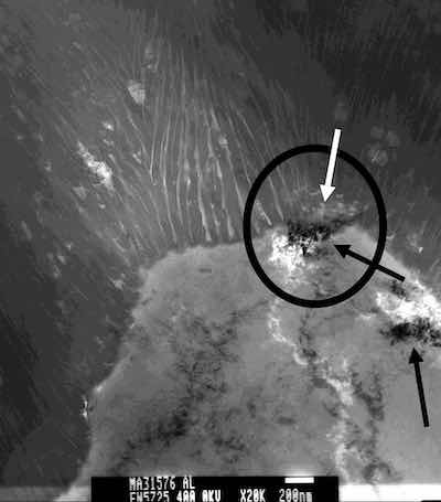 Figure 9: TEM photomicrograph of a “puddle” of dislocations at a triple point between two grains and the free surface from which the AAO structure is grown. Note a discontinuity (hole) at the interface is the result (white arrow); there is no contact between the AAO and the substrate at this point. The black arrows indicate each puddle captured in this section.It is important to note that the remaining components of the microstructure - inclusions, intermetallic compounds, precipitates, and other insoluble alloying elements - are not anodized; instead, the primary oxidation reaction proceeds around them, taking them up into the anodic oxide by way of mass transport. The defects are never incorporated into the AAO structure. The impact of inert or insoluble defects such as inclusions and microconstituents that are not soluble in the aluminum matrix (e.g. lead and hypereutectic silicon) on the finish is 1) in the spacing of the initial corrosion nuclei that precede the anodic oxide network, and 2) in the coherency of the AAO structure. This disruption in order can lead to irregular growth and irregular inter-column spacing. However, as the surface is consumed, the defect is included in the finish, a more ordered surface is presented for oxidation and the oxide growth recovers. The surface of the oxide often replicates the defect, making the surface rougher. Reduced cohesion within the finish leads to chipping, cracking and spalling around the defect, causing finish loss.
Constituent phases form from the parent melt during alloy solidification, and always contain the major parent elements, in this case, aluminum. They are large compared to precipitates and dispersoids, and become aligned with the direction of subsequent thermo-mechanical deformation processes such as extrusion. These phases are often grouped in bands. Because they are rich in non-aluminum elements, the bands have different electrochemical properties than the matrix. As an electrochemical process, anodizing develops these bands differently from the matrix and they appear as dark streaks, an objectionable defect related to the anodizing process that is completely related to the metallurgical condition of the aluminum base material. Typical constituent phases within 7xxx alloys are Al7Cu2Fe and Al2Cu Mg.
Dispersoids are the smallest particles comprising alloying elements that are highly insoluble in aluminum, they are reported to range in size from 0.05μm to 0.5μm. Cr, Ti, Fe, Mn, and Zr are typical dispersoid formers with those containing Fe and Mn being the least passive in environments where aluminum is used. The role of dispersoids is that of a recrystallization inhibitor, and therefore their presence enhances the strength of the alloy. Simply put, dispersoids constrain grain growth. Al3Fe and Al6Mn intermetallic particles are well documented as causing surface pits during anodizing. (13)
Side reactions during anodizing due to the presence of metallurgical interfacial phenomena retard the kinetics of the primary aluminum oxidation reaction, but the level of impact depends on the amount and distribution of incoherent defects. Less energy (heat of reaction) is required at the interface to overcome incoherent defects than the energy required to overcome the effects of substitutional elements in solution with the substrate on the anodic oxide formation and growth. The defects caused are not the same as the interfacial discontinuities caused by excess alloying element ions or other atomic level defects accumulating at the interface with base material.
Summary and Conclusion
Why would a typically metallurgically integrated oxide cleanly delaminate from the substrate aluminum, in particular, from 7000 series alloys?
Non-aluminum ions from all alloys become entrained at the interface between the forming anodic oxide and the parent base material. Depending upon the amount and distribution of these ions, they will resume diffusion through the AAO by jumping through holes within the short range bct lattice. If the ions accumulate at the interface, local oxidation of the adjacent aluminum is inhibited, forming a discontinuity with the substrate. If the substrate is thermally cycled, or heated and dehydrated, the AAO will crack at these discontinuities, and be delaminated by a tape adhesion test.
Aluminum alloys contain one or more of the primary alloying elements; copper, magnesium and zinc, in solution with the base material will individually increase the interfacial resistance to the anodizing reaction. The 7000 series alloys contain all three of the alloying elements, and pose the greatest interfacial challenge to the anodizing reaction of all the wrought alloys. As such, these alloys have the greatest predisposition for these diffusion-related interfacial phenomena.
The faster the current is ramped up for anodizing, the faster the diffusion of the substrate ions to the surface, and the faster the anodic oxide grows. This means alloying element ions will be left behind at the interface to accumulate at a greater rate. This causes the interfacial discontinuities which offer opportunity for delamination through testing or application, as described above. A slow ramp will give time for the non-aluminum ions to begin their diffusion trek through the forming AAO. An occasional pulse, bringing the current density to a lower level, or even to zero for a short amount of time ( ~ 30 seconds to 1 minute), will allow the interfacial resistance heat to dissipate, and also allow for accumulated non-aluminum ions, especially zinc, to migrate forward. This is because the AAO only allows for current to flow in the direction of the bias and that momentum will continue even when the current is briefly reduced or turned off. (14)
As anodizers, there is little else to do to reduce the occurrence of this phenomenon. However, recognition of the source of the problem and positive action to meet the challenge with minor process changes can be effective. Of course, if the source for the problem really is hydrogen embrittlement, a one hour bake at 150°C will diffuse the hydrogen uniformly throughout the part, preventing isolated blisters from forming. Remember, however, the anodizing reaction does not introduce hydrogen to the parts; it actually repels it from the substrate.
References
1. Bocking, Chris, “A Mechanism of Adhesion Failure of Anodised Coatings on 7075 Aluminium”, Surface Technology Support, UK, Proceedings of IHAA Biannual Conference, 2012.
2. Ambat, R. and Dwarakadasa, E. S., “Effect of Hydrogen in Aluminium and Aluminium Alloys: A Review”, Bulletin of Materials Science, Vol. 19, No.1, February 1996, pp. 103 – 113.
3. Runge, J., Pomis, A., “Anodic Oxide Film Formation: Relating Mechanism to Composition and Structure”, Proceedings of the ASST, Manchester, England, May 2000.
4. Skeldon, P., Thompson, G.E., Garcia-Vergara, S.J., Iglesias-Rubianes, L., Blanco-Pinzon, C.E., “A Tracer Study of Porous Anodic Alumina”, Electrochemical and Solid State Letters, 9, (11) B47 – B51, 2006.
5. Kniep, R., Lamparter, P., Steeb, S., Applied Chemistry; 101, Vol. 7, Pages 975-977, 1989.
6. Runge, J.M., “Formation of Porous Anodic Oxide Finishes – A New Approach and Theory”, Proceedings Aluminium 2000, 2007.
7. Runge, J., “Interfacial Phenomena and Anodizing: Ramifications and Process Solutions”, Proceedings of the 17th Annual AAC Conference, San Francisco, California, 2008.
8. Mondolfo, L. F., Aluminum Alloys, Structure & Properties, Butterworth & Co., London, 1976.
9. Birbilis, N., and Buchheit, R., “Electrochemical Characteristics of Intermetallic Phases in Aluminum Alloys and Experimental Survey and Discussion”, Journal of the Electrochemical Society, 152(4), B140 – B151, 2005.
10. AAC Level I Workshop, “Anodizing Essentials”, “Metallurgy Basics for Aluminum Surfaces”.
11. R. D. Shannon, "Revised effective ionic radii and systematic studies of interatomic distances in halides and chalcogenides". Acta Cryst A32: 751–767, (1976).
12. Shewmon, P., Diffusion in Solids, 2nd Edition, McGraw-Hill Series in Materials Science and Engineering, 1989.
13. Runge, J., “Trace Elements and their Impact on Surface Finishing Characteristics of Aluminum Extrusions”, Proceedings of ET 2012, Miami, 2012.
14. Chesterfield, L., “Blistering on 7075 Alloy”, Product Finishing Magazine, November, 2011.
 "The Metallurgy of Anodizing Aluminum" is available at https://link.springer.com/book/10.1007/978-3-319-72177-4 Dr. Jude Mary (Judy) Runge’s career as a metallurgical engineer and surface finishing expert spans almost 40 years in industrial, government and academic professional settings. Beginning in 1982 at Northrop Corporation, Defense Systems Division, and culminating today as a Principal Engineer, Surface Finishing at Apple (since 2019), she is recognized internationally as a nonferrous specialist focusing on materials engineering problem solving that utilizes her expertise as a surface scientist and manufacturing process engineer, providing characterization for product development, failure analysis and metallurgical support to the aluminum finishing industry. She is well known for her work in anodizing that led to a new theoretical treatment for porous oxide formation. Dr. Runge received her Ph.D. in metallurgy at the University of Illinois at Chicago under Dr. Michael McNallan. A tireless educator, Dr. Runge has authored numerous papers and given seminars worldwide; she is the Education Chair for the Aluminum Anodizers Council since 2008. Her book, “The Metallurgy of Anodizing Aluminum”, published by Springer Nature in 2018, is one of her biggest personal achievements. Judy is third of nine children and the first in her family to attend college/university. She is the mother of 4 and grandmother of 8. She believes her success is the result of great personal grit and passion for science, which enabled her hard work and very often, hard decisions. She owes a great deal of her career to her mother, who continuously challenged and supported her. She is grateful to her husband, Thomas Nussbaum, for his love and support and for admitting always how proud he is of her.