Because of its face center cubic (fcc) structure, aluminum readily mixes with other metals in the liquid state; however, the solid solubility of various metals is limited to a few percent.
 Dr. Jude RungeSince no element has complete solid solubility with aluminum, alloying elements form phases with the base aluminum, and/or intermetallic compounds with each other. While main alloying additions develop primary mechanical properties which designate the various aluminum alloy classifications, trace elements are what bring the alloy composition together, refining the characteristics of tensile strength, ductility, corrosion resistance, fatigue resistance, and even surface quality to the finished product.
These small amounts make a big impact on alloy performance; shifts in trace element ratios can drastically change the alloy microstructure. This paper addresses the impact that variations in trace elements can have on the extruded component surface, even within the specification limits for the alloy composition. Changes in the surface chemical potential, caused by these small, but important shifts in composition alter corrosion resistance and finishing characteristics of the extruded component. By characterizing the finishing performance of the alloy with corresponding trace element ratios, lots of material can be identified as “finishing quality”.
Introduction
Alloy Selection for Light Metal Components
Aluminum, magnesium, titanium and beryllium are classified “light metals” as they are frequently used to reduce the weight of components and structures. The property of “lightness” is related to the relative density of the material, 2.7g/cm3 and 1.7g/cm3, for aluminum and magnesium respectively. Upon comparison to the density of other structural metals; 7.9 g/cm3 for iron and 8.9 g/cm3 for copper, it is easy to see why the “light metals” are the preferred materials in the transportation industry, especially in the aerospace and defense industries where minimizing payload weight can reduce fuel consumption and decrease flight time, important economic considerations [1].
In addition to low density, aluminum exhibits a high strength to weight ratio, high corrosion resistance and thermal conductivities. Aluminum is easy to machine and its by-products are not toxic or pyrophoric like those of beryllium and magnesium. It can be alloyed to yield high fatigue resistance. Aluminum is not as expensive as titanium and carbon fiber composite materials. Aluminum, therefore, has become the material of choice for many applications in outdoor recreation products, specifically: bikes, sailboats, ski/walking sticks, fishing equipment, etc.; all benefit from the high strength – to – weight ratio, fatigue resistance in vibration, its impact resistance, and very important: its corrosion resistance.
The source for aluminum’s inherent corrosion resistance is in its high surface reactivity. Aluminum oxidizes readily, producing a stable passive film. The thickness and uniformity of the film can vary, depending upon the conditions under which it has formed. Anodizing is one of the most common processes utilized today which imparts and controls a uniform oxide film of sufficient thickness to enhance corrosion resistance and maintain thermal conductivity. Both cast and wrought products can be anodized with variation in film thickness and quality depending upon chemistry and microstructure. Furthermore, anodizing can be decorated to yield aesthetically pleasing and dynamic-looking finishes.
In the outdoor recreation and sporting goods industry, most assemblies utilize sheet, forged and/or extruded product. Since the focus of this paper is on the use of aluminum extrusions in bicycle components, extrusions only will be considered.
Significance of Wrought Aluminum Alloy and Temper Designations
The IADS (International Alloy Designation System) alloy designation numbering system for aluminum assigns each wrought alloy a four digit number. The first digit is assigned on the basis of the major alloying element(s). The 1XXX series alloys are essentially unalloyed aluminum, with a 99% aluminum minimum. The 2XXX series alloys contain copper as their major alloying element. The 3XXX series, manganese; the 4XXX series, silicon; the 5XXX series, magnesium; the 6XXX series, magnesium and silicon; and the 7XXX series, zinc. The remaining digits indicate variations in the trace element constituents, and for the 1XXX series alone, minimum aluminum purity [2]. Each class of alloys behaves differently, with composition and structure dictating the working characteristics and subsequent properties.
On the role of major alloy additions: Copper, Magnesium, Silicon and Zinc
Wrought alloys must possess a minimum ductility commensurate with the manufacturing process under consideration. Therefore wrought alloys have significantly less alloying elements constitutively and compositionally than cast alloys. For wrought aluminum alloys, the total alloy element loading is less than or equal to 8% the total alloy content, with each alloy addition contributing attributes to the mechanical and chemical performance of the finished product [3].
Copper, as a major alloy addition to the aluminum billet, increases fluidity and decreases the surface tension of the molten pour and aids in producing a billet that is free of hot shortness and porosity. Within the microstructure, copper refines the grain size; that is, the presence of copper in the microstructure prevents excessive grain growth during cooling and heat treatment, producing strength.
Magnesium also increases strength and hardness in the as-cast condition and in work hardenable alloys (the 5000 series) through increased solid-solution hardening. Much greater increases are afforded by artificial aging (precipitation hardening). Silicon is added to almost all wrought aluminum alloys to enhance strength. In fact, the entire 6000 series of wrought alloys are based on precipitate structures of Mg2Si. Other wrought alloys, not considered precipitation hardenable (the 3000 and 5000 series alloys) contain some silicon added to precipitate within the microstructure to enhance strength.
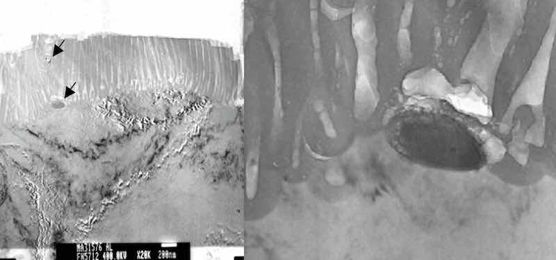 Figure 1: Precipitates which intersect the interface between the aluminum substrate and the anodic aluminum oxide (AAO) are not anodized. The anodizing reaction proceeds around the precipitate, and is included as a non-coherent particle in the AAO. Arrows in the photomicrograph on the left indicate precipitates included in the AAO finish. The photomicrograph on the right documents the activity of the anodizing reaction proceeding around the particle.Precipitates such as Mg2Si are not coherent with the aluminum lattice, and because they do not contain aluminum, they do not anodize under the conditions of a conventional anodizing process, yet they don’t confound the anodizing reaction. Instead, the anodizing reaction proceeds around incoherent intermetallic compounds, and they are taken into the anodic aluminum oxide (AAO) structure. See figure 1.
In general, wrought aluminum alloys that contain additional elements to zinc offer the highest combination of strength and fatigue resistance, based upon intermetallic compounds that form with magnesium, copper, chromium and manganese. In alloys that contain zinc, copper and magnesium are always added to form Al-Zn-Mg phases as well as Mg(Zn,Cu,Al)2, and/or combinations of phases Al2Cu, Al2CuMg. These intermetallic compounds are distributed throughout the microstructure, which means they also intersect the surface, changing the surface chemical potential for anodizing and overall corrosion resistance.
Copper, magnesium and/or zinc atoms reside on the aluminum lattice in alloy solution. In fact, as a solid-solution strengthening addition, zinc resides on the aluminum lattice similar to copper and magnesium. According to Mondolfo, et.al, in alloys with less than 3% zinc, all remains in solid solution [4]. This means that when present at the surface in solid solution with the parent aluminum, copper, magnesium and zinc atoms will inhibit the anodizing reaction. For example, during anodizing of 7000 series alloys, zinc can become entrained at the interface between the substrate and the anodic oxide, causing blisters and delamination of the AAO.
On the role of trace alloy additions
While main alloying additions develop primary mechanical properties which designate the various aluminum alloy classifications, trace elements are what bring the alloy composition together, refining the characteristics of tensile strength, ductility, corrosion resistance, fatigue resistance, and even surface quality to the finished product. These small amounts make a big impact on alloy performance; shifts in trace element ratios can drastically change the alloy microstructure.
The mechanism by which trace elements function is to combine with major alloying elements to form intermetallic compounds as precipitates, constituent phases and particles or dispersoids [5]. These various microstructural phenomena act to: pin grain boundaries and inhibit recrystallization, thereby imparting strength; pin dislocations and impede lattice movement during deformation, thereby imparting rigidity (reducing ductility); increase passivity, thereby increasing corrosion resistance.
The most common trace element added to aluminum alloys is iron. The solubility of iron in the solid state is very low in aluminum (~0.05%), therefore, most of the iron present in aluminum over this amount appears as an intermetallic second phase in combination with aluminum and other elements. Intermetallic compounds comprised of Aluminum-Silicon-Iron strengthen and increase the wear resistance of cast product. Because iron reacts with the aluminum and silicon to make a second phase, the structures tend to be finer than alloys with reduced iron content.
Manganese is the primary alloy addition to the 3000 series wrought aluminum alloys. It increases the strength of the alloy in solid solution with the aluminum. As a trace element, manganese binds with Fe to stabilize the FeAl6 phase in heat treatable alloys, which modifies the microstructure by keeping the intermetallic phase from becoming needle-like or plate-like, which reduces die wear and makes the alloys easier to anodize. As a modifier, manganese forms second phase constituents which precipitate, not to harden, but to retard or inhibit recrystallization. Manganese follows iron as the next most common trace element found in aluminum alloys.
Chromium has a slow diffusion rate and forms fine dispersoids in wrought products. Dispersoids inhibit nucleation and grain growth. Chromium is used to control grain structure, to prevent grain growth in aluminum-magnesium alloys, and to prevent recrystallization in aluminum-magnesium-silicon or aluminum-magnesium-zinc alloys during hot working or heat treatment [6]. Chromium and titanium are added in small amounts to inhibit nucleation of new grains as well as grain growth. Together with magnesium, chromium and titanium produce precipitates that enhance mechanical properties. Such additions can enhance the surface characteristics for anodizing.
Alloy 7075 T6 – Specific Chemistry and Thermodynamics
The following case study deals specifically with aluminum alloy 7075 T6. The 7XXX series alloys are unique in that they incorporate zinc as the major alloying constituent, together with magnesium and copper to achieve the properties of high strength and fatigue resistance. The standard alloy chemistry is provided in Table I. The T6 temper indicates the material has been solution treated and artificially aged to a stable hardness of 87 HRB [7].
Table I: Standard Chemistry for Aluminum Alloy 7075 [2]
| Alloy 7075 | Si | Fe | Cu | Mn | Mg | Cr | Ni | Zn | Ga | V | Zr+Ti | OE | OT |
| Standard | 0.40 | 0.50 | 1.2-2.0 | 0.30 | 2.1-2.9 | 0.18-0.28 | ... | 5.1-6.1 | ... | ... | 0.25 | 0.05 | 0.15 |
Birbilis and Buchheit report the microstructures developed in high strength aluminum alloys, such as 7075, are complex, incorporating a combination of equilibrium and non-equilibrium phases. According to the literature searched, depending upon the precise composition of the alloy, trace metal ratios, and heat treat quality (quench and temper), the matrix phase of 7075 aluminum is reported as Al (3 – 4 wt%) Zn (2 – 3 wt %) Mg (0.5 – 1 wt %) Cu and the following intermetallic compounds have been documented in alloy 7075, although not all simultaneously present: Mg2Si, MgZn2, Mg2Al3, Mg(AlCu), Al20Cu2Mn3, Al12Mn3Si, Al7Cu2Fe, Al2Cu, Al2CuMg, Al3Fe, Al12Mg2Cu, Al6Mn, Al3Ti, Al6Zr, and Al32Zn49. These intermetallic compounds are present as precipitates, dispersoids or phases [8].
Precipitation can best be described as decomposition of a supersaturated solid solution into its parent phase and excess rejected solute atoms [9] The rejected solute atoms agglomerate to form a small crystal of their own, perhaps with a few solvent atoms dissolved in it, or react with some of the solvent atoms to form a phase with a crystal structure different from that of either pure metal (i.e. an intermetallic compound). The agglomerate is the precipitate. It enhances the hardness of the soft matrix by increasing local stress within the microstructure by restricting dislocation movement across the crystal.
Precipitates originate as spheres, heterogeneously and preferentially nucleating throughout the microstructure, and progressively “ripen” during aging (tempering) from spheres to needles, to rods, to platelets. Corresponding to precipitate ripening is an increase in hardness, with peak hardness reached just before platelets are formed. A decrease in hardness is noted after the formation of the equilibrium phase. With extended tempering or over-aging, precipitates will migrate to the grain boundaries, creating a sensitized condition, predisposing the alloy to intergranular corrosion and stress corrosion cracking. Typical precipitates that form in 7000 series alloys are: Mg2Si, MgZn2, Ag2Al3, and Al2Cu.
Constituent phases form from the parent melt during alloy solidification and always contain the major parent elements, in this case, aluminum. They are large compared to precipitates and dispersoids and become aligned with the direction of subsequent thermo-mechanical deformation processes such as extrusion. These phases are often grouped in bands. Because they are rich in non-aluminum elements, the bands have different electrochemical properties than the matrix. As an electrochemical process, anodizing develops these bands differently from the matrix and they appear as dark streaks, an objectionable defect related to the anodizing process that is completely related to the metallurgical condition of the aluminum base material. Typical constituent phases within 7000 series alloys are Al7Cu2Fe and Al2Cu Mg.
![Figure 2: SEM/EBSD grain mapping performed by Zhu, et.al. document that primary dispersoids inhibit recrystallization[10].](/images/images/runge/traceelements/2.jpg) Figure 2: SEM/EBSD grain mapping performed by Zhu, et.al. document that primary dispersoids inhibit recrystallization[10].Dispersoids are the smallest particles comprising alloying elements that are highly insoluble in aluminum, they are reported to range in size from 0.05 to 0.5μm. Cr, Ti, Fe, Mn and Zr are typical dispersoid formers with those containing Fe and Mn to be the least passive in environments where aluminum is used. Al3Fe and Al6Mn intermetallic particles are well documented as causing surface pits during anodizing. The role of dispersoids is that of a recrystallization inhibitor, and therefore their presence enhances the strength of the alloy. Simply put, dispersoids constrain grain growth. See figure 2. [10]
Figure 2: SEM/EBSD grain mapping performed by Zhu, et.al. document that primary dispersoids inhibit recrystallization[10].Dispersoids are the smallest particles comprising alloying elements that are highly insoluble in aluminum, they are reported to range in size from 0.05 to 0.5μm. Cr, Ti, Fe, Mn and Zr are typical dispersoid formers with those containing Fe and Mn to be the least passive in environments where aluminum is used. Al3Fe and Al6Mn intermetallic particles are well documented as causing surface pits during anodizing. The role of dispersoids is that of a recrystallization inhibitor, and therefore their presence enhances the strength of the alloy. Simply put, dispersoids constrain grain growth. See figure 2. [10]
The intermetallic compounds which have the greatest impact are those in the greatest proportion, either by size or population. How and where the particles and phases agglomerate and concentrate impact their size and distribution within the aluminum matrix impacts the chemical potential from point to point across the microstructure. Because these intermetallic compounds are rich in alloying elements, the chemical potential in areas where there are high concentrations can be very different from that of the matrix, creating significant differences in electrochemical behavior and therefore, differences in response to the anodizing process.
Anodizing Aluminum
Under typical atmospheric conditions, a native oxide or passive film naturally forms on aluminum. The native oxide layer is nonuniform and thin. Nevertheless, the native oxide film imparts a certain level of corrosion protection, provided the environment contains no unusual contaminants. Exfoliation, the formation of a network of oxide flakes or “leaves” on the aluminum surface is an example of how corrosion of the surface can be changed through the introduction of sulfur to the environment. In fact, removing sulfur from the atmosphere can control the exfoliation of aluminum [11, 12, 13].
Anodizing can be viewed as the deliberate, controlled corrosion of the aluminum surface in sulfuric acid to yield a uniform, continuous protective oxide film. By adjusting the electrolyte chemistry and the oxidation parameters of time and temperature, various types of anodic finishes are achieved. Type I, or chromic acid anodizing has a distinctly different microstructure than Type II, or technical anodizing, than Type III, or hard anodizing. Its unique columnar structure has been extensively studied, and a mechanism for the anodic oxidation of aluminum is presented herein based on intensive microstructural and chemical analyses of various types of anodized aluminum coatings. The results provided increased insight regarding the mechanism for anodic film formation as well as its resultant chemistry.
Surface Reconstruction
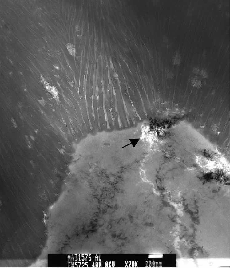 Figure 3: TEM photomicrograph of anodic oxide finish on a 6061 T6 substrate. Arrow indicates a cluster of point defects which disrupted uniform formation of the anodic oxide finish.A comprehensive thermodynamic treatment of chemisorption, which precedes surface oxidation, is presented in Murr [14]. It is important to note that the resultant “infant” oxide layer begins at nucleation sites that may have a preference for certain crystallographic surface orientations as well as surface structural features such as dislocations, steps, or ledges. Temperature impacts nucleation such that fewer preferential sites will form at lower temperatures. At the nano-scale, it has been shown that grain boundaries, inclusions and other forms of surface contamination will also impact the initiation of the oxidation reaction [15]. See figure 3.
It is at this point in the anodizing reaction that electrochemical differences within the substrate microstructure will interfere with finish formation. The increase in point-to-point surface resistance caused by the difference in chemical potential between the precipitate and the matrix can alter the level of chemical attack by the electrolyte as well as the corrosion mechanism (exfoliation) that normally sustains anodic oxide nucleation and growth. Typically, if the defects are small enough, the reaction will occur around the precipitates and the precipitate will be included in the finish. If the microstructural defects are coarse enough, as in the case of over-aged material, which exhibit coarse precipitates concentrated at the grain boundaries (sensitized), the grain boundaries will exhibit preferential attack during pretreatment. If the alloy microstructure is segregated with bands of constituent phases, these regions will exhibit preferential attack during pretreatment. Anodizing develops the metallurgical condition of the substrate, and areas of heavily segregated material will be accentuated, yielding an unacceptable appearance [16]. See figure 4.
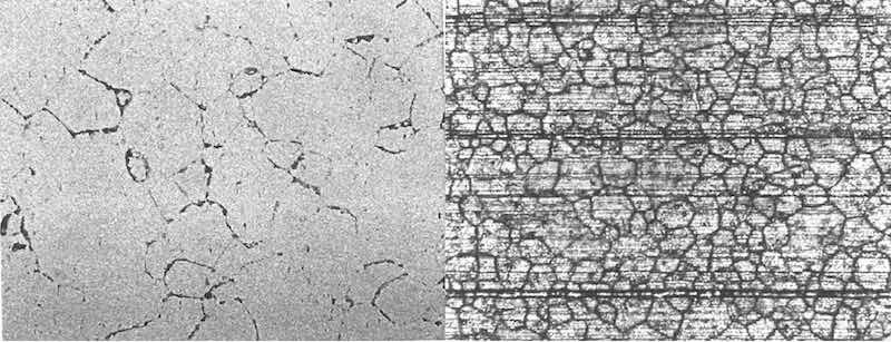 Figure 4: (left) X400, etchant: Tucker’s Reagent. Microstructure of alloy 6061 T6 extruded material exhibiting severe sensitization. (right) X100, as anodized. Anodized surface of sensitized extrusion documented in photo on left.
Case Study [17]
The Effects of Substrate Microstructure on the Anodic Finish
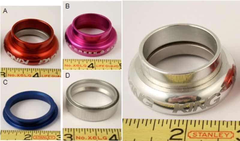 Figure 5: Samples A-D submitted for comparative analysis of the anodic oxide to the clear anodized sample on the far right (note the reflection of the photographer in the component surface). Samples A and B were of acceptable quality, samples C and D were muddy-looking with streaks.Sample bicycle components manufactured from aluminum alloy 7075 T6 extrusions were submitted for evaluation of the surface finish. The components were anodized following Type II anodizing procedures; from an electrolyte of approximately 14% sulfuric acid (180g/l H2SO4), at room temperature (20°C) to varying anodic oxide thicknesses, based upon a qualitative method of clarity/color matching by the end user. Of the groups of components submitted for analysis, the appearance of the anodic oxide on the parts ranged from clear and reflective, even when dyed (Samples A and B), to dark and hazy (Sample C), mottled with streaks and lines (Sample D). See figure 5.
Comparative microstructural analysis as well as measurement of the anodic oxide thickness, hardness testing, and chemical analysis were performed to determine the root cause for variations in surface appearance.
Chemical analysis was performed by way of optical emission spectroscopy per ASTM E1251; Chemical Analysis of Aluminum Alloys. Results are presented in the Table 2.
Table 2: Chemical Analysis Results
| Sample Number %Element* | Si | Fe | Cu | Mn | Mg | Cr | Ni | Zn | Ga | V | Zr+Ti | OE | OT |
| Standard | 0.40 | 0.50 | 1.2-2.0 | 0.30 | 2.1-2.9 | 0.18-0.28 | ... | 5.1-6.1 | ... | ... | 0.25 | 0.05 | 0.15 |
| A | 0.11 | 0.23 | 1.2 | 0.04 | 2.7 | 0.16 | <.01 | 5.5 | ... | 0.0038 | 0.037 | <.01 | .038 |
| B | 0.06 | 0.22 | 1.4 | 0.01 | 2.5 | 0.17 | <.01 | 5.5 | ... | 0.0053 | 0.021 | <.01 | .028 |
| C | 0.06 | 0.21 | 1.5 | 0.01 | 2.4 | 0.16 | <.01 | 5.6 | ... | 0.0069 | 0.021 | <.01 | .025 |
| D | 0.16 | 0.29 | 1.4 | 0.09 | 2.4 | 0.18 | <.01 | 5.5 | ... | 0.0046 | 0.021 | <.01 | .026 |
*In all cases, the essential balance for the alloys tested was aluminum and ranged from 90.0 to 90.1%. OE = other alloy elements, % each. OT = % total other elements within the alloy.
Review of the chemical analysis results determined that the major alloy constituents for the components analyzed were in range or beneath the limit specified. Reduction of silicon, well beneath the specified level indicates that the alloy is formulated for toughness, as all silicon present within the alloy will be reacted to form Mg2Si precipitates, rather than silicon-containing intermetallic phases. Regarding trace elements, chromium is low, especially in Groups A – C, which is in keeping with formulating the alloy for toughness. In fact, it was determined to be just out of specification on the low end. Reduction in chromium correspondingly means a reduction in the grain-boundary pinning dispersoids and therefore a reduction in the propensity to inhibit recrystallization (i.e. the alloys will tend to recrystallize during thermo-mechanical processing). Sample C, however, exhibits a marked increase in vanadium, which will increase the recrystallization temperature for the alloy. Although the iron and manganese are well within the specified range for all sample groups, there is a marked increase in both for the Group D components.
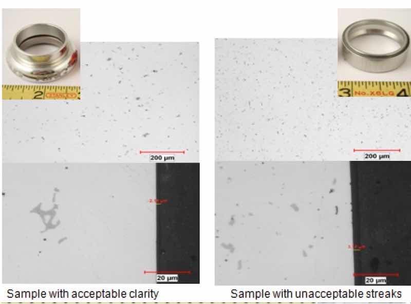 Figure 6: Comparative metallography (unetched) shows a marked difference in the size and population of intermetallic particles.Metallographic analysis of the components revealed that the clear anodized samples were anodized thinnest, from 2μm – 3μm. The colored samples ranged in thickness from 8μm - 16μm. Hardness values ranged from 84 to 87 Rockwell B (HRB), which is within the range for T6 temper. Microstructural analysis determined that unetched, all structures appeared similar except for sample D in which the amount, size and distribution of precipitates and script intermetallic phase were smaller and markedly higher. Energy Dispersive X-ray Spectrographic Analysis (EDS) within the Scanning Electron Microscope (SEM) determined the matrix for the components was in keeping with 7075 alloy: AlMgZn, with dark precipitates being comprised of magnesium and silicon (Mg2Si) and the main intermetallic phase being comprised of aluminum, iron and copper (most likely Al7Cu2Fe, as script phase). See figure 6.
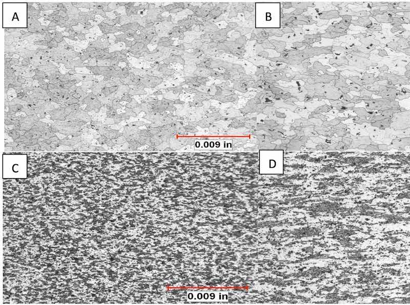
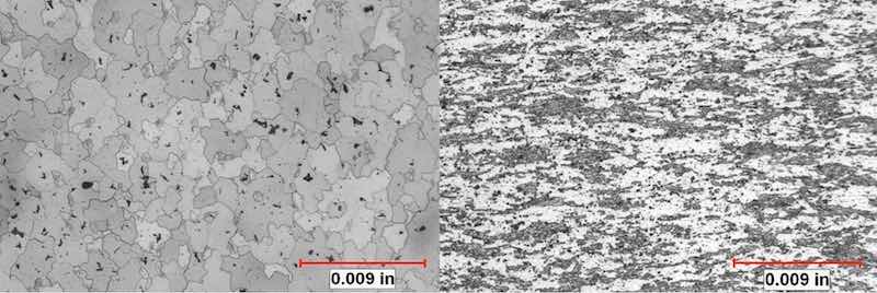 Figure 7: (left) etchant: Keller’s reagent. Microstructure of component with acceptable reflectivity and brightness exhibits equiaxed grains with randomly distributed precipitates. (right) etchant: Keller’s reagent. Microstructure of streaky component exhibits small, deformed dark-appearing areas of constituent phases with adjacent bright-appearing recrystallized grains. Dispersoids are distributed throughout the microstructure, which inhibited recrystallization.
In the etched condition, distinct differences in microstructure were developed that elucidated the differences in the appearance of the components that anodized clear and reflective and those that anodized with a mottled, streaked surface. The grain structure of the samples that anodized with a favorable appearance was equiaxed, with almost total recrystallization. The unfavorable samples exhibited large areas of small, deformed grains oriented in the direction of extrusion. These areas exhibited little to no recrystallization. See figures 7 and 8.
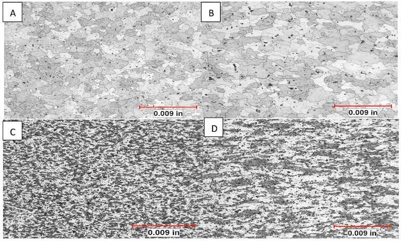 Figure 8: All structures developed with Keller’s Reagent. A) Chemical analysis revealed sample A contained the highest amount of Ti + Zr, the sample exhibits a homogeneous microstructure with dispersoids and equiaxed, fine grain structure. B) Sample B exhibited a structure most like sample A, a exhibited a reflective anodic oxide. C) Sample C exhibited the highest vanadium which raises the recrystallization temperature. Sample exhibits the expected retained deformation (actually, no recrystallization at all). C exhibited a muddy appearance after anodizing. D) Sample D exhibited the highest iron and manganese, relative to the other samples. Sample exhibits partial recrystallization and dipersoid phases throughout the microstructure.
Results and Discussion
Based upon the preceding analysis results, the components with the equiaxed, recrystallized microstructures exhibited the best anodized appearance. The components which exhibited segregation of small, oriented intermetallic phases, with partial or no recrystallization, exhibited the streaked appearance after anodizing. Differences in alloy microstructure most likely developed by differences in trace element concentrations created differences in the chemical potential across the surface of the components, which caused differences in the rate of chemical attack during anodizing.
Areas within the microstructure that are richer in alloying elements change the interfacial resistance developed by the parameters of the anodizing process, which are suited for the nucleation and growth of aluminum oxide only. Deviations in interfacial resistance caused by non-aluminum elements retard the oxide growth rate, and depending on the increase of the resistance, cause finish defects. The level and concentration of alloy additions, constituent segregation, and overall defect population compound resistance effects change the chemical potential of the surface which profoundly impacts the appearance of the anodic oxide finish.
The samples which exhibited unfavorable appearances after anodizing, also exhibited segregation of intermetallic phases, and upward shifts in the trace element contents of iron and manganese (sample D), as well as vanadium (sample C), all which are added to inhibit recrystallization. Constituent phases, such as Al7Cu2Fe, which comprise the dark regions in the anodic oxide finish, are not soluble in the aluminum matrix through thermo-mechanical processes such as extrusion. The small size of the phases, as compared to those in sample A, which anodized with favorable results, suggests no problem with the homogenized quality of the billet prior to deformation processing. Sample C exhibited the highest level of vanadium, which increases the recrystallization temperature, and, it exhibits no microstructural evidence of recrystallization. Dispersoids, formed with iron and manganese within the aluminum alloy, are well documented recrystallization inhibitors, are present throughout the microstructure of sample D and are the most likely source for the pinning of the grains comprised of the primary intermetallic phase, which prevented the recrystallization of the microstructure in these areas.
Conclusion
It is apparent that small shifts in trace elements impacted the surface chemical potentials of the various samples to be anodized. However, all of the samples in the anodizing group were within the standards for the trace elements for aluminum alloy 7075. Hardnesses were measured for each sample and appropriate for a T6 temper. The microstructures of the samples varied significantly and they anodized differently. The observed variation in sample microstructure corresponded to the specific effects brought about by the addition of the specific trace elements.
The only published value for a trace element by which recrystallization is affected is .05% for iron [3]. There are no published values for other trace elements or ratios thereof within specific alloys that produce alteration in microstructure and corresponding reduction in corrosion resistance. Variations in iron and manganese, which produce intermetallic dispersoids that increase the pitting potential of the surface, appear to be the most significant trace elements by which variations impact the microstructure and corrosion resistance. Another element that should be tracked is vanadium as its addition increases the recrystallization temperature of the alloy. By comparing the trace elements between samples with variations in microstructure which impact the surface chemical potential (exhibit pitting, unusual reduction in corrosion resistance or anodize with poor results) trends can be established that can ultimately be used to help identify base material which can be reliably anodized.
Budget constraints prohibited further analysis to document the minor intermetallic phases formed with trace elements in the components; nevertheless, provided that the background processing (homogenization, quench and temper) for all of the submitted extruded components are at least similar, this case study demonstrates well the significant role of trace metals within alloy chemistry and their impact on alloy microstructure.
Acknowledgements
Mr. Josh Coaplen of Cane Creek Cyclery is to be acknowledged for allowing the publication of a summary of the comparative analysis of several bicycle head set components. Cane Creek Cyclery is in Fletcher Creek, North Carolina.
References
- 1. Polmear, I. J., Light Alloys, Metallurgy of the Light Metals, American Society for Metals, 1982.
- 2. ASM International Metals Handbook, Tenth Edition, Volume 2, Nonferrous Metals and Alloys, 1985.
- 3. Davis, J.R., editor, Alloying, Understanding the Basics, ASM International, Materials Park, Ohio, 2001.
- 4. Mondolfo, L. F., Aluminum Alloys, Structure & Properties, Butterworth & Co., London, 1976.
- 5. Brooks, C.R., Heat Treatment, Structure and Properties of Nonferrous Alloys, American Society for Metals, Metals Park, Ohio, 1995.
- 6. Keytometals.com/article55.
- 7. Matweb
- 8. Birbilis, N., and Buchheit, R., “Electrochemical Characteristics of Intermetallic Phases in Aluminum Alloys and Experimental Survey and Discussion”, Journal of the Electrochemical Society, 152(4), B140 – B151, 2005.
- 9. Porter, D.A., and Easterling, K.E., Phase Transformations in Metals and Alloys, Second Edition, Chapman and Hall, 1992.
- 10. Zhu, H., Dahle, A.K., Zhang, X. and Couper, M.J., “Effect of Extrusion Microstructure on Formation of Streaking Defects on the Surface of Anodized Aluminum Extrusions”, Proceedings of the 18th Annual Anodizing Conference and Expo of the Aluminum Anodizers Council, San Francisco, 2008.
- 11. Uhlig, H. H., Corrosion and Corrosion Control, Wiley, New York, 1985.
- 12. Jones, D. A., Principles and Prevention of Corrosion, MacMillan Publishing Company, New York, 1992.
- 13. ASM International Metals Handbook, Tenth Edition, Volume 13, Corrosion, 1985.
- 14. Murr, L., Interfacial Phenomena in Metals and Alloys, Addison-Wesley Publishing Co., 1975.
- 15. Runge, J.M., “Formation of Porous Anodic Oxide Finishes, A New Approach and Theory”, Proceedings of Aluminium 2000, Florence, 2007.
- 16. Runge, J.M., “Base Metal Microstructural Concerns for Aluminum Finishing”, Proceedings of the IHAA Biannual Technical Conference, Lisbon, 1996.
- 17. Runge, J.M., Case Study for Cane Creek Cyclery, Unpublished, 2008.
 The Metallurgy of Anodizing Aluminum" is available at https://link.springer.com/book/10.1007/978-3-319-72177-4 Dr. Jude Mary (Judy) Runge’s career as a metallurgical engineer and surface finishing expert spans almost 40 years in industrial, government and academic professional settings. Beginning in 1982 at Northrop Corporation, Defense Systems Division, and culminating today as a Principal Engineer, Surface Finishing at Apple (since 2019), she is recognized internationally as a nonferrous specialist focusing on materials engineering problem solving that utilizes her expertise as a surface scientist and manufacturing process engineer, providing characterization for product development, failure analysis and metallurgical support to the aluminum finishing industry. She is well known for her work in anodizing that led to a new theoretical treatment for porous oxide formation. Dr. Runge received her Ph.D. in metallurgy at the University of Illinois at Chicago under Dr. Michael McNallan. A tireless educator, Dr. Runge has authored numerous papers and given seminars worldwide; she is the Education Chair for the Aluminum Anodizers Council since 2008. Her book, “The Metallurgy of Anodizing Aluminum”, published by Springer Nature in 2018, is one of her biggest personal achievements. Judy is third of nine children and the first in her family to attend college/university. She is the mother of 4 and grandmother of 8. She believes her success is the result of great personal grit and passion for science, which enabled her hard work and very often, hard decisions. She owes a great deal of her career to her mother, who continuously challenged and supported her. She is grateful to her husband, Thomas Nussbaum, for his love and support and for admitting always how proud he is of her.