The anodization of aluminum is widely used to form an anodic film that endows aluminum with various surface properties beneficial for practical applications.
However, the effects of alloying elements on the structure of the resulting film remain unknown. Additionally, although tempering is widely used to improve the properties of aluminum alloys, its effect on anodization is not fully understood. Thus, to expand our understanding of aluminum alloy anodization, herein, we investigated the anodization in sulfuric acid (1.5 mol dm−3) of 7075 aluminum alloys (AA7075) tempered under different conditions. The anodization behavior of AA7075–T6 (standard sample) was compared with those of AA7075–O, AA7075–T4, and pure aluminum (99.99 %).
The voltage–time curves during constant-current anodization differed depending on the material. The barrier layer formed on AA7075 showed higher porosity than that on high-purity aluminum in the initial stages of anodization. The distribution of the alloying elements (e.g., Zn and Cu) in the aluminum matrix strongly affected the structure and properties of the film. Particularly, in AA7075–T6, the formation efficiency and hardness of the anodic oxide film were notably reduced because the film was highly porous and contained numerous horizontal pores.
Thus, although tempering improves the mechanical properties of aluminum alloys through the formation of fine precipitates within the aluminum matrix, it can have detrimental effects on the properties of anodic oxide films by causing unexpected excessive chemical dissolution of the anodic film.
Original title: Effect of alloying elements on the morphology of anodic films formed on 7075 aluminum alloys tempered under different conditions via anodization in sulfuric acid
1. Introduction
Aluminum alloys are tempered, i.e., subjected to heat treatment, to enhance their properties [[1], [2], [3]]. These alloys undergo annealing, solution annealing, and age hardening, followed by various surface treatments, such as anodization, as the final step in their manufacturing. Aluminum anodization is widely used in practical applications to form an anodic film that endows aluminum with various surface properties, e.g., hardness, wear resistance, adhesion, and coloring [4,5].
The dimensions and characteristics of the anodic film, e.g., pore diameter, pore density, and film thickness, can be adjusted by controlling the anodization conditions, e.g., voltage, current, and duration. Thus, anodization has attracted notable attention in industrial surface treatment and the fabrication of nanomaterial templates [[5], [6], [7]]. However, most academic studies on anodization have employed high-purity aluminum (>99.99 %) to eliminate the effects of alloying elements present in aluminum alloys. At the same time, the anodization of aluminum alloys has been investigated less comprehensively. Several studies have evaluated the corrosion resistance of anodized aluminum alloys and investigated the effects and mechanisms of various sealing techniques [[8], [9], [10], [11], [12]]. In our previous study, we have studied the anodization of aluminum alloys, particularly, optimized the chemical composition of the electrolyte to form a hard anodic film [13].
However, the details on the anodization of aluminum alloys (i.e., the voltage–time curves obtained during anodization at a constant current) and the effects of alloying elements on the microstructure of the formed film, have not been comprehensively investigated. Although tempering is widely used to improve the properties of aluminum alloys, its effect on anodization is not fully understood. Therefore, the specifics of the anodization of aluminum alloys tempered under different conditions must be elucidated to broaden the application scope of aluminum alloys. To provide practical guidance for the aluminum industry, it is essential not only to thoroughly understand the nature of anodization processes but also to accumulate fundamental data.
Herein, the anodization behavior of the 7075 aluminum alloy (AA7075), with Zn, Mg, and Cu as the main alloying elements, was investigated during anodization in an industrial sulfuric acid electrolyte at a constant current. AA7075 is one of the most commonly used aluminum alloys because of its low density, high mechanical strength, and good corrosion resistance. To supplement our understanding of the anodization of aluminum alloys containing intermetallic compounds of various shape, sizes, and compositions, the effects of tempering conditions on the efficiency of the anodic film formation, the film structure, and the film hardness were also investigated. This was done through the analysis of the structure and composition of the anodic films formed on the AA7075 alloy using transmission electron microscopy (TEM) and energy-dispersive X-ray spectroscopy (EDS) on both cross-sectional and plane-view samples. Additionally, the effect of the type and distribution of alloying elements on the structure of the formed films was discussed. Instead of using different alloy types (such as AA2024–T3 and AA7075–T6), the investigation of AA7075 with identical composition but differing tempering conditions revealed the properties of AA7075–T6 in particular. The obtained results indicate that the distribution of alloying elements in the aluminum matrix strongly affected the film structure and properties. Particularly, the formation efficiency and hardness of the film on AA7075–T6 were notably reduced owing to the high porosity of the formed anodic oxide film.
2. Experimental
2.1. Preparation of the anodic films
Specimens from AA7075 aluminum alloy heat-treated to a peak ageing condition (T6 heat treatment, working area 19.94 cm2) were used as standard samples. AA7075–O, AA7075–T4, and a pure aluminum sheet (purity = 99.99 %, Nippon Light Metal Company, Ltd., Japan) were used for comparison. The nominal chemical composition (in wt.%) of the AA7075 alloy is < 0.4 Si, <0.5 Fe, 1.2–2.0 Cu, <0.3 Mn, 2.1–2.9 Mg, 0.18–0.28 Cr, 5.1–6.1 Zn, <0.2 Ti, <0.15 other elements (total), and balance Al.
The specimens were pretreated before anodization as follows. Each specimen was ultrasonically degreased in acetone for 3 min, immersed in a sodium hydroxide solution (5 wt%) at 60 °C for 20 s, and then immersed in a nitric acid solution (30 vol%) for 1 min at room temperature. The samples were rinsed with ion exchange–treated water after each step. The anodization was conducted on undried specimens.
Anodization was performed in a sulfuric acid solution (1.5 mol dm−3) for 60 min at a constant current density (100 A m−2). The electrolyte was stirred using a magnetic stirrer at 300 rpm, and its temperature was maintained at 20 °C using a cooling-water circulator (EYELA, CAP–1000). The anodization conditions were the same as those used in our previous study [13]. The voltage was measured using a digital multimeter equipped with a data acquisition system (Keithley, DMM2700).
2.2. Film structure, formation efficiency, and hardness of the anodic films
The surface and cross-sections of the formed films were observed using field-emission scanning electron microscopy (SEM; JEOL, JSM–6701F). Before SEM observations, the dried samples were coated with osmium using an osmium coater (Meiwafosis, Neoc-Pro). The distribution of alloying elements, i.e., the formation of intermetallic compounds in anodic alumina, was investigated using an atomic resolution analytical electron microscope (JEOL, JEM–ARM200F) and EDS (JEOL, JED–2300T) at an acceleration voltage of 80 kV following the method reported in our previous study [13]. Bright-field (BF) and high-angle annular dark field (HAADF) images were obtained in the scanning TEM mode. The chemical composition of each substrate before anodization was also examined using Auger electron spectroscopy (AES; JEOL, JAMP–9500F). The formation efficiency and hardness of the anodic films were evaluated using the coating ratio and Martens hardness, respectively. The Martens hardness of the anodic films was measured using a dynamic ultra-microhardness tester (Shimadzu, DUH–W201). Details on the calculations of the coating ratio and the Martens hardness may be found in our previous work [13].
3. Results and discussion
3.1. Effect of tempering conditions on the voltage–time curves during constant-current anodization
Fig. 1 shows the AES elemental maps of each substrate before anodization. The distributions of the alloying elements (Zn, Mg, and Cu) on the surface indicate the presence of intermetallic compounds. In the case of AA7075–O, the distribution of the alloying elements in the aluminum matrix is heterogeneous (Fig. 1a). Because this alloy was not previously subjected to solution heat treatment, the alloying elements are not dissolved in the aluminum matrix. In the case of AA7075–T4 and AA7075–T6, the alloying elements are homogenously distributed in the aluminum matrix because of solution annealing (Figs. 1b and c). At the same time, no notable segregation is observed at the surface.
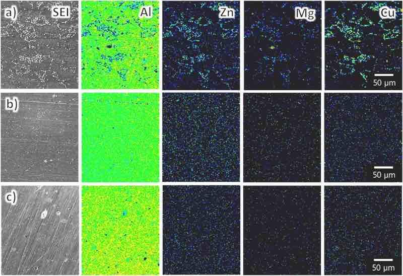
Fig. 1. AES surface elemental maps for each substrate: (a) AA7075–O, (b) AA7075–T4, and (c) AA7075–T6. The magnification is identical in all images.
Fig. 2a shows the voltage–time curves for AA7075 (tempered under different conditions) and high-purity aluminum during anodization at a constant current of 100 A m−2 in sulfuric acid (1.5 mol dm−3). Fig. 2b exhibits an enlarged voltage–time curve of the first minute of anodization. In the case of high-purity aluminum, the voltage increases at the beginning of anodization, peaks at approximately 19 V, and stabilizes at approximately 15 V. This voltage behavior is typical for the constant-current anodization of aluminum [5].
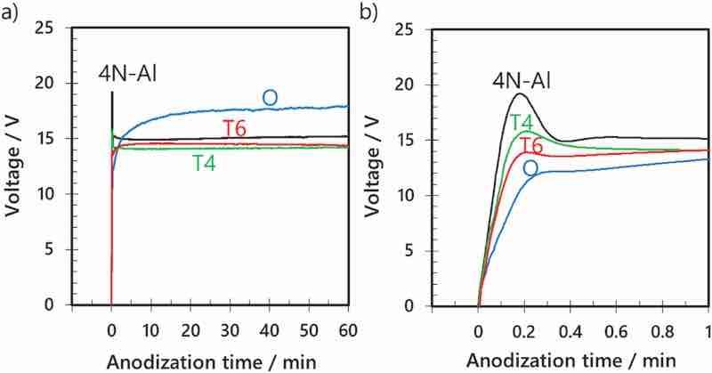
Fig. 2. (a) Voltage–time curves for the anodization of AA7075–O, AA7075–T4, AA7075–T6, and high-purity aluminum in sulfuric acid (1.5 mol dm−3) at a constant current density of 100 A m−2 and a temperature of 20 °C for 60 min. (b) Voltage–time curves for the initial stage of anodization.
However, in the case of AA7075–O, the voltage does not peak at the beginning of anodization: it slowly increases, reaching approximately 18 V after 60 min of anodization. This slow increase in voltage without peaking suggests that the film was not uniformly formed over the entire surface of the sample. This was attributed to the dispersion of the alloying elements in the aluminum matrix (Fig. 1a).
In the anodization of AA7075–T4 and AA7075–T6, the voltage increases at a lower rate at the beginning of anodization and the maximum voltage is lower than those for high-purity aluminum, suggesting that the barrier layer formed on these alloys in the initial stages of anodization is more porous than that formed on high-purity aluminum. In contrast to AA7075–O, the steady-state voltage is reached early during the anodization of AA7075–T4 and AA7075–T6. This was attributed to the uniform distribution of alloying elements in the aluminum matrix (Figs. 1b and c) and thereby a weaker effect of the dispersion state of the alloying elements on the anodization behavior than in the case of AA7075–O.
3.2. Film formation efficiency evaluated in terms of coating ratio
In electrochemical processes, it is desirable to suppress side reactions and increase the current efficiency of the main reaction. Herein, the efficiency of anodic film formation as the main reaction was evaluated using the coating ratio [4,13]. At 100 % conversion efficiency of aluminum to aluminum oxide (alumina, Al2O3), i.e., without unavoidable inefficiencies such as the dissolution of the anodic film and the elution of aluminum ions from the substrate during anodization, the theoretical coating ratio would be = 1.890 [4]. However, owing to chemical dissolution, the coating ratios of AA7075–O, AA7075–T4, and AA7075–T6 were approximately 1.1, 0.79, and 0.83, respectively. The same evaluation was repeated at least two or more times to ensure the repeatability of the coating ratio.
The amount of aluminum consumed during the 60-min anodization was similar in all samples (66–70 mg) because aluminum consumption depends on the charge consumed during anodization (i.e., current density × time). The weights of the anodic films formed on AA7075–O, AA7075–T4, and AA7075–T6 were approximately 78, 54, and 55 mg, respectively. The weights of the films formed on AA7075–T4 and AA7075–T6 are similar but lower than that of the film formed on AA7075–O, indicating that anodic films formed on AA7075–T4 and AA7075–T6 are more prone to chemical dissolution than that formed on AA7075–O. This reflects the differences in the elution degree of the alloying elements into the electrolyte during anodization. The actual film structure will be discussed in further sections. Notably, it has been previously proven that effectively suppressing the chemical dissolution of the anodic film on aluminum alloys during anodization improves film formation efficiency [13].
3.3. Film hardness
The hardness of the formed films was evaluated as one of the key characteristics of anodic films. Specifically, the Martens hardness of the anodic films prepared at a constant current of 100 A m−2 in sulfuric acid (1.5 mol dm−3) for 60 min was measured. Fig. 3a–c show the raw data of the test force (load)–depth (displacement) curves for the anodic film formed on AA7075 tempered under different conditions. Fig. 3d shows a typical load–displacement curve for each sample. The indentation depth of the anodic film on AA7075–O at the maximum test force (F = 100 mN) is 1.8 μm. The indentation depths on A7075–T4 and A7075–T6 are 4.3 and 4.5 μm, indicating lower hardness of these anodic films. The Martens hardness values calculated based on the relationship between the test force and indentation depth at the maximum test force are approximately 1150, 207, and 190 N mm−2 for anodized AA7075–O, AA7075–T4, and AA7075–T6, respectively. These results indicate that the porosities of the anodic films formed on AA7075–T4 and AA7075–T6 are larger than that of the film formed on AA7075–O, resulting in their lower hardness. This lower hardness agrees well with the aforementioned coating ratios.
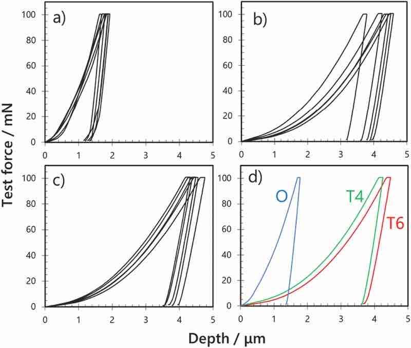
Fig. 3. Load–displacement curves obtained through the indentation tests of anodic films formed on AA7075 tempered under different conditions: (a) AA7075–O, (b) AA7075–T4, (c) AA7075–T6, and (d) representative sample.
3.4. Film structure observed using SEM
To elucidate the effects of film structure on the formation efficiency and hardness of the anodic films formed on AA7075, the film structure was observed using SEM. The anodic films were prepared using the same procedure and conditions as for the hardness test. Fig. 4, Fig. 5 show the surface and cross-sectional SEM images of the anodic films formed on AA7075 tempered under different conditions. In the SEM image of AA7075–O, micrometer-scale depressions with irregular aperture shapes (marked by arrows) are observed on the film surface (Fig. 4a). Nanopores with a diameter of approximately 15 nm were formed inside and around the micrometer-scale depressions (Fig. 4d). The depressions are also observed in the cross-sectional image (Fig. 5a). These depressions were considered to form through the dislodging of intermetallic compounds, which were segregated as shown in Fig. 1a. This indicates that anodized intermetallic compounds dissolved faster than the surrounding anodic alumina.
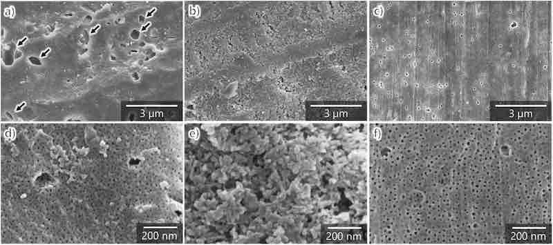
Fig. 4. SEM images of the surface of aluminum specimens anodized in sulfuric acid (1.5 mol dm−3) at 100 A m−2 and 20 °C for 60 min: (a, d) AA7075–O, (b, e) AA7075–T4, and (c, f) AA7075–T6. (d–f) High-magnification images.
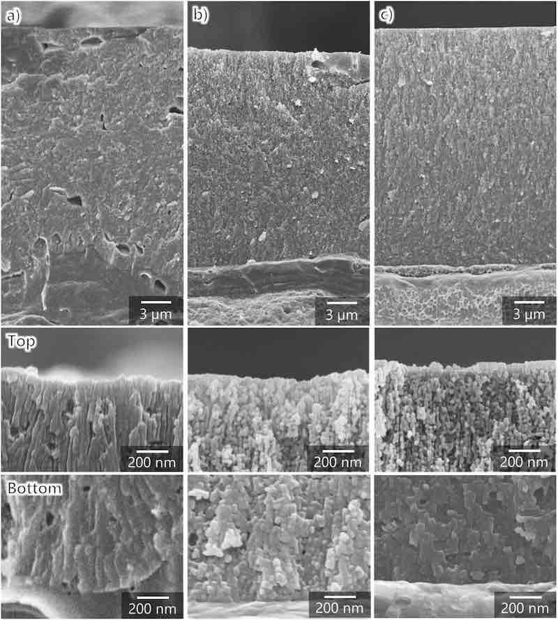
Fig. 5. SEM images of the cross-sections of aluminum specimens anodized in sulfuric acid (1.5 mol dm−3) at 100 A m−2 and 20 °C for 60 min: (a) AA7075–O, (b) AA7075–T4, and (c) AA7075–T6 (the high-magnification images show the surface and bottom parts of the anodic films).
The structure of anodized AA7075–T4 is granular rather than honeycomb-like nanoporous, which is typically formed during anodization (Fig. 4, Fig. 5b). Moreover, no micrometer-scale depressions are observed in AA7075–T6. As shown in high-magnification images, the nanopores in anodized AA7075–T6 are slightly larger (Fig. 4f) than those in anodized AA7075–O (Fig. 4d). At the same time, the cross-sectional view (Fig. 5c) exhibits typical pore alignment (perpendicular to the substrate) and small horizontal pores in the cell walls. Overall, the outer surface of the anodic film was chemically dissolved with increasing anodization duration. The chemical dissolution is more pronounced in the outer layer of anodized AA7075–T6 than in anodized AA7075–O despite the same anodization time (60 min) and electrolyte concentration. Because the pore size in the upper part of the anodic film is larger than that in the bottom part, chemical dissolution during anodization strongly affected the porous structure, film formation efficiency, and hardness of the anodic film. Thus, the decreased film formation efficiency and hardness observed for the anodized AA7075–T6 were attributed to the increase in porosity in the upper part of the film owing to chemical dissolution.
3.5. Effect of alloying elements on film formation
The effects of alloying elements in the aluminum alloy on the film formation during the anodization of AA7075–T6 were further investigated using TEM and EDS. Overall, the formed anodic films exhibit nonuniform and complex structures owing to the incorporation of alloying elements into the cell walls of the anodic film. With the extension of anodization time, the distribution of the alloying elements in the anodic films became more difficult to determine; hence, the anodization was stopped at 60 s to prepare thin films for TEM observations.
Fig. 6 presents the TEM images of the cross-section of the anodic film formed on AA7075–T6. Its BF and HAADF images are shown side by side for a clear comparison of the film structure and chemical composition. The BF image exhibits several black spots of various sizes, whereas the HAADF image shows white spots in addition to submicron-sized voids in the anodic film. A high-magnification image of a portion of the interface between the anodic film and the substrate indicates that voids formed in a particle that was thought not to consist of aluminum. Thus, the reduced formation efficiency and hardness of the anodic film were attributed to the irregular film structure, particularly these voids.
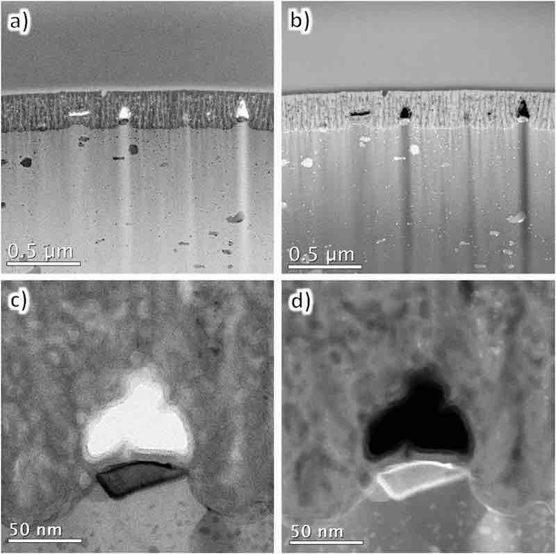
Fig. 6. TEM images of the cross-sections of AA7075–T6 anodized in sulfuric acid (1.5 mol dm−3) for 60 s: (a, c) BF and (b, d) HAADF images. (c, d) High-magnification images.
Fig. 7 exhibits the cross-sectional elemental maps of the film/substrate interface. The analysis area is the same as in Fig. 6c. The maps for eight elements were obtained, among which Al, Mg, Zn, Cu, Si, and Cr originate from the substrate, whereas O and S originate from the electrolyte. The anodic films formed through anodization in sulfuric acid are mainly composed of alumina (Al2O3) and contain anions (sulfate ions), with the electrolyte-derived O and S as well as Al evenly distributed throughout the anodic film.
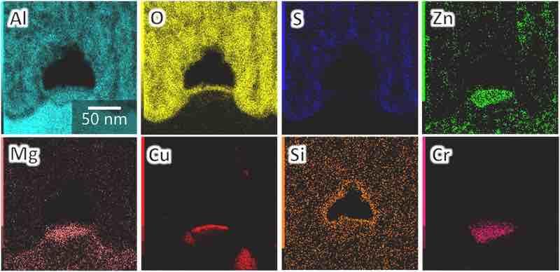
Fig. 7. Elemental maps of the cross-section of the anodic film formed on AA7075–T6 (the analysis area is the same as in Fig. 6c).
Zn, Mg, Cu, Cr, and Al detected at the film/substrate interface (Fig. 7) were considered to form intermetallic compounds (e.g., MgZn2, MgCuZn, Al2Cu, Al7Cr, AlZnMg, and Al2CuMg), which precipitated as second-phase particles in AA7075. More information on the intermetallic particles in AA7075–T6 may be found in previous reports [14,15]. The formation of voids in these intermetallic particles was explained by oxygen generation [[16], [17], [18]]. Zn is well dispersed in the anodic film, and the contents of Mg and Cu in the film are lower than those in the substrate. Moreover, Cu is concentrated on the film/substrate interface, which is typically observed in anodic films [[16], [17], [18]]. The enrichment and oxidation of Cu in the solid solution inhibits pore growth, resulting in the high porosity of the anodic oxide film (numerous horizontal pores), which is generally consistent with previously reported results [17,18].
Fig. 8 shows typical EDS results. The results of the EDS spot analysis of points 1, 2, 3, 4, and 5 indicate the following: point 1 exhibits typical composition of the aluminum matrix; spectra for points 2 and 3 indicate the presence of elements derived from the intermetallic particles (i.e., Al, Zn, Mg, Cu, Cr) in the darker area at the film/substrate interface in the TEM image; spectrum for point 4 suggests that the upper part of the darker area in the TEM image contains Al, O, and S originating from the alumina and sulfate ions as well as Cr and Si; and spectrum for point 5 indicates that the anodic film consists of Al, O, and S. Other elements (i.e., C and Ti) were introduced through contamination with hydrocarbon and TEM grid, respectively.
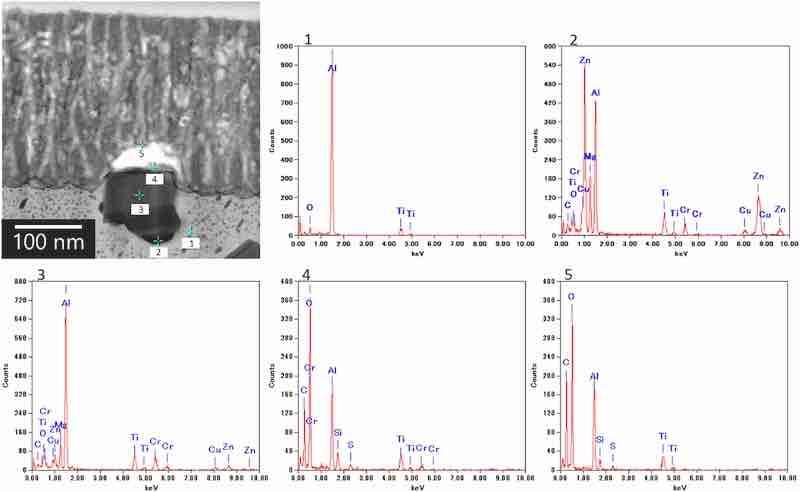
Fig. 8. EDS spectra of the cross-section of the anodic film formed on AA7075–T6. The anodization conditions were the same as those in Fig. 6. The analysis area differs from the area shown in Fig. 6.
These results indicate that Mg and Cu were eluted into the electrolyte during anodization because they are more soluble in the electrolyte than alumina. The preferential dissolution of these alloying elements from finer second-phase particles may be the cause of the formation of voids and small horizontal pores in the cell walls.
3.6. Morphology and chemical composition of the anodic films
To investigate the morphology and chemical composition of the anodic film, a horizontal cross-section of the film was sampled near the barrier layer. The TEM images of such a horizontal cross-section of the anodic film on AA7075–T6 are shown in Fig. 9, exhibiting several lateral voids extending from the center of the main nanopores in addition to the typical nanopore arrays. Several black spots are observed at the cell boundary in the BF image, whereas white spots are visible in the HAADF image. The different contrasts in the image indicate that in these areas, the film consists of elements other than Al and O (i.e., alumina).
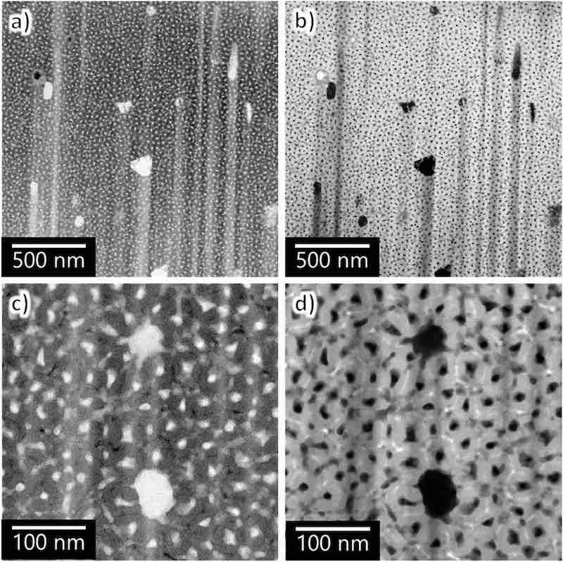
Fig. 9. TEM images of the horizontal cross-section of AA7075–T6 anodized in sulfuric acid (1.5 mol dm−3) for 60 s: (a, c) BF and (b, d) HAADF images. (c, d) High-magnification images.
The elemental maps (Fig. 10) indicate that the cell walls in this porous structure consist of Al and O and contain electrolyte-derived S. At the same time, Zn and Cu are detected at locations where the different contrast spots are observed. To further investigate the composition of the cell walls, EDS was performed on the horizontal section (Fig. 11). The results of the EDS spot analysis at points 1, 2, 3, 4, and 5 indicate the following: (1–3) cell walls are composed of alumina, with the oxide adjacent to the pore containing sulfate ions; (4, 5) elements derived from the fine intermetallic particles (i.e., Al, Zn, and Cu) are detected in the darker area at the cell boundary. Other elements (i.e., Ga and Ti) were introduced because of the contamination derived from the Ga-ion source of the focused ion beam process and the TEM grid.
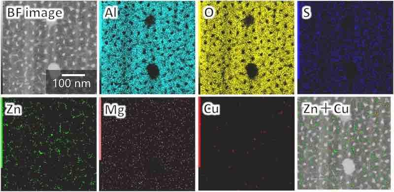
Fig. 10. Elemental maps of the horizontal cross-section of the anodic film formed on AA7075–T6 (the analysis area is the same as in Fig. 9c).
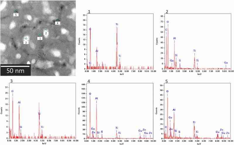
Fig. 11. EDS spectra for the horizontal cross-section of the anodic film formed on AA7075–T6. The anodization conditions were the same as those in Fig. 9. The analysis area differs from the area shown in Fig. 9.
It is well known that Cu concentrates at cell boundaries, particularly triple-point junctions, and forms defects (i.e., voids) during the film growth [18]. The results obtained herein confirm this tendency. At the same time, in contrast to Cu, the distribution and chemical state of Zn in anodic films have been scarcely investigated. A phase with a general composition of Mg–Zn–Al–Cu, which is an isomorphous form of the MgZn2 and MgCuZn stable phases, may form as a nanometer-scale precipitate [15]. To determine the composition and chemical state of the alloying elements in the anodic film, further analyses are required, particularly X-ray photoelectron spectroscopy and electron diffraction.
As mentioned above, the alloying elements were incorporated into the anodic film during its formation. Because the specimen for TEM observation was prepared via short anodization (60 s), the alloying elements could be effectively detected in the anodic film. During prolonged anodization, the anodic film is preferentially dissolved in areas containing alloying elements, resulting in the formation of horizontal pores in the cell walls. In other words, alloying elements incorporated into the anodic film strongly affect the chemical dissolution of the anodic film during subsequent anodization, with the formed pores detrimentally affecting the film properties, i.e., they reduce formation efficiency and film hardness.
Although not the subject of this study, the addition of alcohols, such as ethylene glycol, in the electrolyte increased the formation efficiency and hardness of the anodic film formed on AA7075–T6 [13]. When the ethylene glycol was added to the sulfuric acid, the chemical dissolution of the anodic film as well as the alloying elements incorporated into the film was effectively suppressed during anodization, increasing the coating ratio and the hardness of the anodic film. Thus, the anodization conditions must be optimized for each specific tempering condition according to the industrial application. Although this study was limited to AA7075, further investigation on other aluminum alloy systems will lead to better understanding of the nature of anodization processes and the involved mechanisms.
4. Conclusions
The anodization behavior of AA7075 at a constant current density in sulfuric acid was investigated, focusing on the effect of tempering conditions on the film structure and properties. The voltage–time curves were strongly impacted by the tempering conditions, which was attributed to the effect of tempering conditions on the distribution of aluminum and alloying elements in the substrate. Specifically, a decrease in the film formation efficiency and hardness was observed in anodic films with high porosity and numerous horizontal pores, particularly in AA7075–T6. Thus, although tempering improves the mechanical properties of aluminum alloys, it can detrimentally affect the properties of the anodic film. This study elucidates the effects of aluminum-alloy tempering on anodization behavior, film structure, and film properties, which is expected to contribute to the enhanced utilization of aluminum alloys.
Takuma Sano and Hidetaka Asoh are with the Department of Applied Chemistry, Kogakuin University, 2665–1 Nakano, Hachioji, Tokyo, 192–0015, Japan
- CRediT authorship contribution statement: Takuma Sano: Writing – review & editing, Writing – original draft, Visualization, Validation, Methodology, Investigation, Data curation, Conceptualization. Hidetaka Asoh: Writing – review & editing, Writing – original draft, Validation, Supervision, Methodology, Investigation, Funding acquisition.
- Declaration of generative AI in scientific writing: No generative-AI tools were employed to draft, edit or translate this manuscript.
- Funding: This work was partly financed by the Light Metal Educational Foundation of Japan.
- Declaration of competing interest: The authors declare that they have no known competing financial interests or personal relationships that could have appeared to influence the work reported in this paper.
- Data availability: Data will be made available on request.
References
[1] F. Viana, A.M.P. Pinto, H.M.C. Santos, A.B. Lopes Retrogression and re-ageing of 7075 aluminium alloy: microstructural characterization J. Mater. Proc. Technol., 92 (1999), pp. 54-59, 10.1016/s0924-0136(99)00219-8
[2] J. Buha, R.N. Lumley, A.G. Crosky Secondary ageing in an aluminium alloy 7050 Mater. Sci. Eng. A, 492 (2008), pp. 1-10, 10.1016/j.msea.2008.02.039
[3] K. Ma, H. Wen, T. Hu, T.D. Topping, D. Isheim, D.N. Seidman, E.J. Lavernia, J.M. Schoenung; Mechanical behavior and strengthening mechanisms in ultrafine grain precipitation-strengthened aluminum alloy; Acta Mater., 62 (2014), pp. 141-155, 10.1016/j.actamat.2013.09.042
[4] J.W. Diggle, T.C. Downie, C.W. Goulding; Anodic oxide films on aluminum; Chem. Rev., 69 (1969), pp. 365-405, 10.1021/cr60259a005
[5] W. Lee, S.-J. Park; Porous anodic aluminum oxide: anodization and templated synthesis of functional nanostructures; Chem. Rev., 114 (2014), pp. 7487-7556, 10.1021/cr500002z
[6] H. Masuda, K. Fukuda; Ordered metal nanohole arrays made by a two-step replication of honeycomb structures of anodic alumina; Science, 268 (1995), pp. 1466-1468, 10.1126/science.268.5216.1466
[7] A.R. Clavijo, O.C. Calero, M.M. Gonzalez; Revisiting anodic alumina templates: from fabrication to applications; Nanoscale, 13 (2021), pp. 2227-2265, 10.1039/D0NR07582E; Google Scholar
[8] Y. Zuo, P.-H. Zhao, J.-M. Zhao; The influences of sealing methods on corrosion behavior of anodized aluminum alloys in NaCl solutions; Surf. Coat. Technol., 166 (2003), pp. 237-242, 10.1016/s0257-8972(02)00779-x
[9] R.D. Montoya Z, L.E. Vera, T.Y. Pineda, M.L. Cedeño; Effect of the layer of anodized 7075–T6 aluminium corrosion properties; J. Phys.: Conf. Ser., 786 (2017), Article 012032, 10.1088/1742-6596/786/1/012032; Google Scholar
[10] R. Wang, L. Wang, C. He, M. Lu, L. Sun; Studies on the sealing processes of corrosion resistant coatings formed on 2024 aluminium alloy with tartaric-sulfuric anodizing; Surf. Coat. Technol., 360 (2019), pp. 369-375, 10.1016/j.surfcoat.2018.12.092
[11] M.I. Tawakkal, A.A. Korda; Effect of potential on corrosion behavior of tartaric sulphuric acid anodized 7075 T6 aluminum alloys; J. Phys.: Conf. Ser., 1204 (2019), Article 012038, 10.1088/1742-6596/1204/1/012038
[12] Y. Zhang, Y. Chen, G. Bian, Y. Zhang; Electrochemical behavior and corrosion mechanism of anodized 7B04 aluminum alloy in acid NaCl environments; J. Alloy. Compd., 886 (2021), Article 161231, 10.1016/j.jallcom.2021.161231
[13] T. Sano, Y. Wakabayashi, H. Asoh; Formation of hard anodic films on the 7075-T6 aluminum alloy by anodization in sulfuric acid and ethylene glycol; Surf. Coat. Technol., 459 (2023), Article 129399, 10.1016/j.surfcoat.2023.129399
[14] M. Saenz de Miera, M. Curioni, P. Skeldon, G.E. Thompson; The behaviour of second phase particles during anodizing of aluminium alloys; Corros. Sci., 52 (2010), pp. 2489-2497, 10.1016/j.corsci.2010.03.029
[15] Y. Zhu, K. Sun, G.S. Frankel; Intermetallic phases in aluminum alloys and their roles in localized corrosion; J. Electrochem. Soc., 165 (2018), pp. C807-C820, 10.1149/2.0931811jes
[16] S.J. Garcia-Vergara, K. El Khazmi, P. Skeldon, G.E. Thompson; Influence of copper on the morphology of porous anodic alumina; Corros. Sci., 48 (2006), pp. 2937-2946, 10.1016/j.corsci.2005.10.017
[17] M. Saenz De Miera, M. Curioni, P. Skeldon, G.E. Thompson; Preferential anodic oxidation of second–phase constituents during anodising of AA2024–T3 and AA7075–T6 alloys; Surf. Interface Anal., 42 (2010), pp. 241-246, 10.1002/sia.3191
[18] I.S. Molchan, T.V. Molchan, N.V. Gaponenko, P. Skeldon, G.E. Thompson; Impurity–driven defect generation in porous anodic alumina; Electrochem. Commun., 12 (2010), pp. 693-696, 10.1016/j.elecom.2010.03.008