

Aluminum is a widely used metal found in products worldwide.
 Yehuda BlauIn this article, we will focus on aviation aluminum finishing and summarize the various requirements for the finishing process of this challenging metal.
Top Image: An F-15 outer piston is anodized and sealed with new potassium permanganate sealer at Ogden Air Logistics Complex. AFRL researchers identified and tested this non-chromium sealer as a safer alternative to chromium-based products, and it is now fully incorporated into OO-ALC’s coating process. (U.S. Air Force Photo)
1. Preface
This article focuses on surface preparation before applying the final coating, because the final finish is similar to what various military standards require for coating application.
We will focus on requirements related to cleaning grease, removing oxides, etching, rinsing, chemical testing and analysis, etc.
2. The Process
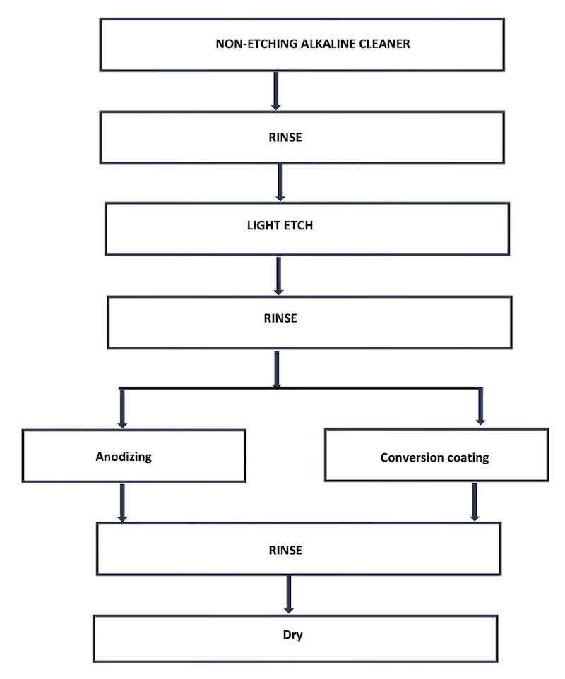 The aluminum finishing process is usually as follows. This process varies, but these are the main stages of finishing to give the metal characteristics that are absent during part production in a metal workshop.
3. Alkaline Cleaner Requirements
3.1 Introduction
Alkaline cleaning is the stage of removing oil and grease from the parts. This stage is important because it can determine coating quality. It mainly consists of builder ingredients like sodium carbonate, polyphosphate salts, and surface-active agents, which are the active ingredients of the cleaner.
Aerospace requirements mostly refer to the non-attacking character of the cleaner solution. Each aerospace company provides a list of approved Alkaline cleaner commercial products that we can use when processing their parts.
Non attacking evaluated by test called coupon test, the coupon test is evaluating the ability of the Alkaline cleaner not to attack the aluminum part during processing.
3.2 The Coupon Test
Coupon test based on weight loss of Aluminum coupon while dipping it in the Alkaline cleaner solution for specified time and measuring the weight loss of the coupon, Stages described in the following table chart.
| Stage | Operation | Outcome /Document |
| 1 | Cut coupon size of 1X2X0.05 inch made of Aluminum 2024 Clad | |
| 2 | Remove oil from the coupon by dipping in the Alkaline solution or by solvent | Clean and not oiled coupon |
| 3 | Weigh the coupon with analytical balance to the nearest 0.1 milligram | Write as Wo parameter |
| 4 | Dip the coupon at the tested Alkaline Cleaner solution for 24±0.5 hours at solution regular working parameters (temperature ; concentration) | Time of beginning and end date ;hour ; minute. |
| 5 | Take out the coupon ; rinse and dry it | Dry coupon ready for weight (Wt.) |
| 6 | Weight the coupon to nearest 0.1 milligram | Write as Weight Parameter |
| 7 | Calculate the difference Wo-Wt. in grams and multiple by 1000 result will be with milligrams | Coupon attack in milligram |
Decoding results: If weight loss is higher than ±10 milligrams, dismiss the cleaner to continue working in the line. One exception is when using the commercial material Turco 4215 NC-LT (Henkel ST) silicone-free material; in this case, it is allowed to lose ±40 milligrams of 2024 clad Aluminum.
Correction action: If the test fails, dump all alkaline cleaner or partially dump it and create a new make-up solution, or replenish the cleaner if partially dumped. In any case, you must repeat the coupon test to qualify the solution for use.
Assess frequency: The coupon test is a part of periodic validation testing, and it must not be later than one calendar month. In case of new make-up or meaningful change in the solution, there is a need to do the test for qualification.
Cause for test failure: In most cases, the reason for failure is penetration of strong alkali, like sodium or potassium hydroxide, into the solution. Sources include racks (where strong alkaline etch solution exists in the line). These Aluminum chips may react with water and produce hydroxide ions, alkaline-neutralized soaps, strong acidic drag-in, and so on.
3.3 Alkaline Solution Make Up Water Quality.
The water makeup of the alkaline cleaner solution will meet the following parameters.
- Conductivity of not more than 25 ppm TDS (total dissolved solids) or 50 micro siemens.
- pH between 5-9
Note: It is advisable to measure the makeup water parameters before adding to the tank to prevent water waste. If, after adding the water to the tank, the conductivity is higher than allowed, dump the solution.
3.4 Intergranular Attack
The intergranular attack procedure is performed per ASTM F945 (or Boeing BSS 7219). The metal used for this procedure is Aluminum 7075-T6511 polished to Ra 32 or less. The part width is 25 mm.
Dip the tested coupon in the Alkaline cleaning solution for at least 30 minutes, then rinse and dry.
Requirements: intergranular attack more than 5 µm (0.0002 in.) or end grain pitting more than 25 µm (0.001 in.) is not acceptable.
Frequency of test: Depends on the aerospace company's standards; some companies require it monthly, others every 3 months, and some require it only when a new makeup solution is prepared or when the solution changes significantly.
3.5 Chemical Solution Analysis
The chemicals in the solution must be controlled to avoid issues with solution strength and effectiveness. Aerospace companies and/or the chemical manufacturing supplier dictate the method for controlling concentration and concentration limits in their technical datasheet.
Frequency of chemical analysis: The frequency depends on the workload on the finishing line and can range from every shift to once a week. The frequency must be such that the established concentration limits are not exceeded.
3.6 Mixing Two Or More Commercial Materials In The Tank's Solution.
It is totally prohibited to add two or more commercial materials to the same alkaline cleaning solution.
4. Deoxidizer
4.1 Introduction
Deoxidizers are chemicals that remove oxides from aluminum metal that interfere with coating formation. Not everyone knows that the aluminum metal has naturally oxide layer that creates after it became aluminum ingot, there is never aluminum pure but always It alloyed and the aluminum number connected to the alloy of it, for example aluminum 2000 is rich with copper, aluminum 7000 is rich with magnesium etc. In most cases, the oxide is a thin molecular layer and not visible, but sometimes oxides form that look like rust; they can be a white powder and sometimes grey, or show black signs from the alloyed ingredients of the metal.
In aerospace, the aim of deoxidizers and desmutting materials is to remove oxides with minimal attack on the aluminum substrate. The main concern in the aviation industry is that, during the deoxidizing stage, the parts may be attacked by the acid. Therefore, this step must be strictly controlled.
4.2 Material Description That Make Up The Deoxidizer Solutions.
Main types of chemicals that make up the deoxidizer are as follows:
- Solution based on Nitric Acid and Iron salts plus fluorides.
- Solution is based on Nitric Acid, Hexavalent chromium, and fluorides.
Solutions based on Iron salts consist of Ferrous iron sulfate salts. This solution was developed to prevent the use of hexavalent chromium and replace it with iron salts. Their main disadvantage is that they can carry over into the coating solution, like a conversion coating solution; in this case, the influence on conversion-coating quality can be dramatic. In other cases, they can enter the sulfuric acid anodizing solution and, by forming iron sulfate salts, disturb the anodizing activity.
Solutions based on hexavalent chromium are the old deoxidizer version, it consists of hexavalent chromium salts together with nitric acid and or sulfuric acid and fluoride salts, there are two main kinds of this material solution, one is the light etching type and the other is the dip etching type which called three acid solution that used mainly in etching cast aluminum that in major case has heavier oxide than the regular processed aluminum.
Fluoride salts role in the solution: The fluoride component in the solution is reacting chemically with the aluminum and sediment it on the bottom of the deoxidizer tank since the aluminum fluoride is poorly soluble in the deoxidizer solution and Aluminum fluoride salt hard-to-dissolve salt formed by a chemical reaction between the aluminum that comes out of the metal and reacts with the fluoride salt, and through this the chemical reaction is created and there is no equilibrium of the reactants in the solution and the amount of aluminum in the solution is only in the equilibrium state of the KSP constant of aluminum fluoride. A shortage of fluoride in the solution will increase the aluminum content and inhibit the deoxidizer's action; this is why we keep the deoxidizer concentration and replenish the solution on time.
Nitric acid role in the solutions: nitric acid does not react with the aluminum and is passive to it. Its key role is to react with the other alloys present on the alloy surface and, in this way, improve the corrosion resistance of the aluminum alloy. If we want good salt spray results per standard requirements, it is advised to increase the nitric acid content in the solution to the maximum allowed concentration set by the manufacturer or the standards; this will improve success in the salt spray corrosion test.
Hexavalent chromium and iron role in the solutions: These components are used to inhibit the deoxidizer solution’s attack on the aluminum parts. The main problem with hexavalent chromium is that it creates health and waste problems. Another problem is using hexavalent chromium before the non-hexavalent chromium conversion coating solution (MIL-C-5541 Type II), which requires several drops of hexavalent chromium to stop the solution from functioning.
4.3 Control Of The Deoxidizer Solution: Etch Rate Test
The most important test for the deoxidizer solution, without doubt, is the etch rate test because it prevents the strong acidic solution from attacking the Aluminum parts, many of which pass Precision Machining with low-tolerance sizes. It is important to keep the test at a controlled temperature, not room temperature. The recommended temperature is 25 degrees Celsius (77 degrees Fahrenheit). This is the correct way to maintain bath temperature; room temperature can drop to 10- 15 degrees Celsius (50–60 degrees Fahrenheit), and the etch-rate results will be incorrect.
The test method and steps are described in the following table:
| Stage | Operation | Outcome /Document |
| 1 | Take one panel or two panels in 100X100X0.05 mm Aluminum 2024 Clad | |
| 2 | Remove oil and grease from the panels by alkaline or solvent cleaning | Clean panels ready for test |
| 3 | Weigh the panel to the nearest 0.1 milligram | Wo |
| 4 | Dip the panel in the Deoxidizer solution for 10-15 minutes | |
| 5 | Take out the panels from the bath ; rinse and dry | |
| 6 | Weigh the panels to the nearest 0.1 milligram | Weight (Wt.) |
| 7 | Calculate the etch rate in microns per minutes per side |
How do you calculate the etch rate? There are several methods to calculate the etch rate. The easiest way to calculate the etch rate is when we know the weight difference: we can calculate the volume of the removed aluminum by dividing it by the specific gravity of the removed part. We know the panel's surface area and volume so that we can determine the height of the removed material. We also divide the etch time by 2 because we removed both sides of the panel.
The formula for calculating the etch rate will be:
𝐸𝑡𝑐ℎ 𝑅𝑎𝑡𝑒(𝜇⁄𝑚𝑖𝑛/𝑠𝑖𝑑𝑒) = [(𝑊𝑜 − 𝑊𝑡)(𝑔𝑟) × 10000(𝑚𝑖𝑐𝑟𝑜𝑛𝑠/𝑐𝑒𝑚)] / [𝑡(min) × A(sq. mm) × ρ(gr/cc)]
When :
- Wo-Wt.: difference in weight in grams; t: dwell time in minutes
- A: surface area of the panel
- ρ: Specific Gravity of the Aluminum (2.78 grams per cubic centimeter)
Calculation example:
- Weight of the panel before etch =27.6780 grams
- Weight of the panel after etch =27.6550 grams
- A = 100 square centimeters (surface area of the panel on one side)
- t=15 minutes
Etch rate calculation = (27.678-27.655)*10000/(100*2*15*2.78) = 0.022 microns per minute per side.
Unit conversion: the result is calculated in SI; when converting to International American units, it is mile/hour/side.
The conversion mathematically is Etch Rate in microns per minute per side × 2.353 miles per hour per side.
Decoding results: Most etch rates across the solution ranges are between 0.042-0.17 microns per minute (0.1-0.4 miles per hour per side). Several solutions have etch rates ranging from 0.063-0.17 (0.15-0.4 miles per hour per side). Heavy etch rate of three acids is 0.34-0.425, and Alkaline etch (which is prohibited in most aerospace standards) is 2.5-3.75 microns per minute per side (5.88-8.82 miles per hour per side).
Replenishment: In case the etch rate is under the low limits of the etch rate its means that no fluorides in the solution, and the replenishment is by adding Hydrofluoric acid or Ammonium bifluoride salt (preferred), Boeing standard made calculation how to increase the etch rate by calculating addition of 0.37 grams per lite ammonium bifluoride will increase the etch rate by 0.1 mile per hour per side (0.042 micron per minute per side), and hydrofluoric acid addition of 0.03% volume percent (0.3 milliliter per liter) will do the same etch rate increasing. If the etch rate is high and over the limit, standards recommend diluting the solution. Another possibility is to add scrap aluminum to the solution, which will reduce the fluoride concentration.
4.4 Other Control Measures
In addition to etch rate control, it is necessary to control the concentration of the components in the solution:
Nitric Acid: acid-base titration will give the exact concentration in the bath. Not all commercial material suppliers list this in their technical data sheets, but it is important for the corrosion resistance of the processed parts.
Deoxidizer concentration: All commercial suppliers include in their technical datasheet the method for determining the content of their commercial material; for iron salt, it is Iodometric titration, and the same applies to hexavalent chromium content.
Fluoride concentration: In the technical datasheet of the manufacturer, it is mostly not written, but there is an analytical method for analysis of fluorides; however, the easiest way to control fluoride, as mentioned above, is by etch rate, which is directly proportional to fluoride concentration.
Aluminum: Several manufacturers mention aluminum content analysis; this is done by acid-base indirect titration to pH=4, then titration to pH=8.5, and subtracting the two.
Temperature: this is an important parameter to control. Many lines do not control temperature because technical datasheets often list room temperature, but this can fluctuate significantly in winter and summer. As mentioned above, solution temperature affects etch rate, and room temperature is 25 degrees Celsius (77 degrees Fahrenheit). This allows etch-rate results to be compared with earlier results and the required etch-rate boundary parameters.
Copper concentration: Copper is the most problematic ion in the deoxidizer solution. Its influence on the corrosion resistance of the aerospace parts is detrimental, and it must be limited in the deoxidizer solution. The maximum allowed copper concentration is 200 ppm. When the solution reaches this concentration value, it must be dumped totally or partially.
Intergranular Corrosion: Intergranular corrosion is a type of corrosion that occurs along the grain boundaries of a metal, rather than uniformly across its surface. The liquid that is in contact with the aluminum part is attacking the grain boundaries, which mostly consist of foreign parts that are not aluminum, and removes it totally or partially. The method of testing it is as follows :
| Stage | Operation | Outcome /Explanation |
| 1 | Cut an extruded section of 7075-T6511 so that the end grain exposed | 7075-6511 alloy 7075 consist of zinc; magnesium; and copper . 6511 means thermal treatment that is vulnerable to intergranular attack |
| 2 | Polish surface to examined to RMS 32 or finer surface finish | RMS 32 surface roughness parameter |
| 3 | Cross section the specimen normal to the surface evaluated and parallel to the grain. | |
| 4 | Perform on the specimen the complete applicable surface preparation process which means alkaline cleaning and rinsing | Surface preparation of the sample before test |
| 5 | Dip the parts in the deoxidizer for 30 minutes to remove at least 25 microns of aluminum rinse the part and dry . | Intergranular solution penetration |
| 5 | Prepare a suitable metallurgical specimen and examine at x500 for intergranular attack and grain end pitting. | Testing and decoding the result |
| 6 | intergranular attack more than 5 µm (0.0002 in.) or end grain pitting in more than µm (0.001 in.) is not acceptable. | Requirement of penetration the grain boundaries of maximum 5 microns attack. and pitting penetration of 25 microns to the aluminum grains as the result of the liquid action on the tested sample |
Intergranular attack attacks the boundaries of aluminum grains and can cause the part to collapse in service if its parameters are higher than needed; it is especially sensitive in the aerospace industry. Testing frequency depends on the standards; some aerospace companies require monthly tests, while others require 3-month tests, and testing is also required when new makeup solutions are introduced and when significant deoxidizer replenishment occurs.
5. Water Quality And Rinses
5.1 Introduction
Water quality is a key feature in the aerospace finishing industry. In most cases, make-up water for solution make-up and rinsing before processing stages is limited in conductivity. The main danger of city water its have chemical ingredients that can be harmful the health operation of processing stage like Chloride that can convert to unwanted Hydrochloric acid (HCL), carbonates that can neutralize acids because of their alkaline character, Calcium that can sequester active components in the processing solution and so on.
5.2 Water Conductivity At Makeup Processing Solutions
Most aerospace companies require makeup water quality before adding makeup chemicals. The maximum conductivity value is 25 ppm of Total dissolved solids (TDS), which is 50 micro siemens units. (TDS X 2 =Micro siemens)
When doing new make-up, first pour half of the tank's volume and take a sample to the lab to check conductivity; if it's higher than 25 ppm TDS, dump the water. Sometimes this happens because the tank isn't cleaned and rinsed enough after dumping the processing solution. Anyway, failing the criteria requires a brief investigation to find the root cause.
Note: pH in the make-up water is not important unless it is extremely high or low (less than 1 or more than 12) because the chemical in the processing will dictate the solution pH.
5.3 Water Quality At Rinsing Before Processing
City or tap water used for rinsing before processing can influence the activity of the processing solution; for example, city water containing chloride, when it enters a strongly acidic deoxidizer and reacts with hydrogen ions to form hydrochloric acid, can significantly affect the etch rate. A similar problem can occur before the coating stages, such as before anodizing: chlorides or nitrates can transfer to the anodizing solution and can interrupt the regular anodizing coating. During conversion coating, chlorides and sulfates from rinsing can carry over and affect the corrosion performance of the parts (and failure of the salt spray 168-hour periodic process validation test per ASTM B117). Several water rinsing steps before the processing stage, per the company's standards, are as follows :
Rinse after Alkaline cleaning and before deoxidizing: 750 ppm TDS maximum. Parts to be dried rinsing conductivity:350 ppm TDS maximum.
Parts rinse before conversion coating: 750 ppm TDS maximum
Parts rinse after deoxidizing and anodizing:150 ppm TDS maximum, with special possibility of 350 ppm TDS in case of conformity to corrosion resistance of the Anodizing coating (resist salt spray test per ASTM B117 within 336 hours)
Note: several standards require a maximum of 50 micro siemens conductivity in the last stage before drying so that minimum salts contaminate the dried parts in service.
5.4 Drying Between Stages
Aerospace requirements absolutely and categorically prohibit parts from drying out during the coating process on any line. The line design must consider the distance between baths so parts do not dry out along the way. The author has seen many lines where this consideration was not taken into account, and parts travel several meters in the transition from bath to bath; there is no way the parts will not dry out along the way, especially in the summer. Rinsing stages play a significant role in preventing parts from drying.
6. Chemical Conversion Coating
6.1 Difference from Mil-Dtl-5541
Mil-Dtl-5551 has been the base standard for chemical conversion coating for several decades. All aerospace standards reference this standard, but several differences exist between aerospace requirements and military standards. The table below describes the main changes made by aerospace companies. Note that not all aerospace companies have the same extra requirements; they vary from company to company.
| Requirement /Test | Mil-Dtl-5541 | Aerospace | More details in section |
| Corrosion Salt spray | 168 hours inclined panel at 6-8% to the vertical | 168 hours inclined panel at 5% to the vertical | |
| Paint Adhesion | Wet test per | Wet test per and other adhesion test depends on aerospace company | 6.1.1 |
| Powder Test | None | Powder test after coating | 6.1.2 |
| Water break test | None | Special water break tests with water and solvents | 6.1.3 |
| Electrical conductivity test | Not obligative ; only per purchasing requirements; 5 panels for the test | Obligative periodic and some companies need as escorting sample 2 panels for the test | 6.1.4 |
6.1.1 Paint Adhesion
The regular test method is the wet test per Federal Standard 141 Method 601.3, and the rating result is per ASTM D3359.
This requirement to prevent paint peeling is the same as in the military test, but other companies require additional adhesion tests; for example, one aerospace company requires an X scribe for the wet test instead of a 1-inch parallel scribe. Another aerospace company asks for a special scribe angle of 30 degrees for cut scribes.
6.1.2 Powder Test
The powder test is done on the finished coated parts to verify that the coating is adhered to the substrate and that there is no smut on the parts. One hour after the parts are coated, white paper is used to wipe the part; if orange or brown powder residue appears, the coating is removable and not adhered. In case the paper is gray or black, it means that there is smut on the part, not because of the coating but more likely that it is from the deoxidizer stage, but it causes failure to the parts.
6.1.3 Water Break Test
A water break test is regularly done after the deoxidizer rinsing stage to ensure the parts are clean. All oil and grease are removed from the parts, but in this case the water break test is done by spraying deionized water on the finished part and checking for drops on the parts.
Another water break test adopted by several aerospace companies is rinsing the opposite side of the sample with MEK and repeating the water break spray test.
6.1.4 Electrical Conductivity
The electrical conductivity test description is the same as in the military standard, but the key difference is that, in the military standard, it is only per the purchasing contract; in aerospace, it is not at the purchaser's discretion.
The test done by several aerospace companies requires each batch to be escorted by a panel that will be tested by the conductivity measuring device; an example of a measuring device is in the following picture (Disclosure: The author of this article markets this device worldwide.)
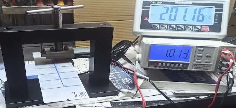
The electrical conductivity test as described in the standards requires 200 Psi pressure. Conductivity is measured over areas of 1 square inch. Resistance of 5000 micro-ohms before the salt spray test and 10000 micro-ohms after a 168-hour salt spray per ASTM B117.
The contact between the measuring device and the panel must have good conductance, and it must be made of copper or silver-coated copper.
7. Anodizing
7.1 Preface
Aerospace anodizing does not differ significantly from regular anodizing, but several differences exist between regular and aerospace requirements.
7.2 Diluted chromate sealing
Boeing developed this sealing, and the solution has the following composition and parameters:
- 70 ppm of Chromic Acid or Sodium Chromate.
- pH between 3.2-3.8 (must be kept tightly)
- Working temperature 195±5-degree Fahrenheit (90.5±2.7 deg Celsius )
The solution must use pure deionized water with a maximum of 12 ppm Total dissolved solids (TDS) and a Silicate content limit of 1 ppm.
No need to rinse the parts after dipping in this sealing solution. From experience, ASTM B117 natural salt spray test gives excellent results with diluted chromate sealing after 336 hours.
7.3 Coating Thickness Sulfuric Acid Anodize
While most of the standards refer to coating weight requirements for the Sulfuric acid anodize, which is impractical as a quality control, several aerospace companies are more practical and require coating thickness between 7.5-12.5 micrometers, which is quite easy and fast to measure. Boeing requirement (class A) is 600 mg/square foot, which is in the rule of thumb 10-12 microns. (1 micron=54.5 mg/sq.ft.).
For colored anodizing, the coating thickness must naturally be higher than for colorless coating; several standards state that, in this case, the coating thickness will be between 15-20 microns.
7.4 Chromic Acid Anodize
Chromic acid anodizing is typically used in aerospace applications because it prevents the fatigue strength reduction seen in other types of anodizing. In aerospace, this characteristic is critical, which is why this anodizing is used (Type I MIL-A-8625). The anodizing solution has chromic acid at 50 grams per liter (5% by weight), and the working temperature is 35±2 degrees Celsius (95±5 degrees Fahrenheit) with a low current density. Coating weight minimum for this process is 200 mg/sq.ft, which is approximately 3.68 micron (0.145 Mil. Inch)
7.5 Boric Sulfuric Anodize
Recently, in the last decade, Boeing has required this anodizing, which is unique for aerospace applications. It has the same characteristics as chromic acid anodizing but omits the need for hexavalent chromium, which is harmful to the environment. Boeing developed this anodizing in its laboratories. This solution is difficult to control and maintain; fungus growth is a problem, and benzoic acid or sodium benzoate must be added (maximum 1000 ppm). Working temperature is convenient at room temperature and current density of 3-6 amp./Sq.ft (0.3-0.6 amp./sq.dec) ,voltage is 15-20 volts . The thickness requirement is similar to chromic acid anodizing.
More information on this unique process is available in BAC 5632.
Yehuda Blau is a chemical engineer who graduated from the Haifa Technion, an Israeli technical institute, and holds a B. A. A degree in Economics and Management from the Open University of Tel Aviv. He began the metal finishing business in 1981 as a chemical lab manager at a company supplying chemicals to the metal finishing market, and from then on he had an extensive career and was quality assurance manager, technical service manager, and product manager of companies that sold chemicals and technology to the metal finishing market for 29 years. For five years of his career, he moved to the client side and was quality assurance and technical manager of plating shops whose main branch specialized in aerospace coating and plating. In the last 12 years he has been independent and owner of YB Plating Engineering and Quality, company that constructs global metal finishing lines (specializing in aerospace lines), consulting plating and metal finishing firms worldwide, selling equipment to the finishing line, and consulting metalworking companies how to be in touch with finishing shops. During his career, he has gained experience in metal finishing in general and aerospace finishing in particular. Visit http://www.ybplating.co.il