


Two spent hard chromium plating solutions were regenerated using an industrially viable electroseparation method to remove metal impurities.
The spent and regenerated baths were used to obtain chromium electrodeposits, which were compared with electrodeposits obtained from freshly prepared, impurity-free plating baths. The morphology of the electrodeposits was characterized by scanning electron microscopy (SEM). Comparative evaluation of hardness and corrosion resistance shows that the physical properties of electrodeposits obtained from regenerated baths are superior to those produced from spent solutions. These properties are close to those obtained for the electrodeposits produced from a freshly prepared hard chromium plating solution.
Because of environmental and economic considerations, various methods are being tried to purify and regenerate heavily used or spent (unusable) hard and decorative chromium plating solutions. Despite the importance of knowing the physical properties of electrodeposits produced from used vs. regenerated solutions, a literature search did not uncover any pertinent information.
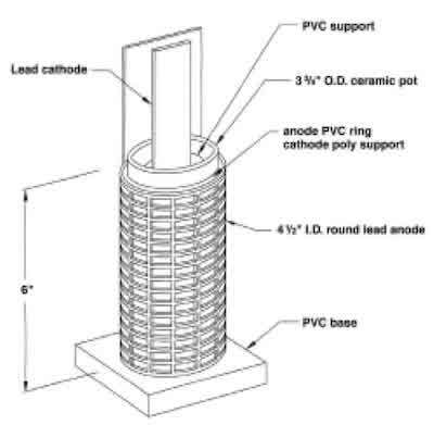 Fig. 1—Experimental round porous pot. Electrode connections not shown. Illustration courtesy of Hard Chrome Plating Consultants, Inc.Electrodialysis and ion exchange are sometimes used to remove metallic impurities from spent chromium plating solutions. However, they are not always practical or economical for small and medium chromium plating installations. The main reasons are that the membranes used are susceptible to mechanical rupture and attack by hot, concentrated chromic acid, and that fairly large amounts of effluent are generated.13 One long-neglected, although promising, practical, simple and economical method involves the application of DC potential via a ceramic membrane to remove metallic contaminants (impurities). This method is also known to practicing electrochemists and electroplaters as the “porous pot” (PP) technique.
Although it was originally used in the electroplating industry in the late 1800s, a lack of clear practical instructions and theoretical explanations suppressed its use for a long time. Recently, this method has gradually gained more acceptance in industry because of its simple design and operation, compactness, and low cost.
 Fig. 2—Industrial-size porous pot.In previous papers,38 we have shown that when a spent, or heavily used or abused, hard chromium plating solution containing metal impurities of iron, nickel, and copper is subjected to a DC potential, the metal cations of Fe+2, Ni+2 and Cu+2 electromigrate through a porous ceramic separator from the anode compartment to the cathode compartment. Because of their inherent negative charge, the dichromate and polychromate anions remain mostly confined to the anode compartment (bulk of the plating solution).9 Trivalent chromium ions simultaneously electromigrate back to the anolyte (bulk of the solution), where they undergo anodic reoxidation and, consequently, hexavalent chromium is regenerated.37 In recent papers,58 we have shown that when hexavalent chromium, in the form of CrO3, dissolved in water or actual plating solution, is used as a catholyte, the pH of the solution remains low and almost unchanged during the metal electromigration process. Evidently, it acts as a buffer. The metal impurities are therefore electrodeposited on the lead cathode and can be conveniently removed from the bulk electroplating solution. An additional advantage is that Cr(VI) anions move across the ceramic membrane from the catholyte back to the plating solution (anolyte); consequently, no hexavalent chromium1,7 is left and is lost inside the “porous pot.” The final benefit is continuous regeneration, by Cr(III) reoxidation on the outside anodes, of deleterious trivalent chromium that is always present in the bulk solution to its hexavalent state.4,10 This important feature (reoxidation) and the influence of anode composition on reoxidation rate are beyond the scope of this paper, although comprehensive research is underway.11
Table 1 Composition of Plating Solutions
| Solution | pH | Impurity | Solution Solution mg/L | % | Regenerated Solution mg/L | % | Removal % |
| Set 1 | 0.4 | Iron | 11680 | 1.17 | 9000 | 0.90 | 23.0 |
| 250 g/L CrO3 | Nickel | 1964 | 0.19 | 1168 | 0.11 | 40.5 | |
| + | Copper | 9408 | 0.94 | 5720 | 0.57 | 39.2 | |
| 2.5 g/L H2SO4 | |||||||
| Set 2 | 0.5 | Iron | 2844 | 0.28 | 2164 | 0.21 | 23.9 |
| 250 g/L CrO3 | Nickel | 544 | 0.05 | 296 | 0.02 | 45.6 | |
| + | Copper | 2356 | 0.23 | 1308 | 0.13 | 44.5 | |
| 2.5 g/L HH2SO4 |
Table 2 Composition of Deposits
| Sample | Iron% | Nickel % | Copper % | Total Impurities % |
| Set 1 | ||||
| a) Deposit from spent solution | 0.48 | 0.12 | 0.23 | 0.83 |
| b) Deposit from regenerated solution | 0.12 | 0.05 | 0.07 | 0.24 |
| Set 2 | ||||
| a) Deposit from spent solution | 0.13 | 0.04 | 0.07 | 0.24 |
| b) Deposit from regenerated solution | 0.10 | 0.04 | 0.07 | 0.21 |
This research investigates and compares the physical characteristics (hardness) and electrochemical properties (corrosion resistance) of electrodeposits produced from new or regenerated versus spent or heavily used hard chromium plating solutions. In addition, we characterized and compared the electrodeposit morphologies by scanning electron microscopy (SEM).
Experimental Procedure
Fig. 1 shows a batch glass reactor, representing a laboratory-size PP used to regenerate spent plating solution. Fig. 2 shows a detailed schematic of an actual industrial-size PP. The outside compartment contains approximately 2000 mL of anolyte (i.e., spent plating solution). The inside compartment, with a capacity of 750 mL, contains a porous ceramic solid membrane (40% porosity and a pore size of approximately 1 µm). Both the anode and cathode are constructed from technical-grade lead grids. The inside compartment contains a solution of 250 g/L of technical-grade chromic acid. The regenerated plating solution was used to electroplate a chromium deposit in a 500mL rectangular plating tank. Sulfuric acid was added to adjust the CrO3/H2SO4 ratio to 100:1. The thermostatically controlled tank contains two square lead plates (25 cm2) as anodes, placed opposite each other. The 6 x 1 cm stainless steel (type 304) cathode, polished to No. 3 finish and thoroughly cleaned, is placed in the center. The temperature of both compartments was kept in all experiments at 45 °C.
Results and Discussion
Evaluation of Deposit Composition
We purified the spent solution using the same procedure and apparatus described in our previous paper.6 The used plating solution labeled “Set 1” was collected from the HBM Electrochemical and Engineering Company, Lansing, IL, and contained 250 g/L of 100:1 Sargent-type bath. The compositionally similar, but artificially contaminated solution labeled “Set 2” was prepared in the laboratory. The purification step involved the application of 14 A direct current (current density of 15.7 A/ft2) at 45 C for a period of 24 hr. Table 1 lists the data on removal of metal impurities.
The results indicated that up to 23 percent iron, 41 percent nickel, and 39 percent copper removal can be obtained from the heavily contaminated spent solution (Set 1). Also, the synthetic spent solution (Set 2) used in this study achieved up to 24 percent iron, 46 percent nickel, and 45 percent copper removal. To obtain a broader set of results, the initial and final impurity content of the Set 1 solution must be greater than the corresponding impurity content of the Set 2 solution.
Because Cr(III) is simultaneously generated inside the PP and regenerated at the outside anodes, measuring changes in Cr(III) concentration is complex and will be addressed in forthcoming papers.
Chromium Deposition
Electrodeposits were plated from 250 g/L CrO3, 100:1, plating solutions listed in Table 1. Plating of both sides was carried out using a constant current (of about 0.280.35 A/ cm2) at 45 C for one hr. The metal cathode used was a 6 x 1 cm 304 SS plate, polished to No. 3 finish. The deposit composition was determined by dissolving the deposits in 1:1 hydrochloric acid and analyzing the solution using inductively coupled plasma spectroscopy (ICP). Table 2 reports the deposit composition. The table shows that the chromium deposits contain mostly chromium, with small amounts of iron, nickel, and copper. Set 2, with a much lower initial impurity concentration, behaved differently, with only the iron concentration affected. The amount of impurities (Ni, Fe, and Cu) in the deposits in Set 1 is proportional to the concentration of impurities in the plating solution, at approximately a 2:1 ratio for Fe and Ni and 4:1 for Cu. After regenerating the contaminated plating solution, the impurity level in the electrodeposits is considerably reduced.
The faradaic efficiency for electrodeposition was determined and is listed in Table 3. The cathode efficiency calculated for deposition from a freshly prepared hard chromium plating bath was 23 percent, close to values reported in the literature for the given current density and temperature. Out of the two spent solutions, the spent Set 1 solution, which contains significantly more impurities than the synthetic spent Set 2 solution, has a lower faradaic efficiency for chromium electrodeposition (Table 3). The data suggest that, within experimental error, the faradaic efficiency for chromium electrodeposition decreases slightly upon purification. This could plausibly be explained by the fact that, in a contaminated solution, in addition to chromium electrodeposition, iron, nickel, and copper electrodeposition can also proceed. The literature confirms that Cr/Fe and Cr/Cu alloys12 and Cr/Ni alloys13 can be plated from a CrO3-based solution. Because the Coulombic charge required to deposit these bivalent impurities is three times lower than that needed for hexavalent chromium, the calculated efficiency is higher for the contaminated solutions than for the regenerated solutions. Another plausible explanation is that Cr(III) complexes portions of Cr(VI), lowering the actual Cr(VI) concentration.14 It is well known that at lower concentrations, chromium baths always plate faster with all the other parameters being equal.
Determination of Mechanical Properties
Hardness measurements characterize the mechanical properties of plated deposits. One major reason for the widespread use of hard chromium plating is its high hardness, which is indirectly related to its excellent wear properties. The Rockwell tester is the commonly used device for measuring hardness. This study used carefully prepared electrodeposits. The data show that the sample prepared from spent Set 1 solution (the most contaminated) has the lowest hardness value of 57.1 Rockwell (scale C).
In contrast, the chromium deposited from a freshly prepared solution has the highest hardness value of 77.5. Hardness was measured by indentation with a 150kg load of Hull Cell panels plated with 25 m of chromium (0.001 in.). Because of the thin chromium layer, the values obtained are comparative rather than absolute (Table 4).
After purifying the spent Set 1 solution and producing the deposit, the deposit hardness was 69.6. This represents a 22 percent increase. The deposit produced from the less contaminated solution (Set 2) had a hardness value of 68.2. After purifying the solution and depositing it, the hardness increased to 77.5, a 14 percent increase. This same value was obtained for the deposit produced from the freshly produced hard chromium plating solution.
Table 3 Faradaic Efficiency for Chromium Electrodeposition
| Solution | Cathode Curr. Efficiency (%) |
| Freshly prepared hard chromium plating solution (control) | 23.0 |
| Set 1 - Spent solution (obtained from industrial bath) | 14.0 |
| Set 1 - Regenerated solution | 13.6 |
| Set 2 - Spent solution (synthetic) | 21.5 |
| Set 2 - Regenerated solution | 19.3 |
Corrosion Measurements
Electrochemical methods are routinely employed to measure the corrosion resistance of metals and alloys. This study used DC potentiodynamic polarization. This method follows the American Society for Testing and Materials (ASTM) procedure D1242. The rate of corrosion of selected chromium coatings was determined in a sodium chloride solution (33 g/L in distilled water). The procedure involved creation of a current (i.e., metal dissolution rate) vs. potential (i.e., oxidizing power) plot. We determined the active-passive regions of chromium corrosion and calculated the net anodic and cathodic currents from the experimental data. The potential at which the anodic and cathodic currents are equal (Ecorr) and the corresponding corrosion current (Icorr) were measured.

Fig. 3—Chromium plate deposited from fresh solution. 1000X. Fig. 4—(a) Chromium plate deposited from (a) spent Set 1 solution; (b) regenerated solution. 1000X.
The Tafel analysis method is used to calculate corrosion characteristics. The corrosion rate in mils per year (MPY) is calculated using Faraday’s law:
Corrosion Rate = dW/dt = MIcorr/nF
where:
- W = weight loss of specimen; M = atomic weight
- n = valence of dissolution t = time
- F = Faraday constant
Table 5 reports the corrosion characteristics of the deposits. The deposit produced from a freshly prepared hard chromium solution showed the lowest metal dissolution rate. The dissolution rate is proportional to the amount of impurities present in the plating solutions. For example, the deposit produced from the spent Set 1 solution with the highest level of metal impurities showed the highest corrosion (i.e., dissolution) rate. Once the contaminated solutions have been regenerated, the electrodeposits produced exhibit greatly lowered metal dissolution rates. These rates are of nearly the same order of magnitude as the corrosion rate observed for the deposit produced from the freshly produced hard chromium plating solution. Since the measured deposits are relatively thin (25 m), those corrosion values should be taken for comparative purposes only.
Morphological Properties
Fig. 3 shows a SEM micrograph of an electrodeposit obtained at 1000X magnification from a freshly prepared hard chromium plating solution, where microcracks typical of chromium electrodeposits are visible. The observed morphology is relatively uniform and appears to form a continuous chromium layer. Figures 4a and 5a are SEM micrographs of the electrodeposits produced from the spent Set 1 and Set 2 solutions. Figures 4b and 5b are SEM micrographs of deposits produced from regenerated Set 1 and Set 2 solutions, respectively. Compared with the SEM micrographs of the hard chromium electrodeposits (Fig. 3), the deposits from the contaminated Set 1 and Set 2 solutions appear to have grain boundaries that are almost in contact, and the deposits seem “burnt.” When the Set 1 and Set 2 solutions were regenerated by electropurification, the micrographs of the obtained deposits appear to display characteristics (Figs. 4b and 5b) that are very similar to those of deposits produced from a freshly prepared hard chromium plating solution (Fig. 3), on the same substrate and under the same plating conditions.
Conclusions
Although experienced chromium platers knew empirically or intuitively that the absence of metallic impurities would improve hardness and corrosion properties, the results presented in this paper clearly quantify the improvement. These results should remind concerned platers that although a chromium plating solution can withstand heavy use and abuse, some important but less apparent properties can be drastically affected.
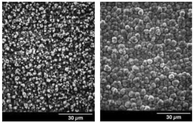
Fig. 5—(a) Chromium plate deposited from (a) spent Set 2 solution; (b) regenerated solution. 1000X.
Acknowledgments: Financial support for this research was provided by the Illinois Waste Management and Research Center, Champaign, IL, and the Materials Technology Center, Carbondale, IL.
References
- R.P. Rentz et al., Proc. AESF SUR/FIN 99, Session V (1999).
- G.C. Cushnie & W. Anderson, 10th AESF/EPA Conf. on Environmental Control, Orlando, FL (1989).
- U.S. Army Corps of Engineers, Evaluation of Electrodialysis for Chromic Acid Recovery and Purification at Corpus Christi Army Depot (ADA242677, Sept. 1991).
- N.V. Mandich, AESF Chromium Colloquium, Orlando, FL (1994).
- J. Pattanayak, N.V. Mandich, K. Mondal, T. Wiltowski & S.B. Lalvani Environ. Technol., 20, 317 (1999).
- J. Pattanayak, K. Mondal, N.V. Mandich, T. Wiltowski & S.B. Lalvani, Metal Fin., accepted for publication.
- S.B. Laivani, J. Pattanayak, K. Mondal, N.V. Mandich & T. Wiltowski, J. Electrochem. Soc., submitted for publication.
- N.V. Mandich, J.R. Selman & C.C. Lee, Plat. and Surf. Fin., 84, 82 (Dec. 1997).
- N.V. Mandich, Plat. and Surf. Fin., 84, 97 (June 1997).
- N.V. Mandich, Metal Fin., 97(6), 100 (1999).
- K. Mondal, N.V. Mandich & S.L. Lalvani, J. Appl. Electrochem., submitted for publication.
- C. Casper, J. Res. Nat’l. Bur. Stand., 14, 643 (1935).
- M.F. Quaely, Plating, 40, 982 (1953).
- N.V. Mandich, Metal Fin., 97(8), 42 (1999).
About the Authors
Dr. N.V. Mandich, CEF, is founder, president, and research director of HBM Electrochemical Co., 2800 Bernice Road, Lansing, IL 60438. He holds a Dipl. in chemical engineering from the University of Belgrade, Yugoslavia; an MSc in theoretical chemistry from Roosevelt University, Chicago; and a PhD in applied electrochemical engineering from Aston University, England. He is a member of the AESF Hard Chromium and Pulse Electrodeposition Plating Committees and an AESF-certified instructor. He is also a Fellow of the Institute of Metal Finishing. He has more than 80 papers published and holds 12 patents. He has received two AESF Silver Medal Awards for Best Paper.
Dr. J. Pattanayak is a research scientist in the Mechanical Engineering & Energy Processes Department at Southern Illinois University, Carbondale. She earned her PhD in solid-state chemistry from the Indian Institute of Technology, India. She has published many journal papers on waste management, electroplating, structural investigation of new compounds, and thin-film fabrication.
K. Mondal is a graduate student in the Mechanical Engineering & Energy Processes Department at Southern Illinois University, Carbondale. He is experienced in chemical, electrochemical, and physical separations, and in modeling these processes.
Dr. S.B. Lalvani holds a PhD in chemical engineering and is a registered professional engineer in Illinois. He is a professor in the Department of Mechanical Engineering & Energy Processes at Southern Illinois University, Carbondale. He has published more than 60 papers on electrodeposition of metals, corrosion, and environmental science.