Electrodeposition of metallic rhenium (Re) is optimized for crack-free coatings through the use of a high-throughput cell to develop pulse-reverse waveforms.
 From top left, Michael McBride, Nathan Brown, Iris Denmark, Amanda Rutledge, Courtney Clark, Jordyn N. Janusz, and Daniel E. Hooks.Pulse waveforms were required for metallic rhenium electrodeposition from water in salt electrolytes. Screening experiments were used to understand how flow rate and the inclusion of citric acid impact the film formation process using a consistent pulse sequence. Flow rate has minimal influence on the observed electrodeposition process, indicating that reaction pathways are more important than diffusion depletion in the chosen electrolyte. The addition of citric acid additionally enabled deposition of metallic Re over the hydrogen evolution reaction.
Drawing parallels to crack-free chromium (Cr) plating, it was postulated that a tailored pulse sequence would provide additional improvements in the electrodeposition process. A 3-factor circumscribed central composite design was utilized to investigate the impact of pulse on time, off time, and peak current control the formation of cracks during electrodeposition. Application of a minimum charge is required to form a metallic Re film, independent of the pulse sequence, consistent with an intermediate conversion process during deposition.
Finally, application of a pulse reverse sequence produced a crack-free, metallic Re coating.
Introduction
Rhenium (Re) coatings could enable many applications in aerospace, catalysis, and other industries. Re has among the highest melting temperature on the periodic table, with excellent corrosion and abrasion resistance, and ductility across a temperature range spanning below zero to its melting point. There is, however, no ambient temperature method to electrodeposit Re that is crack free and scalable to thick coatings on large substrates. Molten salt methods are not easily adaptable to engineering substrates,1 extremely high current density pulsing is not scalable to large substrates,2 and bulk machining or physical deposition methods cannot deliver coatings for all needs. Further, the complexity of Re electrodeposition from room temperature electrolytes is such that successful processes could guide electrolytic processing of many other materials of interest across the periodic table, including vanadium, tungsten, titanium, zirconium, and many other materials of critical need across many applications. The cost and energy savings of new processes for Re electrodeposition and other materials is therefore vast.
Hydrometallurgy and electrodeposition have advanced over hundreds of years, with many significant recent examples. Control of the electrodeposition process through ion transport in solution, charge transfer at the electrode/electrolyte interface, and adatom self-diffusion can be used to tune the crystal structure, texture, and morphology of the deposit.3 Detailed mechanistic studies of these processes have enabled precise control of the morphology, texture, composition, and spatial location of specific constituents for many other materials.4–8 Precise control of the structure of the deposit has been a key contributor to advancements in diverse applications including decorative coatings,9 electrocatalysis,6 energy storage,10 microelectronics,11 and medical devices.12 Though impressive, progress usually relies on much trial and error and therefore remains relatively slow, taking years to decades to develop new processes.
Manipulating the structure of electroplated coatings at the micro- or nano-scale largely relies on expertise and trial-and-error experimentation with a large design space. Electrolyte optimization itself involves decisions on the solvent, composition (metal salt, additives), concentrations, and pH.13 Temperature, degree of agitation, and current profile (pulsed or direct current) must be selected in tandem to target a desired structure and thus function.13 The use of pulsed electrodeposition has been applied to control the nucleation and growth dynamics during electroplating but requires optimization of the pulse height (I or V) and width (ton, toff) but is relatively slow given the many variables to optimize.14,15
Electrochemical high-throughput (HT) approaches have been applied to electrosynthesis of organic compounds,16,17 process-structure screening in conducting polymers,18 electrocatalysis,19 and energy storage systems.20,21 A broad review of the application of HT to electrochemistry has been presented by Wills et al. in 2021.22 While significant advances have been made in applying HT to electrochemical processes, there are few reported platforms focused specifically on rapid exploration of electrodeposition pulse parameters.23,24
Rhenium (Re) electrodeposition from the perrhenate ion presents a challenging demonstration of the utility of HT experimentation applied to electroplating, and representative of many other complex reduction challenges on the periodic table. The perrhenate ion requires the transfer of seven electrons and access to eight protons to be fully reduced to metallic Re. Coupling the electron transfer process with the availability of free protons at the cathode interface multiple times through various intermediate species (oxides, oxyhydroxides) presents a significant challenge. Notably, these intermediate species catalyze the hydrogen evolution reaction (HER), thus promoting the undesirable formation of hydrogen.25 Defects arising from internal stress and/or hydrogen evolution, manifested as prevalent cracking, remain the dominant microstructural feature.
Several mechanisms involving intermediate Re oxide species have been proposed, but these proposed mechanisms have not translated to controllable electrodeposition processes.26–29 With limited understanding of the deposition mechanism, electrochemical process development remains a trial-and-error activity. Controlling proton reactions at the cathode interface is crucial for metallic deposition. Recent work using “water-in-salt” electrolytes has shown that a high concentration of supporting salt can limit the transport of protons to the cathode and suppress hydrogen evolution.30,31 Additional additives can further aid in controlling the availability of free protons by blocking proton absorption on the surface or selectively supplying protons due to pH variations at the cathode interface.32 Despite these advances, coatings remain very thin (<100 nm) and universally cracked. With intended applications relying on fully dense defect-free coatings, thin, cracked, Re is not acceptable.
Here we demonstrate the optimization of pulse-reverse waveform parameters for Re deposition as a model system using a high-throughput approach, yielding thick, crack-free Re coatings. A broad design space is initially explored to understand how pulsed vs direct current electrodeposition and citric acid addition affect the reduction of Re in competition with the hydrogen evolution reaction. The observation that flow parameters did not change outcomes indicated a slow reduction process rather than species diffusion limitation. With these results pointing to possible mechanistic pathways, and reviewing the development of chromium plating, we isolated the need for a waveform containing a reverse pulse to eliminate cracking during the deposition process, yielding high quality crack-free Re coatings.
Experimental
Materials: Electrolytes for Re deposition were comprised of 0.10 M ammonium perrhenate (99.99%, Rhenium Alloys, Inc.), 0.10 M sulfuric acid (ACS Reagent, Fisher Scientific), and 4.70 M lithium chloride (ACS reagent, 99%, Sigma-Aldrich). Citric acid (ACS reagent, 99.5%, Sigma Aldrich) was used as a buffer, with concentration varied between 0.00 M and 0.52 M.
Electrodeposition: Electrodeposition experiments were conducted using a two-electrode setup in a custom-built high-throughput (HT) apparatus. The two-electrode setup was used with consideration for scaling to a practical commercial approach. The cathodes were copper sheets (Kocour Company). Within the HT apparatus, the active area of 50 mm2 was defined by an 8 mm ID rubber O-ring. The anodes in all experiments were graphite rods 1/16 in (1.60 mm) in diameter submerged into the electrolyte 15 mm from the cathode. The cylinders holding the electrolyte were made from quartz glass with a 10 mm OD and 8 mm ID. Experiments were conducted at room temperature using either a pulsed power supply from Dynatronix (DUPR10-3-6 XR) or a VSP-300 6 channel potentiostat from Biologic. Both DC and pulsed modes with varied waveforms were utilized.
In experiments utilizing flow-through, the HT apparatus used a standard syringe pump to deliver the electrolyte at flow rates of 0.025 ml min−1, 0.050 ml min−1, and 0.100 ml min−1 in clear PVC tubing. All experiments utilized pulsed electrodeposition with a peak current of 32 mA (64 mA cm−2), on time of 30 ms, off time of 60 ms and total plating time of 5 hours. Solution volumes were determined to provide fresh electrolyte across the entire plating time.
All static experiments utilized 1.5 ml of electrolyte in the cylinder. Electrodeposition conditions were varied to complete a 3-factor, circumscribed central composite (CCC) design with α = ±1.68. The factors of interest were: (1) applied current density (2) on time, and (3) off time. Two separate CCC designs were conducted; one that applied 25 Coulombs (C) per run and the other that applied 50 C.
The electrolyte was synthesized by adding the sulfuric acid and lithium chloride to water, followed by the addition of ammonium perrhenate. The final volume was then made up by topping up with water. Adding more than 0.1 M ammonium perrhenate resulted in a white precipitate forming. Thus 0.1 M was selected as the concentration. Note that this is substantially larger than the 0.025 M that has been presented in related work in the literature.33
Morphological characterization: Secondary and backscatter images were collected by adhering plated films via double sided copper tape (99.98% purity) to SEM stubs and imaged using a Thermo Fisher Scientific Apreo SEM. All images were collected at a 5 mm working distance with a 2 kV accelerating voltage and a 0.4 nA beam current in OptiPlan mode. No polishing was performed. Striations observed on some micrographs were consistent with the Cu substrates used, which were chosen primarily for ease of preparation and visual contrast with silver or black deposits.
Image analysis: All images were processed similarly using ImageJ and a Python code based upon standard methods for boundary and feature detection formulated to extract crack width and fractional crack area as has been common in optical microscopy for decades.
High-throughput testing apparatus: A custom HT apparatus was designed in this work to rapidly screen the impacts of electrochemical processing parameters on the morphology of electroplated Re. Two different systems based on the same design principles were developed to enable both static and flow experiments as shown in Fig. 1. The design of the HT-apparatus was based upon technologies already present in literature.26 Most HT apparatus in literature use suspended electrodes to screen electrochemical reactions. These designs can be reviewed in work by Gutz et al.,19 Rein et al.,34 and de Campos Rodrigues, et al.35 and focus primarily on electrosynthesis with static electrolytes. Gutz et al. also pioneered a modular electrolysis flow cell where a thin channel for electrolyte separates the two parallel electrodes.36 However, these cells were not intended to perform tailored electrodeposition studies where transport phenomena of liquid and gaseous species can dominate the process. Through redesigned placement of the working and counter electrodes, this work presents two HT electrochemical testing designs which more closely simulate industrial electroplating processes.
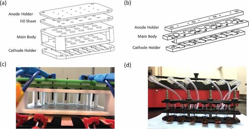
Figure 1. Technical sketch and manufactured HT cells for (a), (c) static electrodeposition cell and (b), (d) flow electrodeposition cell. For scale, the long dimension of the “main body” of the holder is 150 mm, glass tubes are 1.25′ long x 0.375′ diameter.
Static electrodeposition cell design: Figures 1a, 1c depicts the design of the static HT electrodeposition cell. The initial design consisted of 15 cells (5 rows and 3 columns) to run 5 experiments in parallel with 3 repeats. Components were machined out of Garolite 11 (G11) unless specified otherwise. G11 is a glass epoxy laminate with high tensile strength and chemical resistance. The base, designated as cathode holder, provided the electrical connection to the cathode. A 14 mm × 80 mm copper sheet served as a conduction plate for the fifteen 14 mm × 15 mm rectangular cathodes. The main body was machined out of Teflon and used to align the glass vials above the cathodes. It is a non-load bearing component, so chemical resistance was the only required material property. Borosilicate glass vials (OD: 10 mm, ID: 8 mm, H: 30 mm) were used to contain the electrolyte. The fill sheet provided a normal force, sealing the glass vials to the cathode through Square-Profile Oil-Resistant Buna-N O-Rings (ID: 8 mm). Passivated 18–8 stainless steel 12–24 thread screws with corresponding 18–8 stainless steel hex nuts were used to compress these components to form a seal at the top and bottom of the glass cylinders. The fill sheet contained 6 mm holes to allow injection of the electrolyte once the cell is assembled. The volume of the cylinder can hold 1.5 ml of electrolyte. The anode holder houses anode rods and was placed atop the cell once assembled.
In this work graphite rods (OD: 1.6 mm, H: 32 mm) suspended 15 mm above the cathode were utilized to avoid undesirable side reactions at the anode observed in previous work. However, the anode holder can be modified to house both the anode and a reference electrode. The shape, material, and size of the anode as well as the distance from the cathode can be easily varied if an electrical connection can fit through the fill sheet. The design can be scaled and is only limited by number of available channels on a potentiostat or power supply.
Flow electrodeposition cell design: A flow HT electrodeposition apparatus was designed in a row configuration consisting of 6 cells as outlined in Fig. 1. All components were fabricated out of tough PLA using fused deposition modeling with an Ultimaker S5. Tough PLA provides chemical resistance and rigidity for Re electrodeposition and permits rapid remodeling based on experimental needs. The cathode holder design remained unchanged from the static electrodeposition cell. The anode holder was used to secure the anode and seal the glass vial. Borosilicate glass vials were fabricated with horizontal 1.8 mm diameter inlet and outlet ports 6 mm from the top and bottom of the glass vial. The electrolyte flow provided mixing at the cathode surface, as verified by COMSOL models (Fig. S1). The main body was separated into two parts that support and align the vials, wrapping between the flow ports. The flow rate of electrolyte was controlled by syringes ranging from 1 ml–60 ml and dispensed with a 6-channel syringe pump. Connection to the flow electrodeposition cell was obtained through 3 mm internal dimeter PVC tubing.
Results and Discussion
Impact of flow rate and citric acid concentration on electrochemical deposition
Preliminary investigations suggested that the current waveform impacts the electrodeposition process of Re. Figure 2 depicts the benefit of pulsed current deposition compared to DC electrodepostion in terms of resulting morphology. These experiments were conducted in a HT cell with no flow and citric acid for 5 h. A current density of 60 mA cm−2 was used in the DC sample (540 C applied) while the pulse plated sample used a 60 mA cm−2 peak current with ton of 30 ms and toff of 60 ms (270 C). A poorly adhered coating that is primarily black in color was obtained using DC electrodeposition waveforms. Coatings with a metallic silvery color associated with metallic Re was not possible using any DC setting, with and without flow, and with all investaged citric acid concentrations. With pulsed electrodepostion, the main morphological feature observed was cracking associated with internal stress from presumed oxides/hydrides/oxyhydroxides species.37 This paper focuses on process outcomes, and the primary distinguishing feature here is a distinct visual difference between a metallic silver color and a matte black deposit. More detailed evaluation of process intermediates, deposited oxide species, and other characterization is being prepared separately.
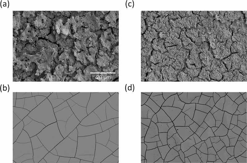
Figure 2. SEM images showing the morphological differences between as-deposited (a) DC and (b) pulse plating with 0.35 M citric acid and (c) DC and (d) pulse plating with 0.52 M citric acid.
It was hypothesized that Re intermediates of oxides/hydrides/oxyhydroxides adsorb to the surface and require only a limited quantity of protons for further reduction to metallic Re.30 Figure 3a displays a simplified Re-H2O Pourbaix diagram for select reactions with assumed activities of Re species of 1. Standard reduction potentials of these known relevant redox couples are summarized in the Supporting Information (Table S1, V vs SHE and SCE). While the activities of the intermediary species are likely less than 1 in the water-in-salt electrolyte, Pourbaix analysis highlights potential thermodynamic pathways, and the challenges associated with Re electrodeposition. Full reduction to metallic Re must occur in a narrow electrochemical window. Further, it can be assumed that steps involving greater than 6 protons and/or electrons are very unlikely to occur kinetically and energetically. Figure 3b highlights the proton and electron requirements for notable Re reduction reaction. The reduction pathway most likely proceeds through ReO2 and ReO3 intermediates. In future work we will further explore these intermediate species through spectroscopy and diffraction, but for the purposes of the current paper, we desired to determine a pathway to Re coating optimization without knowing those details.
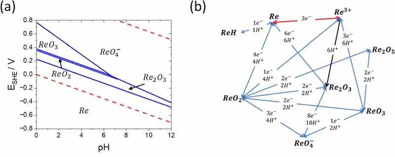
Figure 3. (a) Potential-pH diagram for the Re–H2O system at 298 K, air pressure of 1 bar, and activities of rhenium species at 1. (b). Electrochemical reaction pathways involved in the oxidation of ReO4− in terms of protons and electrons. Blue lines require both protons and electrons, black lines require just protons, and red lines require just electrons.
The data in Fig. 2 suggests that ionic transport effects at the electrolyte-electrode interface are crucial to control to enable deposition of metallic Re. Excess protons at the interface limits both the availability of active sites for the initial reduction of the perrhenate ion (Re+7) and succesive reduction reactions to metallic Re. Pulsed current electrodeposition was used to allow hydrogen atoms time to diffuse from the electrode-electrolyte interface. It may also be possible that pulse times enable selection of specific reduction reactions, but this is not yet known. This hypothesis is consitent with previous Cr deposition that superimposed ripple or pulsed waveforms containing a reverse portion resulted in crack free Cr films.38,39 This transition from cracked to crack-free films in Cr was attributed to driving protons away from the interface during the brief reverse pulse, consistent with Snavely’s proposed reduction mechanisms.33 The reverse pulse was theorized to facilitate reduction from the hydride to metal during each cycle rather than a bulk conversion after some amount of charge had passed, thereby preventing the formation of cracks.
The development of a static and flow electrodeposition HT apparatus enables more detailed analysis on transport effects during the electrodeposition process. Agitation and electrolyte mixing can influence transport phenomena and ion availability at the electrode interface. When multistep chemistry is involved, agitation can be detrimental to current efficiencies as reacting species that need sufficient time in the boundary layer are transported away from the reaction site before secondary reactions can take place.35 Further, the preference for hydrogen evolution over Re electrodeposition limits the concentration of available protons. It is known that citric acid does not form a complex with the perrhenate ion but does significantly improve metallic Re deposition.32,37,40 The addition of citric acid is expected to reduce the expected change in pH, and thus decrease in protons that occur with hydrogen evolution.41
Morphologies obtained from varying citric acid concentration and flow rate with consistent pulse deposition parameters are shown in Fig. 4a. Film cracking is generally observed at all citric acid concentrations and flow rate conditions. All deposits at <0.26 M citric acid showed some signs of mixed oxides, with mostly oxides at 0.0 M static, 0.13 M/0.025 ml min−1, and all oxides at 0.26 M/0.025 ml min−1. Thus, citric acid concentration is demonstrably important for facilitating the conversion from mixed oxides (or other species) to metallic Re. At higher citric acid concentrations (0.39 M and 0.52 M), the Re films generally have consistant morphologies across all flow conditions and are uniformly metallic Re without evidence of mixed oxides. Flow rate appears to have a smaller contribution than citric acid concentration. As shown in Fig. 4b, no clear trend was observed between flow rate and severity of cracking quantified by both fractional crack area and crack width metrics using the 0.52 M citric acid electrolyte. Generally, the current efficiency increased from an average of 3.8% with no flow to 5.4% at a flow rate of 0.05 ml min−1. Further increases to the maximum tested flow rate of 0.10 ml min−1 resulted in a lower current efficiency (3.6%). No clear trend between porosity and crack width with current efficiency was observed. Overall, both the qualitative and quantitative data suggest that the flow rate has minimal influence on the electrodepositon process compared to the citric acid concentration and isolates a set of experimental parameters for focus on pulse/reverse control of crack formation, which we discuss later.
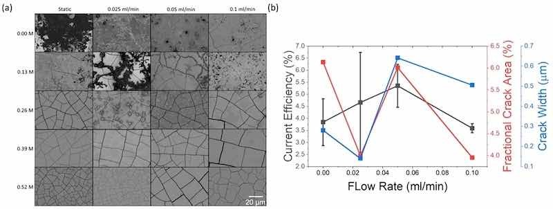
Figure 4. (a) SEM images of as-deposited coatings showing morphological differences between varying citric acid and electrolyte flow (b) current efficiency of 0.52 M citric acid concentration compared to the porosity and crack width in the films. All deposits at <0.26 M citric acid showed some signs of mixed oxides, with mostly oxides at 0.00 M static, 0.13 M/0.025 ml min−1, and all oxides at 0.26 M/0.025 ml min−1. Standard deviation for crack area and width are ∼0.005 and ∼0.2, respectively.
Design of experiment screening of pulse parameters
The morphological results of the flow experiments indicated that static testing with the HT static electrodeposition cell would be sufficient for rapid screening of electrochemical parameters. The major advantage of using the static test setup is the lower volume of electrolyte required and increased number of simultaneous experiments. To investigate the impact of pulse parameters on the quality of Re electrodeposition, a circumscribed central composite (CCC) design with 3 factors without repeats was employed focusing only on forward pulse control (not reverse). The variables studied in this experiment were Ton, Toff, and peak current. Previous development in Cr plating optimizing hard/soft and cracked/crack-free revealed important control parameters that included total coating thickness, temperature, and pulse/pulse-reverse effects. Here we focused only on total thickness as related to total current passed in forward pulse experiments to isolate transition points for subsequent study using reverse pulse as a variable. Experiments to complete the CCC design were conducted with a total charge for each run set at 25 and 50 Coulombs (C). The levels associated with each variable can be seen in Table I. Details of the electroplating pulse settings in the CCC design at both 25 and 50 C are provided in Table II correlated with experiment number. The electrolyte for these experiments consisted of 0.10 M ammonium perrhenate, 0.1 M sulfuric acid, and 0.52 M citric acid.
Table I. List of electrochemical variables and their levels.
| Experimental variable | Low level (−1) | High level (+1) |
| ton (ms) | 30 | 90 |
| ton (ms) | 30 | 90 |
| Peak Current Density (mA cm−2) | 60 | 120 |
Table II. Factor settings for a circumscribed central composite design for Q = 25 and 50 C.
| Exp. No. | TOn (ms) | Toff (ms) | Current density (mA cm−2) | Time Q=25 C | Time Q=50 C |
| 1 | 30 | 30 | 60 | 27.6 | 55.3 |
| 2 | 90 | 30 | 60 | 18.4 | 36.8 |
| 3 | 30 | 90 | 60 | 55.3 | 110.5 |
| 4 | 90 | 90 | 60 | 27.6 | 55.3 |
| 5 | 30 | 30 | 120 | 13.8 | 27.6 |
| 6 | 90 | 30 | 120 | 9.2 | 18.4 |
| 7 | 30 | 90 | 120 | 27.6 | 55.3 |
| 8 | 90 | 90 | 120 | 13.8 | 27.6 |
| 9 | 60 | 60 | 90 | 18.4 | 36.8 |
| 10 | 9.5 | 60 | 90 | 67.1 | 134.2 |
| 11 | 110.5 | 60 | 90 | 14.2 | 28.4 |
| 12 | 60 | 9.5 | 90 | 10.7 | 21.4 |
| 13 | 60 | 110.5 | 90 | 26.2 | 52.3 |
| 14 | 60 | 60 | 39.5 | 41.9 | 83.8 |
| 15 | 60 | 60 | 140.5 | 11.8 | 23.6 |
Figures 5 and 6 display the SEM images from the CCC designs for 25 C and 50 C, respectively. When restricted to 25 C of charge passed only 2 experiments (7 and 14) of the 15 experiments produced metallic Re, both with the typical cracks. Experiment 4 produced a similar morphology but had additional nodular features on top of the cracked surface, which we have noted may coincide with the transition between mixed oxide and metallic Re. Notably, many of the other films at 25 C (1–4, 12, 9, 13, 6, 15—mainly those in the middle portion of the on/off time) show some signs of being near this conversion as at least some cracks that look like the metallic Re films are apparent.
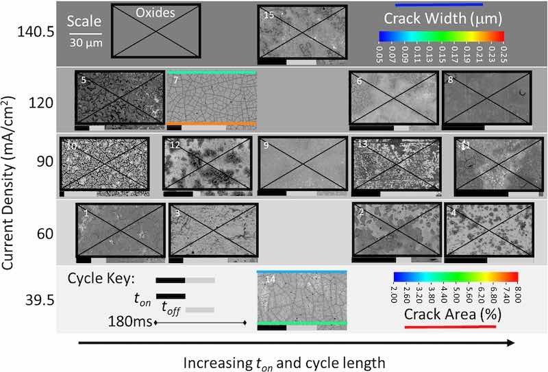
Figure 5. SEM images of all as-deposited coatings for 15 experiments in the CCC design produced with 25 C of passed charge. Increasing on time and cycle length increases from left to right. Where applicable, crack width and fractional area are indicated on the image. Only experiments 7 and 14 produced a metallic Re film, and all others are indicated as mixed oxides with a black box and X.
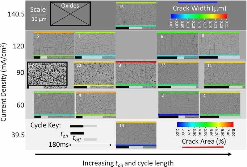
Figure 6. SEM images of all as-deposited coatings for 15 experiments in the CCC design produced with 50 C of passed charge. All but one experiment yielded metallic Re, albeit cracked, demonstrating that total charge was important to facilitate reduction to metal, and providing optimization of the pulse parameters.
It is remarkable, as shown in Fig. 6, that all but one of the experiments (Experiment 10) produced a metallic Re film, considering the only difference between Figs. 5 and 6 is doubling of total charge. The cracked film morphology was observed in 14 of the 15 experiments when the applied charge was increased to 50 C. The exception was at the extreme of the CCC design with a ton = 9.5 ms in Experiment 10 where a non-homogeneous microstructure with large voids between Re domains was observed. Notably, a similar microstructure was produced when the total charge applied was 25 C. It is likely that this short ton is insufficient to allow species within the Nernst diffuse layer to transport to the electrode interface. Many morphologies in this experiment series showed some signs of conversion from oxides but all the other experiments did in fact yield metallic Re. The fact that Experiment 10 was that with the lowest on time for the 50 C series, and that there appeared to be a major transition from 25 C to 50 C both support the hypothesis that the Re deposition process relies on a multistep reduction involving adsorption of mixed oxides and subsequent conversion.
Combined, the results at both levels of applied charge are generally consistent with the literature. It has been proposed that a minimum thickness of ReO2 and/or ReO3 must be deposited/formed before full reduction to metallic Re occurs.27,28,40 The results indicate that with 25 C applied, only a small subset of conditions can achieve this requirement before a homogenous Re film can be produced. The similar morphologies observed at 50 C suggest that multiple reduction pathways can be followed to obtain a given morphology. Further, the selection of electrochemical processing parameters can impact the efficiency in terms of charge required to reach a desired morphology. In future work, additional information about the electrodeposition mechanism may be obtained by measuring the amount of charge required to obtain the homogenous cracked film morphology, or by using methods that more directly probe processes in the double layer.
Ultimately, the utility of a high-throughput screening tool combined with a systematic design of experiment approach is to identify processing variables that optimize the feature of interest. In the case of Re electrodeposition, the ideal morphology is a completely homogenous, metallic film without any void or crack defects.
Pulse-reverse to achieve crack-free coatings
Having resolved this significant optimization to achieve metallic Re with minimized cracks, a reverse pulse was added to the sequence to eliminate cracking from the coating. Leisner and Belov created a map of pulse-reverse conditions as a function of anodic and cathodic charge for pulse-reverse cycles in Cr.38 Based upon their results and the similarities in Cr and Re reduction, a Qanodic/Qcathodic charge reverse ratio of 0.2 may achieve a comparable result in Re. Using the cathodic parameters from experiment 13 (ton = 60 ms, toff = 110.5 ms, Ipeak = 90 mA cm−2), pulse parameters were scaled from pulses in the seconds for Cr to our optimized values of pulses in milliseconds for Re. As shown in Fig. 7, four pulse waveforms were investigated to account for both sequencing of the cathodic, off, and anodic steps with variations in both the time and applied current. All experiments yielded vastly improved, crack-free, Re coatings. The best result was achieved with a high current anodic pulse with short duration immediately following cathodic deposition. Identification of an optimized pulse sequence demonstrates the efficacy of the design of experiments and HT optimization presented here, and delivers the goal of high quality, crack-free Re deposition for thick coatings.
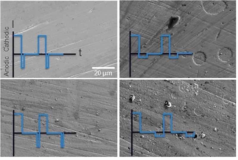
Figure 7. SEM images of as-deposited Re coatings achieved with the indicated pulse-reverse waveforms based upon previous process optimization. All experiments are crack-free, with that shown on the upper left an optimum result. Lines/striations observed are consistent with the substrate before deposition.
Conclusions
A high-throughput (HT) experimental platform was utilized for the optimization of Re pulse electrodeposition. Studies with a flowing electrolyte indicated that citric acid concentration had a larger impact on the reduction of the perrhenate ion to metallic Re than flow rate. A broad design space was subsequently investigated to understand how selection of cathodic pulse parameters impacts the deposition process. Consistent with literature, a minimum charge is required to convert intermediary Re oxides to metallic Re. Changes to the pulse parameters does impact the deposition pathway as observed in the surface morphologies and quantified via crack width and crack area metrics. In general, a longer toff improves the quality of the coating. However, varying cathodic pulses alone does not result in crack free metallic Re coatings.
Applying knowledge from the Cr literature, a crack free metallic Re film was obtained via electrodeposition by applying a Qanodic/Qcathodic charge reverse ratio of 0.2. More specifically, a short duration high current anodic pulse immediately following the cathodic deposition pulse was required to obtain a crack-free metallic Re coating. Obtaining an optimized Re coating in this work demonstrates the utility of design of experiments and HT approaches over trial-and-error experimentation. Future work will focus on scaling for production in several applications, identifying process intermediate species, translation of this success to other systems, and methods to increase optimization rates, including the use of machine learning.
Michael McBride, Nathan Brown, Iris Denmark, Amanda Rutledge, Courtney Clark, Jordyn N. Janusz, and Daniel E. Hooks are with Finishing Manufacturing Science, Los Alamos National Laboratory, Los Alamos, New Mexico.
Acknowledgments: This work was supported by the U.S. Department of Energy through the Los Alamos National Laboratory. Los Alamos National Laboratory is operated by Triad National Security, LLC, for the National Nuclear Security Administration of the U.S. Department of Energy (Contract No. 89233218CNA000001). The authors acknowledge Laboratory Directed Research and Development (LDRD) funding, 20230573ER, at the Los Alamos National Laboratory for funding this work. This research was supported by the Dynamic Materials Properties Campaign (C2) under the direction of the DOE-NNSA. Work was performed, in part, at the Center for Integrated Nanotechnologies, an Office of Science User Facility operated for the U.S. Department of Energy (DOE) Office of Science.
Data Availability: Data will be made available on request.
CRediT Authorship Contribution Statement: Michael McBride: Conceptualization, formal analysis, funding acquisition, investigation, writing—original draft. Nathan Brown: Investigation, Data curation, methodology, writing—original draft. Iris Denmark: Investigation, formal analysis. Amanda Rutledge: Data curation, validation, writing—review and editing. Courtney Clark: Methodology, conceptualization, supervision. Jordyn N. Janusz: Methodology, writing - review and editing. Daniel E. Hooks: Visualization, formal analysis, funding acquisition, writing—original draft, supervision
Declaration of Competing Interest: The authors declare that they have no known competing financial interests or personal relationships that could have appeared to influence the work reported in this paper.
References
- 1. Kuznetsov S. A., Smirnov A. B., Shchetkovsky A. N., Etenko A. L., in Kerridge D. H. and Polyakov E. G. 1998 Rhenium electrochemistry, chemistry and electrodeposition from molten salts Refractory Metals in Molten Salts: Their Chemistry, Electrochemistry and Technology ed D. H. Kerridge (Netherlands: Springer) 273 23
- 2. Puippe J.-C. 1986 Theory and Practice of Pulse Plating (Orlando, FL: American Electroplaters and Surface Finishers Society) 177
- 3. Shen Z., Mao J., Yu G., Zhang W., Mao S., Zhong W., Cheng H., Guo J., Zhang J. and Lu Y. 2023 Electrocrystallization regulation enabled stacked hexagonal platelet growth toward highly reversible zinc anodes Angew. Chem. Int. Ed. 62 e202218452 (accessed 2023/12/15)
- 4. Lee S. A., Yang J. W., Choi S. and Jang H. W. 2021 Nanoscale electrodeposition: Dimension control and 3D conformality Exploration 1 20210012 (accessed 2023/03/16)
- 5. Hu S. et al. 2020 Observing atomic layer electrodeposition on single nanocrystals surface by dark field spectroscopy Nat. Commun. 11 2518
- 6. Shi Y., Huang W.-M., Li J., Zhou Y., Li Z.-Q., Yin Y.-C. and Xia X.-H. 2020 Site-specific electrodeposition enables self-terminating growth of atomically dispersed metal catalysts Nat. Commun. 11 4558
- 7. Tian Y., Liu H., Zhao G. and Tatsuma T. 2006 Shape-controlled electrodeposition of gold nanostructures J. Phys. Chem. B 110 23478
- 8. Sebastián-Pascual P., Jordão Pereira I. and Escudero-Escribano M. 2020 Tailored electrocatalysts by controlled electrochemical deposition and surface nanostructuring Chem. Commun. 56 13261
- 9. Giurlani W., Zangari G., Gambinossi F., Passaponti M., Salvietti E., Di Benedetto F., Caporali S. and Innocenti M. 2018 Electroplating for decorative applications: Recent trends in research and development Coatings 8 260
- 10. Pu J., Shen Z., Zhong C., Zhou Q., Liu J., Zhu J. and Zhang H. 2020 Electrodeposition technologies for Li-Based batteries: New frontiers of energy storage Adv. Mater. 32 1903808 (accessed 2023/12/15)
- 11. Vakanas G. et al. 2015 Formation, processing and characterization of Co–Sn intermetallic compounds for potential integration in 3D interconnects Microelectron. Eng. 140 72
- 12. Figueira G., Rovere C. A. D. and Gargarella P. 2021 Electrodeposition of Fe–Mn alloys from chloride-based bath: A preliminary study for biomedical applications Journal of Materials Research and Technology 13 2527
- 13. Le N. N., Hue Phan T. C., Le A. D., Dung Dang T. M. and Dang M. C. 2015 Optimization of copper electroplating process applied for microfabrication on flexible polyethylene terephthalate substrate Adv. Nat. Sci.: Nanosci. Nanotechnol. 6 035007
- 14. Mohammad Salahi Tohidi P., Safavi M. S., Etminanfar M. and Khalil-Allafi J. 2020 Pulsed electrodeposition of compact, corrosion resistant, and bioactive HAp coatings by application of optimized magnetic field Mater. Chem. Phys. 254 123511
- 15. Richoux V., Diliberto S., Boulanger C. and Lecuire J. M. 2007 Pulsed electrodeposition of bismuth telluride films: Influence of pulse parameters over nucleation and morphology Electrochim. Acta 52 3053
- 16. Siu T., Li W. and Yudin A. K. 2000 Parallel electrosynthesis of α-Alkoxycarbamates, α-Alkoxyamides, and α-Alkoxysulfonamides using the spatially addressable electrolysis platform (SAEP) J. Comb. Chem. 2 545
- 17. Gütz C., Klöckner B. and Waldvogel S. R. 2016 Electrochemical screening for electroorganic synthesis Organic Process Research & Development 20 26
- 18. Briehn C. A., Schiedel M.-S., Bonsen E. M., Schuhmann W. and Bäuerle P. 2001 Single-compound libraries of organic materials: from the combinatorial synthesis of conjugated oligomers to structure–property relationships Angew. Chem. Int. Ed. 40 4680 (accessed 2023/12/15)
- 19. Reddington E., Sapienza A., Gurau B., Viswanathan R., Sarangapani S., Smotkin E. S. and Mallouk T. E. 1998 Combinatorial electrochemistry: a highly parallel, optical screening method for discovery of better electrocatalysts Science 280 1735 (accessed 2023/12/15)
- 20. Matsuda S., Nishioka K. and Nakanishi S. 2019 High-throughput combinatorial screening of multi-component electrolyte additives to improve the performance of Li metal secondary batteries Sci. Rep. 9 6211
- 21. Fleischauer M. D., Hatchard T. D., Rockwell G. P., Topple J. M., Trussler S., Jericho S. K., Jericho M. H. and Dahn J. R. 2003 Design and testing of a 64-Channel combinatorial electrochemical cell J. Electrochem. Soc. 150 A1465
- 22. Wills A. G., Charvet S., Battilocchio C., Scarborough C. C., Wheelhouse K. M. P., Poole D. L., Carson N. and Vantourout J. C. 2021 High-throughput electrochemistry: State of the art, challenges, and perspective Organic Process Research & Development 25 2587
- 23. Rein J., Annand J. R., Wismer M. K., Fu J., Siu J. C., Klapars A., Strotman N. A., Kalyani D., Lehnherr D. and Lin S. 2021 Unlocking the potential of high-throughput experimentation for electrochemistry with a standardized microscale reactor ACS Central Science 7 1347
- 24. de Campos Rodrigues T. and Rosenbaum M. A. 2014 Microbial Electroreduction: Screening for New Cathodic Biocatalysts ChemElectroChem 1 1916 (accessed 2023/07/18)
- 25. Vargas-Uscategui A., Mosquera E., Chornik B. and Cifuentes L. 2015 Electrocatalysis of the hydrogen evolution reaction by rhenium oxides electrodeposited by pulsed-current Electrochim. Acta 178 739
- 26. Kanamura S., Mizuguchi K., Fujita R. and Kondo N. 2014 Electrodeposition of rhenium species at a stainless steel electrode from acidic, neutral, and alkaline solutions J. Electrochem. Soc. 161 D92
- 27. Szabó S. and Bakos I. 2000 Electroreduction of rhenium from sulfuric acid solutions of perrhenic acid J. Electroanal. Chem. 492 103
- 28. Szabó S. and Bakos I. 2004 Electrodeposition of rhenium species onto a gold surface in sulfuric acid media J. Solid State Electrochem. 8 190
- 29. Vargas-Uscategui A., Mosquera E. and Cifuentes L. 2013 Analysis of the electrodeposition process of rhenium and rhenium oxides in alkaline aqueous electrolyte Electrochim. Acta 109 283
- 30. Huang Q. and Lyons T. W. 2018 Electrodeposition of rhenium with suppressed hydrogen evolution from water-in-salt electrolyte Electrochem. Commun. 93 53
- 31. Huang Q. and Hu Y. 2018 Electrodeposition of superconducting rhenium with water-in-salt electrolyte J. Electrochem. Soc. 165 D796
- 32. Sides W. D. and Huang Q. 2020 Ruthenium electrodeposition from water-in-salt electrolytes and the influence of tetrabutylammonium J. Electrochem. Soc. 167 062509
- 33. Snavely C. A. 1947 A theory for the mechanism of chromium plating; a theory for the physical characteristics of chromium plate Transactions of The Electrochemical Society 92 537
- 34. Gütz C., Stenglein A. and Waldvogel S. R. 2017 Highly modular flow cell for electroorganic synthesis Organic Process Research & Development 21 771
- 35. Vazquez-Arenas J. and Pritzker M. 2013 Effect of electrolyte and agitation on the anomalous behavior and morphology of electrodeposited Co–Ni alloys J. Solid State Electrochem. 17 419
- 36. Netherton L. E. and Holt M. L. 1949 Electrodeposition of Rhenium from aqueous solutions J. Electrochem. Soc. 95 324
- 37. Eliaz N. and Gileadi E. 2008 Induced codeposition of alloys of tungsten, molybdenum and rhenium with transition metals Modern Aspects of Electrochemistry ed C. G. Vayenas et al. (Springer New York) 191
- 38. Leisner P. and Belov I. 2009 Influence of process parameters on crack formation in direct current and pulse reversal plated hard chromium Transactions of the IMF 87 90
- 39. Wilson B. A. and Turley D. M. 1989 Development and characteristics of crack-free chromium coatings profuced by electroplating Transactions of the IMF 67 104
- 40. Horányi G. and Bakos I. 1994 Investigation of the electrodeposition and behaviour of Re layers by coupled radiochemical and electrochemical methods J. Electroanal. Chem. 378 143
- 41. Naor A., Eliaz N. and Gileadi E. 2009 Electrodeposition of rhenium–nickel alloys from aqueous solutions Electrochim. Acta 54 6028